Language selection

Search

Patent 2351561 Summary

Third-party information liability

Some of the information on this Web page has been provided by external sources. The Government of Canada is not responsible for the accuracy, reliability or currency of the information supplied by external sources. Users wishing to rely upon this information should consult directly with the source of the information. Content provided by external sources is not subject to official languages, privacy and accessibility requirements.

Claims and Abstract availability

Any discrepancies in the text and image of the Claims and Abstract are due to differing posting times. Text of the Claims and Abstract are posted:

  • At the time the application is open to public inspection;
  • At the time of issue of the patent (grant).
(12) Patent Application: (11) CA 2351561
(54) English Title: IMPROVEMENTS RELATING TO VARIABLE SPEED CONTROL DEVICES
(54) French Title: AMELIORATION DE DISPOSITIFS DE COMMANDE A VITESSE VARIABLE
Status: Deemed Abandoned and Beyond the Period of Reinstatement - Pending Response to Notice of Disregarded Communication
Bibliographic Data
(51) International Patent Classification (IPC):
  • B60L 15/20 (2006.01)
(72) Inventors :
  • LINDSAY, ROBERT WILLIAM (United Kingdom)
  • LEWIS-BOYLE, DAVID (United Kingdom)
(73) Owners :
  • LINTEC INTERNATIONAL LIMITED
(71) Applicants :
  • LINTEC INTERNATIONAL LIMITED (United Kingdom)
(74) Agent: OSLER, HOSKIN & HARCOURT LLP
(74) Associate agent:
(45) Issued:
(86) PCT Filing Date: 1999-11-16
(87) Open to Public Inspection: 2000-05-25
Availability of licence: N/A
Dedicated to the Public: N/A
(25) Language of filing: English

Patent Cooperation Treaty (PCT): Yes
(86) PCT Filing Number: PCT/GB1999/003810
(87) International Publication Number: GB1999003810
(85) National Entry: 2001-05-15

(30) Application Priority Data:
Application No. Country/Territory Date
9825029.3 (United Kingdom) 1998-11-16

Abstracts

English Abstract


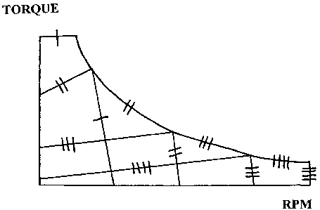
Individual sets of data control points are illustrated on a typical torque
profile of a brushless DC motor showing how the torque capability decreases
with increase of speed of the motor. Each set effectively corresponds to a
particular simulated gear setting for gear changes when driving a vehicle
powered by such an electric motor. The envelope defined by the data control
points for four "gear settings" are indicated by the reference numerals (I,
II, III, IIII). The control equipment for driving the motor can then only
operate within the particular set which is selected (by suitable programming
of an electronic control unit). When the user senses that he has reached
maximum speed under a particular set he can change to a new set and thus
effectively move up a gear. The reverse will of course apply if there is a
desire to decelerate. As the driver arranges to increase the speed of the car
to a maximum he will move up through each of the four gears unitl the maximum
available speed from the motor is achieved.


French Abstract

Sur une courbe type de couple de moteur c.c. sans balais, on porte des groupes séparés de points de commande de données indiquant la décroissance du couple en fonction de la vitesse. Chaque groupe correspond en fait à un point simulé de passage de vitesse lors de la conduite d'un véhicule utilisant un tel moteur électrique. L'enveloppe définie par lesdits points pour quatre rapports est indiquée par les chiffres de référence "I, II, III et IIII"; le dis positif de commande du moteur ne peut alors fonctionner qu'à l'intérieur du groupe donné ayant été sélectionné (par programmation adéquate d'une unité électronique de commande). Lorsque le conducteur perçoit avoir atteint la vitesse maximale dans un rapport donné, il peut sélectionner un nouveau rapport et passer dans une vitesse plus élevée. L'inverse se produit s'il désire décélérer et changer de vitesse. Lorsqu'il désire atteindre la vitesse maximale, il monte successivement les quatre rapports jusqu'à ce que le moteur tourne à son régime maximal.

Claims

Note: Claims are shown in the official language in which they were submitted.


5
CLAIMS
1. A system for creating a variable speed control for
the output drive of a DC electric motor wherein individual
sets of data control points on a torque to RPM speed profile
are predefined and set as operational parameters into
control equipment for driving the motor, such that the motor
can only be driven within the confines of the operational
envelope of any particular set, and switch means is provided
for switching between the separate sets of operational
parameters as desired.
2. A system according to Claim 1, wherein a variable
position acceleration control device is provided which is
able to create a signal related to the position of the
control device to determine the electrical current level
supplied to the motor.
3. A system according to Claim 2, wherein means is
provided to prevent switching between sets of operational
parameters whilst the acceleration control device is
creating an output signal.
4. A system according to any one of Claims 1 to 3,
wherein the sets of data control points are programmed into
an EPROM device.
5. A system according to any one of Claims 1 to 4,
wherein a reversion set of data control points defines
operational parameters for reverse drive of the motor.
6. A system according to Claim 5, wherein control

6
means is provided to prevent operation of the motor under
the operational parameters of said reversion set until the
motor has come to a standstill.
7. A system according to any one of Claims 1 to 6,
wherein a braking device is provided which, when operated,
will send control signals to the motor drive to cause
assisted regenerative braking of the motor.
8. A system according to the combination of Claims 2
and 7, arranged so that the signal sent from the braking
device will override any control signals delivered by said
acceleration control device.
9. A system according to any one of Claims 1 to 8,
including a display panel to indicate the current status of
control devices within the system.
10. A system according to any one of Claims 1 to 9,
including remote-control linkage apparatus connected to
modify the status of the control device within the system
upon receipt of signals from a remote-control operating
device.
11. A system for creating a variable speed control for
the output drive of a DC electric motor substantially as
herein described with reference to the accompanying draw-
ings.
12. Any novel combination of features of a system for
creating a variable speed control for the output drive of a
DC electric motor substantially as herein described and/or
with reference to the accompanying drawings.

Description

Note: Descriptions are shown in the official language in which they were submitted.


CA 02351561 2001-05-15
'WO 00/Z9248 PCT/CB99/03810
1
Improvements relating to Variable Soeed Control Devices
This invention is concerned with means for providing a
variable speed from a DC electric motor. Whilst the
invention is concerned particularly with means for
controlling the speed of a wheeled vehicle it is to be
understood that the device can equally be used for speed and
motion control purposes in relation to wheeled and tracked
vehicles, marine craft, aviation applications and mechanical
handling applications.
According to the present invention there is provided a
system for creating a variable speed control for the output
drive of a DC electric motor wherein individual sets of data
control points on a torque to RPM speed profile are prede-
fined and set as operational parameters into control
equipment for driving the motor, such that the motor can
only be driven within the confines of the operational
envelope of any particular set, and switch means is provided
for switching between the separate sets of operational
parameters as desired.
This system can be used in particular to simulate the
effect of gear changing in a conventional motor vehicle. It
is therefore particularly suited for installation into so
called "go-karts" which are provided for recreational and
competitive track driving. As the user gains speed he can
switch from one set of operational parameters to a new set
and thus simulate the effect of changing from a lower to a
higher gear. It is greatly preferred that the system should

CA 02351561 2001-05-15
WO 00/29248 ~ PC'T/GB99/03810
2
incorporate a variable position acceleration control device
which is able to create a signal related to the position of
the control device to determine the electrical current level
supplied to the motor. This control device can then be used
as a conventional accelerator when the system is incorpor-
ated into a vehicle. Ideally means will be provided to
prevent switching between sets of operational parameters
whilst the acceleration control device is creating an output
signal.
The system can be provided with a reversion set of data
control points which define operational parameters for
reverse drive of the motor. This enables a vehicle, in
which the system is incorporated, to be driven in reverse.
Preferably control means will be provided to prevent
operation of the motor under the operational parameters of
said reversion set until the motor has come to a standstill.
The system may also incorporate a braking device which,
when operated will send control signals to the motor drive
to cause assisted regenerative braking of the motor.
Preferably such a system would be arranged so that (when an
acceleration control device is provided) the signal sent
from the braking device will override any control signals
delivered by said acceleration control device.
In the preferred arrangement the sets of data control
points will be programmed into an EPROM device. The EPROM
device could be replaced by another in which alternative
sets of operational parameters can be defined. This enables
the overall control system to be modified, for example to

CA 02351561 2001-05-15
WO 00/2928 ~ PCT/GB99/03810
3
allow for the different circumstances present in a track
around which a vehicle might be driven. The system can then
be adapted for a variety of tracks, as required.
Ideally the system will include a display panel to
indicate the current status of control devices within the
system. It is also possible to provide a remote-control
linkage apparatus connected to modify the status of the
control device within the system upon receipt of signals
from a remote-control operating device.
A preferred embodiment of the invention will now be
described in more detail with reference to the accompanying
drawing which is a graph illustrating the torque/speed
profile of a DC electric motor.
The drawing illustrates a typical torque profile of a
brushless DC motor illustrating how the torque capability
decreases with increase of speed of the motor. One of the
major objectives of this invention is to provide a means of
simulating gear changes when driving a vehicle powered by
such an electric motor. This is achieved by defining
individual sets of data control points, wherein each set
effectively corresponds to a particular gear setting. The
envelope defined by the data control points for four "gear
settings" are indicated by the reference numerals I, II,
III, IIII. The control equipment for driving the motor can
then only operate within the particular set which is
selected (by suitable programming of an electronic control
unit). When the user senses that he has reached maximum
speed under a particular set he can change to a new set and

CA 02351561 2001-05-15
WO 00/29248 PCT/GB99/03810
4
thus effectively move up a gear. The reverse will or course
apply if there is a desire to decelerate. As the driver
arranges to increase the speed of the car to a maximum he
will move up through each of the four gears until the
maximum available speed from the motor is achieved.
Changing gear from one gear to the next can be achieved
by pressing switches on the steering wheel of the vehicle,
one being provided for upwards changing and the other for
downwards changing. A separate switch will be provided to
enable the system to operate in such a manner that the motor
is reversed (once it has achieved stationary condition),
thus providing a reverse "gear" for the vehicle.
The system can be operated so as to simulate an
automatic gear box. This can be achieved by placing zero
torque blips at specific points such that the drive reduces
no torque for a fraction of a second. This gives the
feeling of a gear change.
It will be appreciated that the system does not need to
be limited to four gear changes as the number can be
increased or decreased as desired.

Representative Drawing
A single figure which represents the drawing illustrating the invention.
Administrative Status

2024-08-01:As part of the Next Generation Patents (NGP) transition, the Canadian Patents Database (CPD) now contains a more detailed Event History, which replicates the Event Log of our new back-office solution.

Please note that "Inactive:" events refers to events no longer in use in our new back-office solution.

For a clearer understanding of the status of the application/patent presented on this page, the site Disclaimer , as well as the definitions for Patent , Event History , Maintenance Fee  and Payment History  should be consulted.

Event History

Description Date
Inactive: Agents merged 2013-10-24
Application Not Reinstated by Deadline 2003-11-17
Time Limit for Reversal Expired 2003-11-17
Deemed Abandoned - Failure to Respond to Maintenance Fee Notice 2002-11-18
Letter Sent 2002-10-07
Inactive: Delete abandonment 2002-10-01
Inactive: Abandoned - No reply to Office letter 2002-08-16
Inactive: Single transfer 2002-08-15
Letter Sent 2002-05-30
Reinstatement Requirements Deemed Compliant for All Abandonment Reasons 2002-05-15
Deemed Abandoned - Failure to Respond to Maintenance Fee Notice 2001-11-16
Inactive: Cover page published 2001-09-19
Inactive: First IPC assigned 2001-08-14
Inactive: Courtesy letter - Evidence 2001-07-31
Inactive: Notice - National entry - No RFE 2001-07-24
Application Received - PCT 2001-07-23
Application Published (Open to Public Inspection) 2000-05-25

Abandonment History

Abandonment Date Reason Reinstatement Date
2002-11-18
2001-11-16

Maintenance Fee

The last payment was received on 2002-05-15

Note : If the full payment has not been received on or before the date indicated, a further fee may be required which may be one of the following

  • the reinstatement fee;
  • the late payment fee; or
  • additional fee to reverse deemed expiry.

Patent fees are adjusted on the 1st of January every year. The amounts above are the current amounts if received by December 31 of the current year.
Please refer to the CIPO Patent Fees web page to see all current fee amounts.

Fee History

Fee Type Anniversary Year Due Date Paid Date
Basic national fee - small 2001-05-15
MF (application, 2nd anniv.) - small 02 2001-11-16 2002-05-15
Reinstatement 2002-05-15
Registration of a document 2002-08-15
Owners on Record

Note: Records showing the ownership history in alphabetical order.

Current Owners on Record
LINTEC INTERNATIONAL LIMITED
Past Owners on Record
DAVID LEWIS-BOYLE
ROBERT WILLIAM LINDSAY
Past Owners that do not appear in the "Owners on Record" listing will appear in other documentation within the application.
Documents

To view selected files, please enter reCAPTCHA code :


To view images, click a link in the Document Description column. To download the documents, select one or more checkboxes in the first column and then click the "Download Selected in PDF format (Zip Archive)" or the "Download Selected as Single PDF" button.

List of published and non-published patent-specific documents on the CPD .

If you have any difficulty accessing content, you can call the Client Service Centre at 1-866-997-1936 or send them an e-mail at CIPO Client Service Centre.


Document
Description 
Date
(yyyy-mm-dd) 
Number of pages   Size of Image (KB) 
Representative drawing 2001-08-26 1 5
Claims 2001-05-14 2 71
Drawings 2001-05-14 1 8
Abstract 2001-05-14 1 55
Description 2001-05-14 4 158
Reminder of maintenance fee due 2001-07-23 1 112
Notice of National Entry 2001-07-23 1 194
Courtesy - Abandonment Letter (Maintenance Fee) 2001-12-16 1 183
Request for evidence or missing transfer 2002-05-15 1 109
Notice of Reinstatement 2002-05-29 1 172
Courtesy - Certificate of registration (related document(s)) 2002-10-06 1 109
Courtesy - Abandonment Letter (Maintenance Fee) 2002-12-15 1 176
Correspondence 2001-07-25 1 24
PCT 2001-05-14 11 394
Fees 2002-05-14 1 48