Language selection

Search

Patent 2352041 Summary

Third-party information liability

Some of the information on this Web page has been provided by external sources. The Government of Canada is not responsible for the accuracy, reliability or currency of the information supplied by external sources. Users wishing to rely upon this information should consult directly with the source of the information. Content provided by external sources is not subject to official languages, privacy and accessibility requirements.

Claims and Abstract availability

Any discrepancies in the text and image of the Claims and Abstract are due to differing posting times. Text of the Claims and Abstract are posted:

  • At the time the application is open to public inspection;
  • At the time of issue of the patent (grant).
(12) Patent: (11) CA 2352041
(54) English Title: TURBINE INLET SCROLL
(54) French Title: VOLUTE D'ENTREE DE TURBINE
Status: Deemed expired
Bibliographic Data
(51) International Patent Classification (IPC):
  • F01D 9/06 (2006.01)
  • F01D 9/02 (2006.01)
  • F01D 9/04 (2006.01)
  • F02C 7/04 (2006.01)
(72) Inventors :
  • SCHUELER, JOSHUA D. (United States of America)
  • ZAGONE, JOHN R. (United States of America)
(73) Owners :
  • ELECTRO-MOTIVE DIESEL, INC. (United States of America)
(71) Applicants :
  • GENERAL MOTORS CORPORATION (United States of America)
(74) Agent: SMART & BIGGAR
(74) Associate agent:
(45) Issued: 2005-09-27
(22) Filed Date: 2001-07-03
(41) Open to Public Inspection: 2003-01-03
Examination requested: 2001-07-03
Availability of licence: N/A
(25) Language of filing: English

Patent Cooperation Treaty (PCT): No

(30) Application Priority Data: None

Abstracts

English Abstract

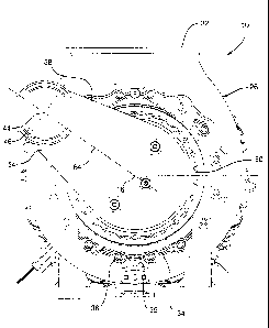
An engine turbocharger includes a turbine inlet scroll for conducting exhaust gas from a laterally offset position to the annular inlet of a turbine wheel. An outer wall defines a generally S-shaped passage connecting an inlet flange with concentric annular outlet flanges aligned on laterally spaced parallel axes. An inner wall positioned near the outlet end of the turbine inlet duct defines an annular passage portion for distribution of exhaust gas to the turbine inlet. Three annularly spaced struts or vanes support the inner wall within the outer wall slightly upstream from the outlet flanges of the scroll. A straight vane is positioned on the central plane of the turbine inlet scroll to support the wall with the least possible interference with gas flow. Second and third vanes are positioned approximately 110 degrees clockwise and counter-clockwise respectively from the first vane and are formed as aerodynamically curved vanes which assist in redirecting the gas flow in an axial direction toward the annular outlet of the scroll to provide relatively even distribution of gas to the turbine inlet.


French Abstract

Un turbocompresseur comprend une volute d'entrée de turbine pour conduire les gaz d'échappement d'une position décalée latéralement vers l'entrée annulaire d'une roue de turbine. Une paroi externe définit un passage généralement de forme en S reliant une bride d'entrée ayant des brides de sortie annulaires concentriques alignées sur des axes parallèles espacés latéralement. Une paroi interne positionnée à proximité de l'extrémité de sortie du conduit d'entrée de la turbine définit une portion de passage annulaire de distribution de gaz d'échappement vers l'entrée de la turbine. Trois jambes ou ailettes espacées annulairement soutiennent la paroi interne à l'intérieur de la paroi externe légèrement en amont à partir des brides de sortie de la volute. Une ailette droite est positionnée sur le plan central de la volute d'entrée de turbine pour supporter la paroi en offrant le moins d'interférence possible à l'écoulement du gaz. La deuxième et la troisième ailettes sont positionnées approximativement à 110 degrés dans le sens horaire et dans le sens antihoraire, respectivement, par rapport à la première ailette et sont formées comme des ailettes courbées de manière aérodynamique qui aident à réorienter l'écoulement du gaz dans une direction axiale vers la sortie annulaire de la volute pour offrir une distribution relativement égale du gaz à l'entrée de la turbine.

Claims

Note: Claims are shown in the official language in which they were submitted.


6

CLAIMS

The embodiments of the invention in which an exclusive
property or privilege is claimed are defined as follows:

1. A turbine inlet scroll for connecting an engine exhaust
manifold outlet with a turbocharger, said inlet scroll comprising:
an outer wall defining a passage leading from an inlet to an
outlet;
outer connecting means at the outlet for connecting the outlet
with such turbocharger;
an inner wall extending from inner connecting means at the
outlet end of the passage into an adjacent portion of the passage and forming
the adjacent portion into an annular passage portion internally defined by the
inner wall, the inner connecting means being spaced within the outer
connecting means;
said outlet aligned on an outlet axis adapted to be
coaxial in assembly with a rotor of such turbocharger, said inlet spaced
laterally away from the outlet and said passage extending from the inlet
toward the axis and formed into said annular passage portion adjacent the
outlet, the annular passage portion curving from largely lateral flow adjacent
an upstream end of the inner wall to essentially axial flow at said outlet;
and
a plurality of struts in the annular passage portion and
connecting the inner and outer walls upstream from the annular outlet, at
least
some of the struts formed as curved vanes for directing gas flow in the
passage toward the axial flow direction adjacent the passage outlet.

2. A turbine inlet scroll as in claim 1 wherein said struts are
aerodynamically shaped vanes to minimize turbulence in gas flow through the
passage.


7

3. A turbine inlet scroll as in claim 2 wherein said struts
include a first strut formed as a straight vane disposed in alignment with gas
flow to the outlet and additional struts spaced angularly away from the first
strut and formed as flow directing curved vanes.

4. A turbine inlet scroll as in claim 3 wherein there are only
three struts, the first strut located adjacent a distal end of the passage and
the
other struts comprising curved vanes spaced angularly on opposite sides of the
outlet.

5. A turbine inlet scroll as in claim 4 wherein said other struts
are spaced about 110 degrees in angularly opposite directions from the first
strut.

6. A turbine inlet scroll as in claim 1 wherein said inlet
includes inlet connecting means aligned on an inlet axis parallel with said
outlet axis.

7. A turbine inlet scroll as in claims 6 wherein said outer wall
defines a generally S-shaped passage.

8. A turbine inlet scroll as in claim. 1 wherein said outer
connecting means includes a flange having fastener openings for attaching the
scroll to such turbocharger.


Description

Note: Descriptions are shown in the official language in which they were submitted.


CA 02352041 2001-07-03
GP-300101
TURBINE INLET SCROLL
TECHNICAL FIELD
This invention relates to engine exhaust driven turbochargers
and more particularly to a turbine inlet scroll and duct for conducting
pressurized exhaust gas from an engine exhaust system to an annular inlet of a
turbine wheel.
BACKGROUND OF THE INVENTION
It is known in the art relating to engine turbochargers to
provide an inlet duct which changes from an open conduit to an annular
passage for delivering pressurized exhaust gas to the inlet of an exhaust
turbine with relatively even pressure and flow distribution around the turbine
annular inlet. In the case of an offset exhaust system connection, the inlet
duct has been joined with an annular scroll that provides a plenum-like volume
to evenly distribute the exhaust gas through angled vanes of an nozzle ring to
the energy converting blades of a turbine wheel. Where a relatively short
axial distance is allowed for connecting an exhaust manifold with a laterally
offset turbine inlet to a free wheeling turbine, the even distribution of
exhaust
gas to an annular turbine inlet from a minimal plenum area requires specific
design of the annular passage portion of the inlet ;>croll.
SUMMARY OF THE INVENTION
The present invention provides a relatively short coupled
turbine inlet scroll and duct wherein an inlet portion connectable with an
engine exhaust manifold is ducted through a generally S-shaped passage to a
laterally offset position where the passage is merged into an annular outlet
connectable with a turbine inlet nozzle ring. An outer wall of the scroll
defines the generally S-shaped passage while an inner wall in the outlet end
of
the passage converts the open passage to an annular passage configuration.


CA 02352041 2001-07-03
2
Struts are provided between the oul:er wall and the inner wall to
support the inner wall within the outlet portion of the inlet scroll. The
shapes
of the outer and inner walls are developed to effecaively diffuse the exhaust
gas leaving the engine exhaust manifold to a larger annular exit area in an
efficient manner. However, the relatively compaca form and tight curves of
the short-coupled inlet scroll cause difficulties in turning the exhaust gas
back
to the axial flow direction and maintaining even distribution of the gas to
the
turbine inlet. These problems are reduced by forming the struts with
aerodynamic shapes that reduce turbulence in the gas flow and by properly
positioning and shaping some of the ducts as flow directing vanes. The vanes
then assist the configurations of the walls in redirecting and evenly
distributing
the exhaust gas across the annular portion of the passage for distribution to
the
connected turbine inlet.
These and other features and advantages of the invention will be
more fully understood from the following description of certain specific
embodiments of the invention taken together with the accompanying drawings.
BRIEF DESCRIPTION OF THE DRAWINGS
In the drawings:
FIG. 1 is a cross-sectional view of an engine turbocharger
having a turbine inlet scroll in accordance with the invention;
FIG. 2 is an exhaust end view of the turbocharger showing the
orientation of the scroll to the turbine section of the turbocharger in one
embodiment of the invention;
FIG. 3 is a turbine end view of a turbine inlet scroll according
to the invention;
FIG. 4 is a cross-sectional view from the line 4-4 of FIG. 3;
and
FIG. 5 is a cross-sectional view of a curved vane from the line
5-5 of FIG. 3.


CA 02352041 2004-08-24
3
DESCRIPTION OF THE PREFERRED EMBODIMENT
Referring now to the drawings in detail, numeral 10 generally
indicates an exhaust driven turbocharger for an engine, such as a diesel
engine
intended for use in railway locomotives or other applications of medium speed
S diesel engines. Turbocharger 10 includes a rotor 12 carried by a rotor
support
14 for rotation on a longitudinal axis 16 and including a turbine wheel 18 and
a compressor wheel 20. The compressor wheel is enclosed by a compressor
housing assembly 22 including components which are supported on an axially
facing first side 24 of the rotor support 14. An exhaust duct 26 has a
compressor end 28 that is mounted on a second side 30 of the rotor support 14
spaced axially from the first side 24.
The exhaust duct 26 is physically positioned between the rotor
support 14 and the turbine wheel 18 to receive exhaust gases passing through
the turbine wheel and carry them to an exhaust outlet 32. A turbine end 34 of
I S the exhaust duct 26 and an associated nozzle retainer assembly 35 are
separately supported by an exhaust duct support 36 that is connected with the
exhaust duct 26 at the turbine end 34. The exhaust duct support 36 also
supports a turbine inlet scroll 38 which receives exhaust gas from the
associated engine and directs it through a nozzle ring 40 to the turbine wheel
18 for transferring energy to drive the turbocharger compressor wheel 20.
In the illustrated exemplary embodiment of the invention, the
turbine inlet scroll 38 (FIGS. 3-5) conducts exhaust gas from an inlet flange
42 centered on an offset axis 44 spaced laterally to one side of and above the
longitudinal axis 16 of the turbocharger rotor. The exhaust gas is conducted
through a relatively short coupled generally S-shaped passage 46 to a scroll-
like outer end forming an annular passage portion 48 that ends at concentric
outer and inner connecting means defined by outer and inner flanges 50, 52.
Fastener openings SS are provided in flange 50 for attaching the scroll to the
exhaust duct support 36 of the associated turbocharger I0. The outer flange
50 is connected with the inlet flange 42 by an outer wall 54 which defines the
generally S-shaped configuration of the passage 46. The inner flange 52


CA 02352041 2001-07-03
4
connects with an inner wall 56 which extends only partially into the passage
46 and is configured to smoothly change the passage from an open duct into
the annular passage portion 48 which extends to the flanges 50, 52.
In order to support the inner wall 56 and inner flange 52 within
the outer wall 54, three struts or vanes 58, 60, 62 are provided spaced
slightly
upstream from the flanges 50, 52 and extending r<tdially between the inner
wall 56 and the outer wall 54. While a minimum number of three vanes is
preferred in order to adequately support the inner wall 56, additional vanes
could be utilized if needed or desired.
A first one of the vanes 58 is optionally located in a centraR
plane 64 evenly dividing the S-shaped passage 46.. The vane is thus aligned
with the flow and is formed as an aerodynamic straight vane which minimizes
turbulence in the gas passing the vane while avoidling deflection of the gas
from its direct path. Vanes 60 and 62 are positioned at locations offset from
the central plane 64 in portions of the annular passage where substantial
turning of the exhaust gas into the annular outlet is required. To assist this
turning in areas where the inner and outer walls are less effective than at
their
upper and lower portions, the vanes 60, 62 are positioned at 110 degree angles
clockwise and counter-clockwise (in FIG. 3) respectively from the centraRly
positioned vane 58. Vanes 60 and 62 are also curved as indicated in FIG. 5 to
assist in redirecting the gas flow adjacent their locations toward the annular
outlet of the turbine inlet scroll and thereby improve even distribution of
gas
to the annular outlet of the scroll and the connected turbine inlet.
The exact angular positioning of the vanes to obtain the desired
even distribution characteristics and the number of vanes required may be
varied as desired and as required by the particular configurations of the
offset
ducts needed for various engine turbocharger app ications. Thus, the
arrangement of the described embodiment, while presently considered optimal
for the particular configuration illustrated, is subject to modification to
meet
the particular conditions of other modified arrangements.


CA 02352041 2001-07-03
While the invention has been descriibed by reference to certain
preferred embodiments, it should be understood that numerous changes cauld
be made within the spirit and scope of the inventive concepts described.
Accordingly, it is intended that the invention not be limited to the disclosed
5 embodiments, but that it have the full scope permitted by the language of
the
following claims.

Representative Drawing
A single figure which represents the drawing illustrating the invention.
Administrative Status

For a clearer understanding of the status of the application/patent presented on this page, the site Disclaimer , as well as the definitions for Patent , Administrative Status , Maintenance Fee  and Payment History  should be consulted.

Administrative Status

Title Date
Forecasted Issue Date 2005-09-27
(22) Filed 2001-07-03
Examination Requested 2001-07-03
(41) Open to Public Inspection 2003-01-03
(45) Issued 2005-09-27
Deemed Expired 2015-07-03

Abandonment History

There is no abandonment history.

Payment History

Fee Type Anniversary Year Due Date Amount Paid Paid Date
Request for Examination $400.00 2001-07-03
Registration of a document - section 124 $100.00 2001-07-03
Application Fee $300.00 2001-07-03
Maintenance Fee - Application - New Act 2 2003-07-03 $100.00 2003-06-19
Maintenance Fee - Application - New Act 3 2004-07-05 $100.00 2004-06-18
Final Fee $300.00 2005-05-03
Registration of a document - section 124 $100.00 2005-06-01
Maintenance Fee - Application - New Act 4 2005-07-04 $100.00 2005-07-04
Maintenance Fee - Patent - New Act 5 2006-07-04 $200.00 2006-06-19
Maintenance Fee - Patent - New Act 6 2007-07-03 $200.00 2007-06-18
Maintenance Fee - Patent - New Act 7 2008-07-03 $200.00 2008-06-18
Maintenance Fee - Patent - New Act 8 2009-07-03 $200.00 2009-06-17
Maintenance Fee - Patent - New Act 9 2010-07-05 $200.00 2010-06-17
Maintenance Fee - Patent - New Act 10 2011-07-04 $250.00 2011-06-22
Maintenance Fee - Patent - New Act 11 2012-07-03 $250.00 2012-06-19
Maintenance Fee - Patent - New Act 12 2013-07-03 $250.00 2013-06-20
Owners on Record

Note: Records showing the ownership history in alphabetical order.

Current Owners on Record
ELECTRO-MOTIVE DIESEL, INC.
Past Owners on Record
GENERAL MOTORS CORPORATION
SCHUELER, JOSHUA D.
ZAGONE, JOHN R.
Past Owners that do not appear in the "Owners on Record" listing will appear in other documentation within the application.
Documents

To view selected files, please enter reCAPTCHA code :


To view images, click a link in the Document Description column. To download the documents, select one or more checkboxes in the first column and then click the "Download Selected in PDF format (Zip Archive)" or the "Download Selected as Single PDF" button.

List of published and non-published patent-specific documents on the CPD .

If you have any difficulty accessing content, you can call the Client Service Centre at 1-866-997-1936 or send them an e-mail at CIPO Client Service Centre.


Document
Description 
Date
(yyyy-mm-dd) 
Number of pages   Size of Image (KB) 
Representative Drawing 2002-03-06 1 20
Cover Page 2002-12-13 2 59
Abstract 2001-07-03 1 30
Claims 2001-07-03 2 67
Description 2001-07-03 5 209
Drawings 2001-07-03 3 131
Description 2004-08-24 5 209
Claims 2004-08-24 2 67
Representative Drawing 2005-09-08 1 20
Cover Page 2005-09-08 1 53
Assignment 2001-07-03 6 271
Fees 2003-06-19 1 29
Prosecution-Amendment 2004-04-01 2 66
Fees 2004-06-18 1 33
Prosecution-Amendment 2004-08-24 4 177
Correspondence 2005-05-03 1 32
Assignment 2005-06-01 15 1,125
Fees 2005-07-04 1 28
Correspondence 2011-09-13 3 116
Correspondence 2011-09-23 1 14
Correspondence 2011-09-23 1 16