Note: Descriptions are shown in the official language in which they were submitted.
CA 02352057 2001-05-28
WO 01/25140 PCTICA00/01145
FUEL CELL POWER GENERATION
SYSTEM WITH AUTOTHERMAL REFORMER
Field of the Invention
The present invention relates to electrochemical fuel cell electric
power generation systems. Mare particularly, the present invention relates
to an integrated fuel cell power plant suitable for use in stationary and
vehicular applications, especially for use in submarines.
Background of the Invention
The search for alternative power sources has focused attention on
IS the use of electrochemical fuel cells to generate electrical power. Unlike
conventional fossil fuel power sources, fuel cells axe capable of generating
electrical power from a fuel stream and an oxidant stream without
producing substantial amounts of undesirable by-products, such as sulfur
oxides, nitrogen oxides and carbon monoxide. However, the commercial
viability of fuel cell electric power generation systems will benefit from the
ability to eff ciently and cleanly convert conventional hydrocarbon fuel
sources, such as, for example, gasoline, diesel, natural gas, ethane, butane,
light distillates, dimethyl ether, methanol, ethanol, propane, naphtha,
kerosene, and combinations thereof, to a hydrogen-rich gas stream with
increased reliability and decreased cost. The conversion of such fuel
sources to a hydrogen-rich gas stream is also important for other industrial
processes, as well.
Fuel cell electric power generation systems are of particular
significance in the submarine industry, as they offer significant advantages
relative to conventional diesel-electric and nuclear power plants often used
in submarines. Fuel cell electric power generation systems offer high
energy conversion eff ciency and operate quietly, thereby linuting the
opportunity for detection of the acoustic signature of the vessel. Air-
independent submarine propulsion systems, with on-board storage of fuel
and oxidant, avoid the need for snorting periods (drawing air from above
the ocean surface) during a mission, reducing the optical and radar
SUBSTITUTE SHEET (RULE26)
CA 02352057 2001-05-28
WO 01/25140 - 2 - . PCTICA00I01145
signature of the vessel. The fuel cell propulsion system requires less on-
board oxygen and fuel storage for a given mission than other air-
independent propulsion systems because of the high efficiency of the fuel
cell as an energy conversion device: Fue! cell powered submarines
5 therefore offer the advantage of long submerged mission durations. Also,
relative to nuclear power plants; fuel cell electric power generation systems
have fewer human health and safety concerns, particularly as to fuel
storage and handling.
In submarine applications, one or more fuel cell stacks may be
connected in series, or, more commonly, in parallel with a conventional
battery bank. Individual fuel cells and stacks are electrically connected to
meet the desired voltage and current requirements of the system. The fuel
cells may be used as the primary source of power for submarine propulsion
and for other loads on board, and for charging the batteries. The batteries
15 may be used to augment the fuel cell stack power output when power in
excess of the maximum fuel cell output is required.
In fuel cell power generation systems, such as those used to power
submarines, the fuel cell stack may be supplied with an oxidant stream
composed of substantially pure oxygen or oxygen in an inert carrier gas
20 such as nitrogen or argon, for example. The oxygen may be stored on-
board the submarine as liquid oxygen ("LOX"), or may be generated on-
board by decomposition of an oxygen source such as hydrogen peroxide.
In some instances, the fuel cell power generation system may be adapted to
use air as the oxidant stream during surface operations, thereby reserving
25 the stored oxygen supply for operation during submersion.
The fuel stream is such systems is often substantially pure hydrogen
obtained by purification of a hydrogen-containing reformate stream
generated by the on-board catalytic steam reformation of a process fuel
stream such as methanol, kerosene, diesel and other alcohols or
30 hydrocarbon-based fuels. In other systems, hydrogen storage devices, such
as metal hydrides or high pressure gas cylinders are used to store hydrogen
fuel on-board, as well as or instead of an on-board reformer.
SUBSTITUTE SHEET (RULE26)
CA 02352057 2001-05-28
WO 01!25140 PCT/CAOOI01145
-3-
To be effectively employed in submarine applications, fuel
processing components such as vaporizers, reformers and hydrogen
separators should be compact, robust and reliable. Examples of radial flow
fuel vaporizer and reformer designs are disclosed in U.S. Patent No.
5 5,676,911, which is incorporated herein by reference in its entirety.
Diffusion membrane hydrogen separators, such as palladium or
palladium membrane separators, are particularly suitable for use in
reformate stream purif cation on a submarine since they are compact and
their operation is not affected by the motion of the vessel. They generally
10 separate the reformate stream into a high-purity hydrogen stream and a
raffmate stream, which is depleted in hydrogen and contains other
reformate stream components, primarily carbon dioxide. The substantially ,
pure hydrogen stream is then delivered to the fuel cell stack as the fuel
stream.
15 A conventional palladium alloy-based hydrogen separation device
includes an arrangement of thin-walled palladium alloy tubular members
sealed in a shell (similar to a conventional shell-and-tube heat exchanger).
Alternative approaches to metal diffusion membrane separator designs may
also be used. These include composite noble metal tubes, thin filin metal
20 deposition on porous substrates, or supported rolled film designs. In these
designs the metal or metal alloy film thickness is drastically reduced
compared to conventional palladium alloy tubes, reducing the cost of the
unit for a given capacity of gas separation. Structural strength in these
designs is provided by a less expensive hydrogen permeable support
25 material, while thin, supported metal or metal alloy film provides hydrogen
selectivity. Examples of such designs are described in Edlund et al. U.S.
Patent No. 5,645,626, and related patents; and in Buxbaum U.5. Patent .
Nos. 5,108,724 and 5,215,729.
In selecting preferred operating pressures far the fuel cells and for
30 the reactant supply and processing systems, factors such as the need to be
able to discharge waste exhaust streams overboard at diving depth should
be considered. One approach is to operate the entire fuel cell power
SUBSTITUTE S~iEET (RULE26)
CA 02352057 2001-05-28
WO 01/25140 PCTlCA00/01145
-4-
generating system, including the fuel processing system and fuel cells, at a
pressure higher than the typical maximum depth pressure so that waste
exhaust streams may be discharged without the need for further pumping.
This is the preferred option when the fuel cell is operating on a dilute or
5 impure fuel stream, and there is not a closed fuel loop for recirculating
the
fuel stream through the fuel cell stack. In this case the fuel stream exiting
the stack should be vented or discharged from the stack, and ultimately
from the vessel, so preferably it is at high pressure.
If subsystems generating waste exhaust streams are operating at
10 lower pressures than depth pressure, the exhaust gases should be
compressed prior to discharge to the ocean, be it directly or via a scrubber.
Compressing exhaust streams for discharge overboard represents a
significant parasitic power load and requires the use, storage and
maintenance of additional equipment. Conversely, discharging exhaust
I5 gases via a scrubber at low pressures requires significantly increases the
space needed for the system, as low-pressure scrubber equipment is
signif cantly larger than high-pressure equipment. This is also less than
desirable, as space is generally at a premium on-board.
A fuel cell power generation system suitable for use in submarine
20 applications is described in commonly assigned U.S. Patent No. 6,063,515,
incorporated herein by reference in its entirety. The fuel cell power
generation system described therein employs a catalytic burner to heat a
heat transfer fluid, which in turn is used to heat a vaporizer and steam
reformer. A hydrogen separator is used to obtain a substantially pure
25 hydrogen fuel stream from the reformats stream, which is directed to and
recirculated through the fuel cell stack in a closed loop. The fuel
processing subsystem is operated at high pressure, which facilitates the
discharge of waste streams overboard, and the fuel cell stack is operated at
a substantially lower pressure. The preferred fuel for the fuel processing
30 system is disclosed as a methanol-water mixture.
The use of methanol or a methanol-water mixture as a fuel for fuel
processing systems for use in a submarine may be less than desirable in
CA 02352057 2001-05-28
WO OI/2514~ PCTICA00/01I45
-5-
some applications. Currently, methanol is not a readily available fuel, and
the lack of availability may significantly limit the ports at which it may be
possible to refuel. For convenience and availability diesel, such as DF-2
{No. 2 diesel), for example, would be a preferable fuel. Such fuels also
have a higher energy density relative to methanol, and so would also be
preferable in that a smaller volume of fuel for a given mission range would
need to be stored on-board.
Diesel, however, is notoriously difficult to reform in a steam
reformer. Further, the high levels of sulfur in diesel fuel typically requires
sulfur removal components, such as a hydrodesulfurizer (HDS) and
hydrogen sulfide scrubber, for example, to be located upstream of the
steam reformer in order to avoid poisoning of the steam reformer catalyst.
This adds complexity and cost to the fuel processing subsystem, and takes
up additional valuable space within the vessel. Thus, employing a steam
reformer to reform diesel may be less than desirable.
As mentioned above, the fuel processing subsystem of the fuel cell
power generation system disclosed in U.S. Patent No. 6,063,515, operates
at high pressure, thereby facilitating the discharge of waste exhaust streams
overboard. The catalytic burner outlet stream is directed to a carbon
dioxide dissolves, where it is dissolved in sea water at divixig depth
pressures and discharged overboard. The catalytic burner outlet stream
may also contain a significant amount of oxygen, however, which is lost on
discharge. In air-independent propulsion systems, submerged mission
duration is typically limited by the amount of oxidant stored on-board.
Therefore, it would be desirable to recover the oxygen lost on discharge of
the waste exhaust stream.
Accordingly, it would be desirable to have a fuel cell electric power
generation system for use in submarine applications, for example, that
could easily and efficiently operate using diesel as a fuel, and could make
more efficient use of the oxygen stored on-board when used as an air-
independent propulsion system.
CA 02352057 2001-05-28
WO 01125140 PCT/CA00/01145
-6-
Summary of the Invention
Methods and apparatus relating to the present fuel cell electric
power generation system are provided.
In one embodiment, which is particularly suited for use in
5 submarine applications, the present fuel cell electric power generation
system comprises:
(a) a fuel processing subsystem for converting a fuel stream to a
reformats stream comprising hydrogen, the fuel processing
subsystem comprising an autothermal reformer;
(b) a hydrogen separator located downstream of the fuel
processing subsystem and fluidly connected thereto for
receiving the reformats stream, the separator comprising a
membrane for separating the reformats stream into a
hydrogen-rich stream and a raffinate stream;
(c) a full cell stack comprising at least one fuel cell fluidly
connected to receive an oxidant stream, and the hydrogen-
rich stream from the hydrogen separator;
(d) a burner fluidly connected to receive the raffinate stream and
to combust the raffmate stream therein to produce a burner
outlet stream comprising carbon dioxide and oxygen; and
(e) a carbon dioxide scrubber fluidly connected to receive the
burner outlet stream for removing at least a portion of the
carbon dioxide from the burner outlet stream and for
recovering at least a portion of the oxygen from the burner
outlet stream and supplying an oxygen-containing stream to
the burner.
The fuel processing subsystem of the present system may further
comprise a hydrogen sulfide scrubber located downstream of the
autothermal reformer and fluidly cannected thereto for receiving the
reformats stream. The hydrogen sulfide scrubber may comprise a metal
oxide absorbent bed or a hot carbonate scrubber, for example. Preferably,
the hydrogen sulfide scrubber comprises a zinc oxide absorbent bed.
CA 02352057 2001-05-28
WO 01/25140 PCTICA00/01145
_7_
The fuel processing subsystem of the present system may also
further comprise a shift reactor located downstream of the hydrogen sulfide
scrubber and fluidly connected thereto to receive the reformate stream
therefrom.
S In the present system, the hydrogen separator may consist of plate-
and-frame, spiral wound, or hollow fiber modules, for example.
Preferably, the hydrogen separator can tolerate transmembrane pressure
differentials of at least 2750 kPa. More preferably, the hydrogen separator
can tolerate transmembrane pressure differentials of at least 3450 kPa.
The membrane of the hydrogen separator may comprise one or
more of: palladium membranes; palladium alloy membranes; platinum
membranes; platinum alloy membranes; titanium alloy membranes; ceramic
membranes; zeolite molecular sieve membranes; carbon molecular sieve
membranes; inorganic poly-acid membranes; and composite membranes
1S thereof. Preferably, the membrane comprises a palladium membrane or
palladium alloy membrane; more preferably, the membrane is supported.
In the present system, the fuel cell stack may comprise at least one
solid polymer electrolyte fuel cell. The fuel cell stack may also comprise
an array of fuel cell stacks, preferably an array of solid polymer electrolyte
fuel cell stacks.
The burner of the present system may comprise a catalytic burner.
The present system may further comprise a fuel supply for
supplying the fuel to the fuel processing subsystem. The fuel may consist
of diesel, gasoline or liquid synthetic hydrocarbon fuels, for example.
2S Preferably, the fuel comprises diesel fuel, such as No. 2 diesel fuel, for
example.
The present system may also further comprise an oxidant supply for
supplying oxidant to the fuel processing subsystem. The oxidant supply
may comprise liquid oxygen, hydrogen peroxide or air, for example.
30 Where the oxidant supply comprises hydrogen peroxide, the fuel processing
subsystem further comprises a decomposer for converting the hydrogen
peroxide to substantially pure oxygen.
CA 02352057 2001-05-28
WO 01/25140 PCT/CA00/01145
_g_
The present system may further comprise a water supply for
supplying water to the fuel processing subsystem.
The present system may also further comprise a compressor fluidly
connected to the carbon dioxide scrubber for pressurizing the oxygen-
containing stream supplied to the burner.
Another embodiment of the present fuel cell electric power
generation system comprises:
(a) a fuel processing subsystem for converting a fuel stream to a
reformate stream comprising hydrogen, the fuel processing
subsystem comprising an autothermal reformer;
(b) a hydrogen separator located downstream of the fuel
processing subsystem and fluidly connected thereto for
receiving the reformate stream, the separator comprising a
membrane for separating the reformate stream into a
hydrogen-rich stream and a raffinate stream;
(c) a turbo-compressor mechanically connected to a turbo-
expander, the turbo-compressor for compressing air to
produce a compressed air stream;
(d) a fuel cell stack comprising at least one fuel cell fluidly
connected to receive the hydrogen-rich stream from the
hydrogen separator, and the compressed air stream from the
turbo-compressor, and producing an anode exhaust stream, a
cathode exhaust stream, and electric power therefrom; and
(e) a burner fluidly connected to receive the raffinate
stream and to combust the raffinate stream therein to
produce a burner outlet stream,
wherein the turbo-expander is fluidly connected to receive the
burner outlet stream from the burner.
The burner may also be fluidly connected to receive the cathode
exhaust stream from the fuel cell stack.
A method of operating the present fuel cell electric power
generation system in a submarine comprises:
CA 02352057 2001-05-28
WO 01/25140 PCTICA00/01145
-9-
(a) catalytically reforming a fuel stream in an autothertnal
reformer to produce a reforrnate stream comprising
hydrogen;
(b) separating the reformate stream into a substantially pure
hydrogen stream and a raffinate stream in a hydrogen
separator comprising a hydrogen separation membrane;
(c) supplying the hydrogen stream and an oxidant stream from
an oxidant supply to the fuel cell stack, producing an anode
exhaust stream from the hydrogen stream, a cathode exhaust
stream from the oxidant stream, and electrical power;
(d} combusting the raffinate stream in a burner to produce heat
and a burner outlet stream comprising carbon dioxide and
oxygen;
(e) supplying the burner outlet stream to a carbon dioxide
1S scrubber via a burner stream inlet, the scrubber comprising a
water stream inlet, a water discharge stream outlet, and a gas
recovery outlet, dissolving the carbon dioxide in the water
stream and producing an oxygen-containing gas stream; and
(f) supplying the oxygen-containing gas stream to the burner.
The fuel stream may comprise diesel, gasoline or liquid synthetic
hydrocarbon fuels, for example. Preferably, the fuel comprises diesel fuel,
more preferably No. 2 diesel fuel.
In the present method the reformate stream is preferably supplied to
the hydrogen separator at a pressure in the range of about 2750 kPa to
about 4150 kPa, more preferably in the range of about 3450 kPa to about
4150 kPa. The hydrogen and oxidant streams are preferably independently
supplied to the stack at a pressure less than or equal to about 700 kPa,
more preferably a pressure in the range of about 120 kPa to about 550 kPa.
The oxidant supply may comprise liquid oxygen, hydrogen peroxide
or air, for example. Where the oxidant supply comprises hydrogen
peroxide, the method further comprising supplying the hydrogen peroxide
stream to a decomposer to convert the hydrogen peroxide stream into the
CA 02352057 2001-05-28
WO 01/25140 PCT/CA00/01145
- 10-
oxygen stream for supply to the stack. Where the oxidant supply
comprises air, the method may further comprise supplying the cathode
exhaust stream to the burner.
In the present method, the burner outlet stream is preferably
5 supplied to the carbon dioxide scrubber at a pressure in the range of about
2750 kPa to about 4IS0 kPa, more preferably in the range of about 3450
kPa to about 4150 kPa.
The present method may further comprise regulating the pressure of
the reformate stream supplied to the hydrogen separator so that the pressure
10 is greater than the external water pressure adjacent the hull of the
submarine and not Iess than the minimum effective operating pressure of
the hydrogen separator.
Another method of operating the present fuel cell electric power
generation system comprises:
15 (a) catalytically reforming a fuel stream in an autothermal
reformer to produce a reformate stream comprising
hydrogen;
(b) separating the reformate stream in a hydrogen separator into
a substantially pure hydrogen stream and a raffinate stream;
20 {c) compressing an air stream in a turbo-compressor to produce
an oxidant stream, where the turbo-compressor is
mechanically connected to a turbo-expander;
(d) supplying the hydrogen stream and the oxidant stream to the
fuel cell stack, producing an anode exhaust stream from the
25 hydrogen stream, a cathode exhaust stream from the oxidant
stream, and electrical power;
(e) combusting the raffinate stream in a burner to
produce a burner outlet stream; and
(f) supplying the burner outlet stream to the turbo-
30 expander.
The methad may further comprise supplying the cathode exhaust to
the burner.
CA 02352057 2001-05-28
WO 01/25140 PCT/CA00/01145
-11-
Brief Description of the Drawing
FIG. 1 is a schematic illustration of an embodiment of the present
fuel cell electric power generation system.
5
Detailed Description of Preferred Embodiments) The present fuel
cell electric power generation system is capable of operating on fuels such
as No. 2 diesel, for example, employing an autothermal reformer to
convert the fuel to a hydrogen-rich reformate stream.
10 Autothermal reforming is an approach that combines catalytic partial
oxidation and steam reforming. Partial oxidation employs
substoichiometric combustion to achieve the temperatures to reform the
hydrocarbon fuel. Fuel, oxidant (oxygen or air, for example), and steam
are reacted to form primarily hydrogen, CO2 and CO. An advantage of
1S autothermal reforming technology is that the exothermic combustion
reactions are used to drive the endothermic reforming reaction.
Autothermal reformers typically employ noble metal catalyst beds
operating at typical operating temperatures of from about 870°C to
about
1300°C. The lower operating temperatures of steam reformers (usually at
20 Least about 500°C lower than the operating temperatures of
autothermal
reformers) generally require upstream sulfur removal from sulfur-laden fuel
to avoid poisoning of the steam reforming catalyst. Common sulfur
removal components of steam reforming systems include a
hydrodesulfurizer (HDS) to convert the sulfur in the feel to HzS, and a
25 downstream HZS scrubber, such as a metal oxide absorbent bed. At the
high operating temperatures typical of autothermal reformers, sulfur in the
fuel is converted into HZS, which does not significantly poison the catalyst
and permits downstream sulfur removal. This may result in a simpler fuel
processing system, as an HDS is not required: Compared to fuel
30 processing systems employing steam reformers, start-up times also tend to
be shorter due to the heat supplied to the catalyst bed by catalytic
combustion:
CA 02352057 2001-05-28
WO O1/25I40 PCT/CA00/01145
-12-
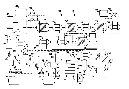
FIG. 1 schematically illustrates an embodiment of the present fuel
cell electric power generation system. In normal operation of fuel cell
power generation system 100, fuel from storage container 102 is
pressurized by pump 104 and supplied to fuel processing subsystem 108 at
a pressure from about 2750 kPa to about 4150 kPa, or more preferably
from about 3450 kPa to about 4150 kPa. The fuel is first directed to
preheater 110 where it is heated to about 300°C before introduction
into
autothermal reformer 112. A substantially pure oxygen stream from
oxygen supply container 114 is also supplied via line 116 and valve 117 to
10 autathermal reformer 1I2. Similarly, superheated steam is supplied from
vaporizer 118 to autothermal reformer 112, at about 600°C. In
autothermal reformer 112, the fuel, oxygen and steam are catalytically
reformed into a hydrogen-rich reformats stream comprising hydrogen,
carbon dioxide (COZ), carbon monaxide (CO), and water vapor, and that
15 may farther comprise HZS, some unreacted fuel and trace CZ-C6 fuel
combustion/cracking by-products.
Autothermal reformer 112 is typically operated at temperatures in
the range of about 850°C to about 1050°C, preferably about
970°C, to
ensure substantially complete conversion of methane and heavy and
20 intermediate hydrocarbon products (such as C2 and C6 hydrocarbons, for
example) in the reformats stream. To increase system efficiency,
autothermal reformer 112 is preferably operated at a steam-to-carbon ratio
in the range of about 2 to about 3, more preferably about 2.5.
The reformats stream exits autothermal reformer i 12 at
25 temperatures in the range from about 870°C to about 1300°C,
preferably
from about 900°C to about 1000°C. The operating temperature of
reformer I12 is maintained within the desired range by controlling the
amount of oxygen supplied to reformer 112 so that the oxygen-to-carbon
ratio is in a range of about 0.3 to about 0.5, more preferably about 0.4.
30 Valve 120 controls and maintains the amount of oxygen supplied to
reformer 112 from oxygen supply container 114 in response to the catalyst
CA 02352057 2001-05-28
WO 01/25140 PCT/CA00/01145
-13-
bed temperature of reformer 112, which is measured by temperature sensor
122 disposed therein.
The reformats stream is then directed to vaporizer I18 where it
heats a waterlsteam mixture flowing therethrough by heat exchange.
Alternatively, vaporizer I Z8 and autothermal reformer I I2 may be
integrated in a single vessel, if desired.
The reformats stream exits vaporizer I I8 and is supplied to H2S
scrubber 124. H2S scrubber 124 removes at least a portion of the HZS
from the reformats stream. Preferably, the size of H2S scrubber 124 is
suitably chosen so as to remove substantially all of the HZS from the
reformats stream.
H2S scrubber 124 may comprise any suitable component for
removing H2S from a gas stream. For example, an absorbent bed
comprising a metal oxide may be used. In this regard, absorbent beds
comprising, for example, iron, zinc, nickel, copper, manganese, or
molybdenum oxides, or mixtures andlor mixed oxides of the foregoing,
may be employed. Examples of such metal oxide absorbent beds are
described in U.S. Patent Nos. 5,244,641, 5,277,351, 5,769,909, and
5,792,438. As another example, hot carbonate HZS scrubbers, such as
described in U.S. Patent No. 4,297,330, may also be employed. Zn(J
absorbent beds are preferred.
The reformats stream then exits HZS scrubber 124 and is directed to
shift precooler 126 where the reformats stream is cooled by heat exchange
with water flowing through shift precooler 126 to a temperature within the
operating temperature range of shift reactor I28.
The reformats stream exiting shift precooler 126 is supplied to the
inlet of shift reactor 128, which camprises a shift catalyst bed and heat
exchange elements associated therewith that are fluidly isolated from the
catalyst bed. Preferably, shift reactor I28 is sized so that the shift
catalyst
bed is provided with an upstream sacrificial adiabatic bed for absorbing any
remaining HZS in the reformats stream not removed by HzS scrubber 124.
CA 02352057 2001-05-28
WO 01/25140 PCTJCA00/01145
-14-
More preferably, the sacrificial adiabatic bed is designed for easy removal
and replacement during maintenance.
In shift reactor 128, carbon monoxide is combined with water in the
catalyst bed to yield carbon dioxide and hydrogen according to the water
gas shift reaction:
CO + HZO ~ C02 + H2
The reaction is exothermic, requiring some sort of temperature
10 control to maintain the shift catalyst bed within a suitable operating
temperature range. In the present embodiment, the reformate exiting shift
reactor 128 is supplied to shift intercooler 130 where the reformats stream
is cooled by heat exchange with water flowing through shift intercooier
130. The cooled reformats stream is then redirected to the heat exchange
elements of shift reactor 128 in order to moderate the temperature of the
catalyst bed by heat exchange. Alternatively, water or another suitable heat
exchange fluid could be directed through heat exchange elements of shift
reactor 128 directly, in which case shift intercooler 130 could be
eliminated. Such heat exchange elements could be external and separate
20 from shift reactor 128, or may by integrated in the reactor vessel, if
desired.
Water is the preferred primary heat exchange fluid for fuel
processing subsystem 108. Water from water supply 132 is pressurized by
pump 134 and supplied to shift intercooler 130, where it is circulated and
heated by heat exchange with the reformats stream in shift intercooler 130.
The water stream exits shift intercooler 130 and is supplied to shift
precooler 125 where the water is further heated by heat exchange with the
reformats stream. The water stream is then supplied to prevaporizer 13b
and is at least partially converted into steam therein to produce a
30 water/steam mixture. The waterJsteam mixture is then supplied to
vaporizer 118, where it is converted to steam and superheated before
introduction into autothermal reformer 112, as described.
CA 02352057 2001-05-28
WO 41/25144 PCTlCA40101145
-15-
Other heat transfer fluids may also be employed as the heat
exchange fluid in fuel cell electric power generation system 100, such as
thermal oils, for example. Where a heat transfer fluid other than water is
employed, however, water will still need to be supplied to prevaporizer 136
5 and vaporizer I I8, of course. In addition, while the present fuel cell
electric power generation system is illustrated with the fuel processing
subsystem having heat exchange elements arranged in staggered series,
other heat exchange fluid flowpath configurations may also be employed, as
desired.
The reformate stream exiting shift reactor 128 is then supplied to
hydrogen separator preheater 138, where it is heated to a desired
temperature preferably within a suitable operating temperature range of
hydrogen separator 140. The heated reformate stream exits preheater 138
and is supplied to hydrogen separator 140, where the reformate stream is
15 separated into a substantially pure hydrogen fuel stream and a raffinate
stream. Hydrogen separator 140 comprises at least one hydrogen
separation membrane. In operation the reformate stream entering hydrogen
separator 140 is at a pressure from about 2750 kPa to about 4150 kPa, or
more preferably from about 3450 kPa to about 4150 kPa. The raffinate
20 stream is also at a pressure from about 2750 kPa to about 4150 kPa, or
more preferably from about 3450 kPa to about 4150 kPa, whereas the
hydrogen stream exiting hydrogen separator 140 is at a pressure less than
about 700 kPa, and preferably in the range of about 120 kPa to about 550
kPa.
25 The hydrogen separation membranes) of hydrogen separator 140
may comprise: a metal membrane (for example, palladium, palladium
alloy, or titanium alloy membrane); a polymeric material (for example,
porous or microporous polyaramides, polyimides, polyketones,
polysulfones, siloxane- and silane-based polymers, and cellulose acetate-
30 based polymers); ceramic membranes (for example, porous silica
membranes, porous or dense metal oxide membranes); zeolite molecular
sieves; carbon molecular sieves; and inorganic poly-acids (for example,
CA 02352057 2001-05-28
WO 01/25140 PCT/CA00/01145
-16-
poly-antimonic acids and polyphosphates); and composite membranes
thereof. The membranes may be supported or unsupported. They may be
flat films or films of various other shapes, such as cylinders, for example.
The membranes may comprise modules such as, for example, plate-and-
frame, spiral wound, or hollow fiber modules. Supported thin film metal
diffusion membranes of palladium or palladium alloy are preferred.
The substantially pure hydrogen stream exiting hydrogen separator
140 is supplied as a fuel stream to line 142, which is controlled by valve
144, and directed to fuel loop 146. Pressure regulating valve 144 controls
IO the amount of hydrogen supplied to fuel loop 146 from hydrogen separator
140 in response to the pressure within fuel loop 146 downstream of valve
144. The amount of reactants supplied to autothermal reformer 112 is also
controlled in response to the amount of hydrogen in the fuel stream, as
measured by hydrogen pressure sensor 145.
The fuel stream is first directed to humidifier 148 and humidified
therein. The humidified fuel is then supplied to fuel cell stack 150 at a
pressure less than about 700 kPa, and preferably in the range of about 120
kPa to about 550 kPa, where it is circulated through the anodes of the fuel
cells comprising stack 150 (not shown).
Fuel cell stack 150 comprises a plurality of fuel cells electrically
connected in series, in parallel, or in a combination thereof, to provide a
desired overall voltage and power output of the system. Fuel cell stack 150
may be an array comprising a plurality of fuel cell stacks. Any suitable
fuel cells may be employed, such as alkaline, phosphoric acid, or solid
polymer electrolyte fuel cells, for example. Solid polymer electrolyte fuel
cell stacks are preferred. Fuel cell stack 150 produces DC power; fuel cell
electric power generation system 100 may further comprise a power
conversion device (not shown). For example, system 100 may further
comprise a DG-DC power converter for converting unregulated DC power
to regulated DC power. As another example; system 100 may further
comprise a power inverter for converting the DC power output of stack 150
to AC power, if desired.
CA 02352057 2001-05-28
WO 01!25140 PCT/CA00101145
- 17-
The anode exhaust stream exiting stack 150 enters knock-out drum
152 to condense and collect liquid water from the exhaust stream. The
exhaust stream is then pressurized in pump 154 before being supplied to
line 142 for recirculation through stack 150. Because the fuel stream is
S substantially pure hydrogen, it may be recirculated through the stack via
fuel loop 146 for prolonged operating periods without significant
accumulation of inerts or impurities in the loop. However, a purge valve
may be incorporated into fuel loop I46, if desired, to provide the facility to
occasionally purge or bleed fuel Ioop 146, such as during surface
operations, for example.
A substantially pure oxygen stream is supplied from oxygen supply
container 114 via valve 1S6 to oxidant loop 158. To control the voltage
output of fuel cell stack 150, the concentration of oxygen within oxidant
loop 1S8 may be varied in response to the demands of the electrical load on
the system. Preferably, an inert gas stream from inert gas supply 160 is
mixed with the substantially pure oxygen stream to produce an oxidant
stream comprising 20 % to 100 % oxygen, preferably 20 % to 60 % oxygen.
"Inert gas" means a gas stream comprising a gas that is substantially
unreactive in the fuel cell stack, the fuel processing system, or both:
suitable inert gases include nitrogen, argon, helium, or carbon dioxide, or
any combination thereof, for example (carbon dioxide is considered an inert
gas in the fuel cell stack if supplied thereto to the exclusion of hydrogen).
Nitrogen and argon are preferred inert gases for use in oxidant loop 158.
Oxidant loop 158 may be precharged with inert gas to half the full power
design pressure, to ensure that the oxygen concentration at full power is
only about 50 % . A fixed quantity of inert gas may thus be recirculated,
with varying partial pressures of oxygen.
The oxidant stream in oxidant loop 158 is directed to humidifier 162
and humidified therein. The humidified oxidant stream is then directed to
fuel cell stack 150 at a pressure less than about 700 kPa, and preferably in
the range of about 120 kPa to about 550 kPa, where it is circulated through
the cathodes thereof (not shown). The cathode exhaust stream exiting stack
CA 02352057 2001-05-28
WO 01/25140 PCT/CA00101145
_ Ig _
150 enters knock-out drum 164 to condense and collect liquid water from
the exhaust stream. The cathode exhaust stream is then pressurized in
pump 166 before being mixed with the oxidant stream and supplied to
humidifier 162 for recirculation through stack 150. Oxidant loop 158 may
5 also further comprise a purge valve, if desired, to provide the facility to
occasionally purge or bleed oxidant Loop 158, such as during surface
operations, for example.
The raffinate stream exiting hydrogen separator 140, which
comprises hydrogen, C02, water vapor, and a small amount of unreacted
10 methane, and may further comprise trace CO andlor CZ-C6 fuel
combustion/cracking by-products, is directed to via valve 168 to catalytic
burner 170 at a pressure from about 2750 kPa to about 4150 kPa, or more
preferably from about 3450 kPa to about 4150 kPa. The raffinate stream is
mixed with an oxidant stream and combusted within the catalyst bed of
15 burner 170 (not shown). A substantially pure oxygen stream is supplied to
burner 170 from oxygen supply container 114 via Line 172, which is
controlled by valve 174. Oxygen is also supplied to burner 170 via oxygen
recovery loop 178 (discussed below). The combustion gases exit burner
170 as a burner outlet stream.
20 The burner outlet stream exiting burner 170 is supplied to
prevaporizer 136 where it is cooled by heat exchange with the waterlsteam
mixture circulating therein. The burner outlet stream is then supplied to
hydrogen separator preheater I38 and greheater 110, respectively, and
further cooled by heat exchange, before being supplied to oxygen recovery
25 loop 178.
Oxygen recovery loop 178 comprises condenser I80, COZ scrubber
182, and recycle blower 184. The cooled burner outlet stream enters
condenser 180 where liquid water from the gas stream is condensed and
collected. The burner outlet stream exiting from condenser 180 is then
30 directed to COZ scrubber I82 at a pressure from about 2750 kPa to about
4150 kPa, or more preferably from about 3450 kPa to about 4150 kPa.
The pressure of the burner outlet stream allows the C02 contained therein
CA 02352057 2001-05-28
WO O1I25140 PCTICA00101145
-19-
to be readily dissolved in a seawater stream directed through COz scrubber
182 by a pump (not shown) at diving depths and discharged from the vessel
without increasing the pressure of the burner outlet stream through a
romping-up process. A significant parasitic load associated with
conventional submarine electric power generation systems is thereby
eliminated. Further, Iow-pressure C02 scrubbers are significantly larger
than high-pressure COZ scrubbers. The pressure of the burner outlet
stream, by allowing use of a high-pressure CO2 scrubber, may also
decrease the size of the overall system, as well.
The burner outlet stream also typically comprises about 3-4 %
oxygen, which does not dissolve in the seawater within C02 scrubber 182
to any appreciable extent. Instead, the oxygen is collected and supplied to
recycle blower 184, where is it pressurized and supplied to catalytic burner
170 at a pressure from about 2750 lcPa to about 4150 lcPa, or more
15 preferably from about 3450 kPa to about 4150 kPa. Valve 174 controls
and maintains the amount of oxygen supplied to burner 170 from oxygen
supply container 114 in response to the concentration of oxygen in the
burner outlet stream, which is measured by oxygen sensor 186. As oxygen
is consumed in burner 170, valve 174 provides additional oxygen to
20 maintain the oxygen concentration in the burner exhaust stream at a level
within a predetermined range. Thus, oxygen recovery loop 178 allows for
efficient discharge of exhaust COZ while recovering oxygen in the burner
outlet stream that may be lost in conventional submarine electric power
generation systems. In air-independent propulsion applications, this may
25 provide for a longer submerged mission duration, as the oxygen supply
source tends to be the limiting factor in air-independent propulsion systems.
On start-up of the present fuel cell electric power generation system,
an inert gas, preferably CO2, is heated and cycled through the fuel
processing components in order to pre-heat them. For example, in fuel cell
30 electric generation system 100 of FIG. 1, pressurized COZ from COZ supply
188 is supplied via valve 190 to charge fuel processing subsystem I08 with
a predetermined volume of COZ. Once fuel processing subsystem is
CA 02352057 2001-05-28
WO 01/25140 PCTICA00101145
-20-
charged, valve 190 closes. The COZ will be circulated through fuel
processing subsystem for heating. The C02 flows through fuel processing
subsystem 108, through hydrogen separator preheater 138, and into
hydrogen separator 140. The COZ stream exits hydrogen separator 140 and
5 is supplied via 3-way valve 168 to recycle cooler 192. Recycle cooler 192
assists in maintaining the temperature of the inert gas stream within a
desired range by cooling it, as desired, in heat exchange with water flowing
through recycle cooler 192 (water source and circulation not shown). The
C02 stream exits recycle cooler 192 and is directed to recycle compressor
10 196. The CO2 stream then exits recycle compressor 196 and is directed to
prevaporizer 136 and from there to vaporizer 1I8 and autothermal reformer
112 to complete the start-up inert gas loop. During start-up fuel and
oxygen are not supplied to fuel processing subsystem 108, nor is heat
exchange fluid circulated therethrough.
15 Fuel from start fuel supply 198 is then supplied to burner 170.
(While start fuel supply 198 is illustrated as separate from fuel supply 102,
it is to be understood that start fuel supply 198 and fuel supply 102 may
represent the same fuel source or independent sources of fuel.) Preferably,
start fuel supply 198 and fuel supply 102 are the same. A substantially
20 pure oxygen stream is also supplied from oxygen supply container 114 via
line 172 to burner 170, as well as recycled burner exhaust stream from
oxygen recovery loop 178, as previously described. The fuel and oxidant
stream are mixed and combusted within burner 170; combustion may be
initiated catalytically or if cold burner 170 may further comprise a pilot
25 burner, ignitor, or similar such mechanism for initiating combustion. The
combustion gases exit burner 170 as a burner outlet stream and are directed
to prevaporizer i36 where the burner outlet stream heats the C02 stream in
the inert gas loop by heat exchange. The burner outlet stream is also
directed through hydrogen separator preheater 138, fuel preheater 110, and
30 condenser 180, as described previously. The burner outlet stream is then
diverted by valve 200 to recycle blower 184 (bypassing COZ scrubber 182)
and supplied to burner 170. The recycle rate of the burner outlet stream is
CA 02352057 2001-05-28
WO 01/25140 PCTJCA00101145
-21-
preferably controlled so as to moderate the flame temperature of burner
170 and thus moderate the rate of heating of the components of fuel
processing subsystem 108 during start-up.
Heating of the components of fuel processing subsystem 108 by the
recycled inert gas continues until at least a portion of them reach desired
initial operating temperatures, which may be less than the corresponding
minimum normal operating temperature for the component. Once this state
is reached, valve 168 directs the flow of the heated inert gas directly to
burner i70 and recycle blower 196 is shut off, stopping the flow of C02 in
10 the start-up inert gas loop. This is the "hot standby" state of fuel cell
electric generation system 100. Once a hot standby state has been
achieved, it may be maintained as desired by starting recycle blower 196
and initiating flow of CO2 in the start-up inert gas loop.
The start-up process continues by supplying fuel, oxygen, and steam
to autothermal reformer 112, as described previously. Ignition of the fuel-
oxidant-steam mixture within autothermal reformer 112 may be achieved
cataiytically or autotherrnal reformer 112 may further comprise a pilot
burner, ignitor, or similar such mechanism for initiating combustion.
Autothermal reformer 112 pressurizes and is heated to normal operating
20 temperature. Once autothermal reformer 112 reaches normal operating
temperature, valve 200 is adjusted to permit flow of the burner outlet
stream to COZ scrubber 182, and normal operation of fuel cell electric
power generation system 100 is initiated.
Alternatively, conventional means for heating the present fuel cell
electric power generation system during start-up could be used, such as
electric heating elements disposed within the fuel processing components.
Such conventional methods may be less desirable in certain applications,
since electric heating elements tend to heat the fuel processing components
unevenly, which may result in mechanical stresses placed on the
30 components, and they are a drain on battery power. The described start-up
sequence used to heat the fuel processing components of the present fuel
cell electric power generation system is preferred as it tends to heat up the
CA 02352057 2001-05-28
WO 01/25140 PCTICA00/01145
-22-
fuel processing components mare evenly, reducing stress on equipment,
and minimizes use of battery power.
A typical shutdown sequence for fuel cell electric power generation
system I00 involves purging the system with an inert gas and cooling of
fuel processing subsystem 108. For example, shutdown may be initiated
by interrupting supply of oxygen and fuel to fuel processing subsystem 108
by closing valve lI7 stopping pump 104, respectively. Steam is preferably
supplied to autothermal reformer 112 at a suitably low purge flow rate.
Inert gas is then supplied to fuel processing subsystem from C02 supply
10 188, as described previously. The pressure in autothermal reformer 112,
and fuel processing subsystem 108, drops as remaining hydrogen and COZ
therein are consumed. After substantially ail of the hydrogen within fuel
processing subsystem 108 is consumed, supply of steam to autothermal
reformer I12 is interrupted and the remaining steam in fuel processing
15 subsystem 108 is purged with COz. Once the fuel processing subsystem is
substantially flushed with inert gas, COZ flow is interrupted and fuel
processing subsystem I08 is allowed to cool, completing the shutdown
process.
While the present fuel cell electric power generation system is
20 described employing No. 2 diesel as fuel, other fuels are also suitable,
such
as gasoline or other grades of diesel. For example, low-sulfur diesel could
be employed. The use of low-sulfur diesel, for example, may result in a
reduced maintenance cycle for the fuel processing subsystem, in particular
the Zn0 bed or other HZS scrubbing components, andlor may permit the
25 use of smaller H2S scrubbing components. As another example, zero-sulfur
liquid synthetic hydrocarbon fuels could also be employed. The main
advantage of employing such fuels may include elimination of HZS
scrubbing components from the fuel processing subsystem, ease of
reforming, and reduction in the maintenance cycle andlor size of the shift
30 reactor. The main disadvantage with using such alternate fuels is primarily
their lack of ready availability.
CA 02352057 2001-05-28
WO OI/25140 PCTlCA00/01145
_23_
In the present fuel cell electric power generation system, the oxygen
supply may comprise liquid oxygen, air, or another oxygen source such as
hydrogen peroxide; for example. Where the oxygen supply comprises air,
an inert gas source may not be required in the oxidant supply loop. Where
5 the oxygen source comprises hydrogen peroxide, the system will further
comprise a decomposer for converting the hydrogen peroxide to an oxygen
stream.
As stated above, the preferred operating pressure for fuel processing
subsystem 108 is from about 2750 kPa to about 4150 kPa, or mare
10 preferably from about 3450 kPa to about 4150 kPa. In submarine
applications, the operating pressure of fuel processing subsystem 108 may
be controlled by a pressure regulator that is responsive to depth pressure.
The regulator may be set, for example, to maintain the pressure in a
preferred high pressure range; (such as 2750 kPa to 4150 kPa) even at
15 substantially lower depth pressures, or at Ieast at a minimum pressure
which is preferred for operation of hydrogen separator 140. The regulator
may however be adjusted, for example, to maintain the operating pressure
of fuel processing subsystem 108 at a variable pressure which is a fixed
amount higher than depth. pressure, thus the fuel processing subsystem 108
20 may be operated at Iower pressures than 2750 kPa at shallower depths. In
other applications, the operating pressure of fuel processing subsystem 108
may be set at any minimum pressure which is preferred for operation of the
hydrogen separator 140.
The system illustrated in FIG. 1 may be modified for submarine
25 applications to allow it to operate on atmospheric air during surface
operations, in addition to the oxygen supply which is used as the oxygen
source when the submarine is submerged. This conserves the oxygen
supplies, and can reduce or eliminate the need to maintain on-board diesel
generators andlor battery banks, thereby reducing the size and complexity
30 of the submarine power plant. The atmospheric air could, for example, be
compressed using a turbo-compressor mechanically connected to a turbo-
expander, which in turn would receive energy from the burner outlet
CA 02352057 2001-05-28
WO 01!25140 PCTICA00101145
-24-
stream. In this made of operation, compressed atmospheric air would be
directed to the fuel cell stack. The oxygen-depleted oxidant exhaust stream
from the fuel cell stack would be directed to the catalytic burner inlet (not
recirculated through the stack}, and the burner outlet stream would be
discharged to the atmosphere via the turbo-expander. In this manner, the
present fuel cell electric power generation system rnay also be employed in
stationary electric power generation applications, and in other vehicular
applications, such as surface ships, trains, and industrial and heavy-duty
vehicles, for example, where air-independent propulsion systems are not
required and there is no corresponding requirement for on-board oxygen
storage.
While particular elements, embodiments and applications of the
present invention have been shown and described, it will be understood, of
course, that the invention is not limited thereto since modifications may be
i5 made by those skilled in the art, particularly in light of the foregoing
teachings. it is therefore contemplated that the appended claims cover such
modifications as incorporate those features that come within the scope of
the invention.