Language selection

Search

Patent 2352444 Summary

Third-party information liability

Some of the information on this Web page has been provided by external sources. The Government of Canada is not responsible for the accuracy, reliability or currency of the information supplied by external sources. Users wishing to rely upon this information should consult directly with the source of the information. Content provided by external sources is not subject to official languages, privacy and accessibility requirements.

Claims and Abstract availability

Any discrepancies in the text and image of the Claims and Abstract are due to differing posting times. Text of the Claims and Abstract are posted:

  • At the time the application is open to public inspection;
  • At the time of issue of the patent (grant).
(12) Patent: (11) CA 2352444
(54) English Title: SWAB WITH PULL-TRUDED FIBER TIP
(54) French Title: TAMPON A EXTREMITE A FIBRES TIREES
Status: Term Expired - Post Grant Beyond Limit
Bibliographic Data
(51) International Patent Classification (IPC):
  • A46B 05/00 (2006.01)
  • B08B 11/00 (2006.01)
(72) Inventors :
  • KAMMERER, K. SCOTT (United States of America)
  • FORREST, EDWARD J., JR. (United States of America)
(73) Owners :
  • ILLINOIS TOOL WORKS INC.
(71) Applicants :
  • ILLINOIS TOOL WORKS INC. (United States of America)
(74) Agent: FINLAYSON & SINGLEHURST
(74) Associate agent:
(45) Issued: 2005-05-24
(22) Filed Date: 2001-07-05
(41) Open to Public Inspection: 2002-01-24
Examination requested: 2001-07-05
Availability of licence: N/A
Dedicated to the Public: N/A
(25) Language of filing: English

Patent Cooperation Treaty (PCT): No

(30) Application Priority Data:
Application No. Country/Territory Date
09/621,722 (United States of America) 2000-07-24

Abstracts

English Abstract

A swab for cleaning electronic and electro-mechanical components includes a handle and a pull-truded fiber cleaning head. The handle is elongated and has a cleaning head end and a grasping end. The cleaning head end defines a securing region for securing the cleaning head to the handle. The cleaning head is formed from a plurality of fibers that are pulled through a die to compress the fibers into a substantially rigid, elongated cleaning head. The swab includes a tether to secure the swab and prevent inadvertent misplacement.


French Abstract

Un tampon pour le nettoyage de composants électroniques et électromécaniques comprend un manche et une tête de nettoyage de fibre pultrudée. Le manche est allongé et a une extrémité de tête de nettoyage et une extrémité de préhension. L'extrémité de tête de nettoyage définit une région de fixation pour fixer la tête de nettoyage au manche. La tête de nettoyage est formée à partir d'une pluralité de fibres qui sont tirées à travers une matrice pour comprimer les fibres dans une tête de nettoyage sensiblement rigide et allongée. Le tampon comprend une attache pour fixer le tampon et empêcher un égarement par inadvertance.

Claims

Note: Claims are shown in the official language in which they were submitted.

-7-
WHAT IS CLAIMED IS:
1. A swab, comprising:
a handle defining a longitudinal axis, the handle being elongated and having
a cleaning head end and a grasping end, the cleaning head end defining a
securing
region; and
a cleaning tip, the cleaning tip being formed from a plurality of fibers
formed by pulling the fibers through a die compressing the fibers into a
substantially rigid, elongated cleaning head, the cleaning head being secured
to the
handle at the cleaning head end, the handle and cleaning tip defining a
longitudinal
axis.
2. The swab in accordance with claim 1 wherein the cleaning tip is
formed from polyester fibers.
3. The swab in accordance with claim 1 wherein the cleaning tip is
secured to the handle by friction-fit.
4. The swab in accordance with claim 1 wherein the cleaning tip is
secured to the handle by heat.
5. The swab in accordance with claim 1 wherein the cleaning tip is
secured to the handle by an adhesive.
6. The swab in accordance with claim 1 wherein the cleaning tip is
secured to the handle by ultrasonic welding.

-8-
7. The swab in accordance with claim 1 wherein the handle is a hollow tubular
member defining a central bore and the cleaning tip is formed having a shape
and a
dimension for inserting into the central bore.
8. The swab in accordance with claim 1 including a tether secured to the
handle grasping end.
9. The swab in accordance with claim 8 wherein the handle is a hollow
tubular member defining a central bore and an end of the tether is inserted
into
the central bore.
10. The swab in accordance with claim 1 including a grip portion mounted
externally of the handle.
11. The swab in accordance with claim 10 including a tether mounted to the
swab at the grip portion.
12. The swab in accordance with claim 11 wherein a portion of the tether is
disposed between the grip portion and the handle.
13. The swab in accordance with claim 8 wherein the tether is permanently
mounted to the handle.
14. The swab in accordance with claim 8 wherein the tether is removably
mounted to the handle.

Description

Note: Descriptions are shown in the official language in which they were submitted.


CA 02352444 2001-07-05
Case No. 12328/78813 -1_
SWAB WITH PULL-TRUDED FIBER TIP
Field of the Invention
This invention pertains to a swab for cleaning. More particularly, the
invention pertains,to ~ swab having a tip or cleaning head portion that is
formed
from a pull-truded fibrous material and a. method for making such swabs.
Background of the Invention
Swabs are used in all manners of cleaning. For example, everyone will
recognize common cotton tipped swabs that are used for person hygiene and
care. Because of the compact and effective nature of these swabs, they have
been
adopted for use in numerous areas of technology and manufacture. One such
1 S area is the manufacture 'of electrical components and more specifically
connectors for use in the telecommunications industry.
One particular type of connector used in the telecommunications industry
is for use in fiber optic cables. In splicing or connecting fiber optic cable
sections to one another, a connector is used. A typical connector includes a
male
portion and a female portion. During assembly of these cable sections, it is
not
unusual for pieces of debris and/or ambient soils, such as pieces of fiber or
fiber
coating debris to be left within the ends of the connectors. It is also not
unusual
for light oils, such as fingerprint and other natural skin oils and synthetic
oils to
be found on the ends of the connectors. As will be recognized by those skilled
in the art, this debris and the oils can signif cantly degrade or prevent the
transmission capabilities of the cables across the connectors.
Numerous types of cleaning implements have been used, with some
degrees of success, to clean these particularly susceptible areas. It has,
however,
been observed that cleaning implements formed from non-particulate removing
materials may not be acceptable for use in these connectors. Specifically, it
has

CA 02352444 2001-07-05
-2-
been found that particulates can become lodged in and around the connectors,
thus adversely effecting the quality of the telecommunications signal.
In addition, it has been observed that these connectors can vary from one
type to another. For example, the connector female end can be formed as having
S a flat inner end surface, a concave surface or a convex surface. To this
end, it has
been found that regardless of the type of cleaning implement used, debris that
settles into and around corners and oils that are present in these areas of
the
connector devices cannot be adequately removed.
Moreover, many of the currently used cleaning devices use foam-based
cleaning heads. The foam portions of these devices can adversely affect the
fiber optic conductors or may scratch the microscopic conductors. In addition,
there are no currently known cleaning implements that can be used to clean the
inside diameter of fiber optic connector ferrules.
Accordingly, there exists a need for a swab-type cleaning device that can
be used for cleaning a variety of delicate, electrical and electro-mechanical
devices, and particularly fiber optic connectors. Desirably, such a device is
configured so that it can be used to clean narrow or small spaces, without
degrading when cleaning slots and the like in devices such as fiber optic
connectors, as well as junction regions of walls and/or surfaces. Most
desirably,
such a cleaning device removes contaminants, including particulate and light
oils without leaving any of its own debris, such as particulate or matter.
Summar~r of the Invention
A swab for cleaning for example, fiber optic connectors and electrical and
electro-mechanical components includes an elongated handle having a cleaning
head end and a grasping end, and a cleaning head secured to the handle. The
handle defines a longitudinal axis and defines a securing region.
The cleaning head or tip is formed from a plurality of fibers that are pulled
through a die to compress the fibers into the substantially rigid, elongated
cleaning

CA 02352444 2001-07-05
-3-
head. The cleaning head is secured to the handle at the cleaning head end. The
handle and cleaning tip define a longitudinal axis.
In a preferred embodiment, the cleaning tip is formed from polyester fibers.
Preferably, the handle is a hollow tubular member that defines a central bore
and
the cleaning tip is formed having a shape and a dimension for inserting into
the
handle bore. In this arrangement, the cleaning tip is secured to the handle by
friction-fit. Alternately, the cleaning tip is secured to the handle by heat,
by an
adhesive, by ultrasonic welding or the like.
The swab can include a tether secured to the handle grasping end. The
tether can be secured to the handle by insertion into the handle bore.
Alternately,
the tether can be attached to the handle by a grip portion mounted externally
over
the grasping end of the handle.
These and other features and advantages of the present invention will be
apparent from the following detailed description, in conjunction with the
accompanying drawings, and the appended claims.
Brief Description of the Fides
FIG. 1 is a plan view of a pull-traded fiber swab embodying the principles
of the present invention;
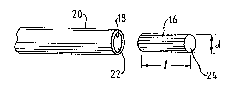
FIG. 2 is a partial, enlarged~view of the cleaning end portion of the swab
handle and a cleaning head or tip, showing .the dimensional relationship
between
the handle and the cleaning head;
FIG. 3 is a partial, enlarged view of the grasping end portion of the handle
and showing an optional tether affixed thereto by an internal plug; and
FIG. 4 is a partial, enlarged view of the grasping end portion of the handle
and showing the optional tether affixed thereto by an external grip mount.

CA 02352444 2001-07-05
-4-
Detailed Description of the Preferred Embodiments
While the present invention is susceptible of embodiment in various forms,
there is shown in the drawings and will hereinafter be described a presently
preferred embodiment with the understanding that the present disclosure is to
be
considered an exemplification of the invention and is not intended to limit
the
invention to the specific embodiment illustrated.
Referring to the figures and in particular FIG. l, there is shown a swab 10
having a pull-traded fiber tip 12 embodying the principles of the present
invention.
The swab 10 includes, generally, a handle 14 and a cleaning head portion 16.
The
I O cleaning head 16 is formed from a fibrous material that, in a present
embodiment, is
inserted into an opening I 8 in a tip securing end 20 of the handle 14 and
sealed
thereto.
In a current embodiment, the handle 14 is an elongated polypropylene
tubular member having an open central region or bore 22. The cleaning head 16
is
a pull-traded fibrous material. Pull-trading is similar to an extruding
process
except that rather than pushing the material through a die, the material is
pulled
through the die. In a present embodiment, a polyester material is pulled
through a
die to form the pull-traded fiber cleaning head 16. Pulling the fibrous
polyester
material compresses the fibers forming a relatively rigid composition. The tip
or
head I6 can then be cut to form, for example, a flat head 24 as illustrated in
FIG. 2,
an angled head (not shown), or other shapes as desired.
It is contemplated that the cleaning head I6 will be fabricated or pulled so
that it can, dimensionally, snuggly fit within the bore 22 of the handle 14.
Alternately, the cleaning head 16 can be mounted within the handle 14 and
sealed
thereto by, heat, ultrasonic welding, adhesive or the like.
The cleaning head 16 can be fabricated having a wide range of diameters d
from about 1.0 millimeters (mm) to about 3.0 mm and lengths 1, and a wide
range
of lengths from about 10 mm to about 30 mm. In a present embodiment, the
cleaning head or tip 16 has a diameter d of about 1.25 mm and a length 1 of
about

CA 02352444 2001-07-05
-5-
25 mm. Those skilled in the art will, however, appreciate the wide variety of
tip
16 diameters and lengths.
Although the present swab 10 can be used for various cleaning applications,
because of the rigidity of the cleaning head 16, and the ability to vary the
cross-
section shape and size of the head 16, it has been found that the present swab
10 is
particularly well suited for use in cleaning fiber optic cable connectors and
the like.
It has also been found that the because the size and shape of the head 16 can
be
varied, the present swab 10 is also particularly well suited for use in
cleaning fiber
optic connectors, ferrules and like equipment.
The swab 10 can be fitted with an optional tether 26 formed from, for
example, a flat woven low friction material. The tether 26 can be, for
example,
placed around a user's wrist so that the swab I O cannot be inadvertently left
or lost
in a delicate or controlled area. Use of the tether-attached swab 10 is
particularly
well suited for example, when cleaning equipment in aerospace applications.
The
tether 26 can be affixed to the swab handle 14 by inserting a plug 28 or like
element
(that is affixed to the tether 26) into the handle bore 22 at a handle
grasping end 30.
Alternately, heat or adhesive can be used to secure the tether 26 to the
handle 14.
To this end, the tether 26 can be made permanently affixed to the handle 14 or
removable from the handle 14.
The tether 26 can also be attached or mounted to the handle 14 by a
gripping portion 32 mounted over or externally of the handle 14, as shown in
FIG.
4. In this arrangement, the tether 26 can be inserted between the gripping
portion 32
and the handle 14, or directly attached to the grip 32. The grip portion 32
can be
formed from rubber or a like readily gripped, non-slip material. The grip 32
also
facilitates use of the swab 10 in a wide range of environmental conditions.
From the foregoing it will be observed that numerous modifications and
variations can be effectuated without departing from the true spirit and scope
of the
novel concepts of the present invention. It is to be understood that no
limitation
with respect to the specific embodiment illustrated is intended or should be

CA 02352444 2001-07-05
-6-
inferred. The disclosure is intended to cover by the appended claims all such
m~difications as fall within the scope of the claims.

Representative Drawing
A single figure which represents the drawing illustrating the invention.
Administrative Status

2024-08-01:As part of the Next Generation Patents (NGP) transition, the Canadian Patents Database (CPD) now contains a more detailed Event History, which replicates the Event Log of our new back-office solution.

Please note that "Inactive:" events refers to events no longer in use in our new back-office solution.

For a clearer understanding of the status of the application/patent presented on this page, the site Disclaimer , as well as the definitions for Patent , Event History , Maintenance Fee  and Payment History  should be consulted.

Event History

Description Date
Inactive: IPC expired 2024-01-01
Inactive: Expired (new Act pat) 2021-07-05
Common Representative Appointed 2019-10-30
Inactive: IPC from MCD 2006-03-12
Grant by Issuance 2005-05-24
Inactive: Cover page published 2005-05-23
Pre-grant 2005-03-15
Inactive: Final fee received 2005-03-15
Notice of Allowance is Issued 2004-09-23
Letter Sent 2004-09-23
Notice of Allowance is Issued 2004-09-23
Inactive: Approved for allowance (AFA) 2004-09-14
Amendment Received - Voluntary Amendment 2004-05-10
Inactive: S.30(2) Rules - Examiner requisition 2004-03-17
Amendment Received - Voluntary Amendment 2003-12-10
Amendment Received - Voluntary Amendment 2003-11-06
Inactive: S.30(2) Rules - Examiner requisition 2003-10-27
Inactive: S.29 Rules - Examiner requisition 2003-10-27
Inactive: Cover page published 2002-01-25
Application Published (Open to Public Inspection) 2002-01-24
Inactive: First IPC assigned 2001-09-04
Inactive: Filing certificate - RFE (English) 2001-08-01
Letter Sent 2001-08-01
Application Received - Regular National 2001-07-30
Request for Examination Requirements Determined Compliant 2001-07-05
All Requirements for Examination Determined Compliant 2001-07-05

Abandonment History

There is no abandonment history.

Maintenance Fee

The last payment was received on 2004-06-21

Note : If the full payment has not been received on or before the date indicated, a further fee may be required which may be one of the following

  • the reinstatement fee;
  • the late payment fee; or
  • additional fee to reverse deemed expiry.

Patent fees are adjusted on the 1st of January every year. The amounts above are the current amounts if received by December 31 of the current year.
Please refer to the CIPO Patent Fees web page to see all current fee amounts.

Owners on Record

Note: Records showing the ownership history in alphabetical order.

Current Owners on Record
ILLINOIS TOOL WORKS INC.
Past Owners on Record
EDWARD J., JR. FORREST
K. SCOTT KAMMERER
Past Owners that do not appear in the "Owners on Record" listing will appear in other documentation within the application.
Documents

To view selected files, please enter reCAPTCHA code :


To view images, click a link in the Document Description column. To download the documents, select one or more checkboxes in the first column and then click the "Download Selected in PDF format (Zip Archive)" or the "Download Selected as Single PDF" button.

List of published and non-published patent-specific documents on the CPD .

If you have any difficulty accessing content, you can call the Client Service Centre at 1-866-997-1936 or send them an e-mail at CIPO Client Service Centre.


Document
Description 
Date
(yyyy-mm-dd) 
Number of pages   Size of Image (KB) 
Representative drawing 2001-12-27 1 5
Claims 2003-11-05 2 54
Abstract 2001-07-04 1 19
Description 2001-07-04 6 280
Drawings 2001-07-04 1 20
Claims 2001-07-04 2 58
Claims 2004-05-09 2 56
Courtesy - Certificate of registration (related document(s)) 2001-07-31 1 112
Filing Certificate (English) 2001-07-31 1 163
Reminder of maintenance fee due 2003-03-05 1 107
Commissioner's Notice - Application Found Allowable 2004-09-22 1 160
Correspondence 2005-03-14 1 29