Note: Descriptions are shown in the official language in which they were submitted.
CA 02352596 2001-07-06
1673 GB
2001-06-08
VACUUM SEWER SY,~STEM
The invention relates to an arrangement in a vacuum sewer system
according to the preamble of claim 1.
In vacuum sewer systems it is known to use ejector devices for
generating vacuum. Systems like these are disclosed for example in patent
publications FI 63985 and EP 653524 / US 5,535,770. In these vacuum
sewer systems the ejector device is at the same time arranged to provide a
collecting container for the sewage coming from the sewer network. The sew-
age flow that is circulated by a pump from the collecting container is used as
the working medium of the ejector of the ejector device. The suction side of
the ejector is connected to the sewer network so that it generates partial vac-
uum in the sewer network, whereby the sewage coming from the sewer net-
work flows through the ejector into the collecting container. In practice this
means that the ejector discharges its working medium, that is the sewage flow
circulated by the pump, together with air sucked from the sewer network and
the sewage flow coming from the sewer network to the collecting container
under high pressure.
The function of the ejector causes foaming in the collecting con-
tainer due to the strong jet effect, which first of all is transferred to the
sur-
roundings through the overflow pipe of the collecting container, through the
ventilation duct and through possible leaks and secondly is transferred into
the
circulation process of the ejector lessening the degree of efficiency of
vacuum
generation. The foaming causes problems with the sewage volume in the col-
lecting container and with the monitoring of the state of the same, which can
damage the pump and lead to disturbances in the control functions of the vac-
uum sewer system. The behaviour of the foaming sewage is subject to random
changes and it may cause cavitation in the pump. The aforementioned circum-
stances also reduce the working life of the components of the device. Fur-
CA 02352596 2001-07-06
2
thermore, the opening of the device, for example in connection with mainte-
nance or repair, causes a discharge of dangerous gases.
The object .pf the present invention is to avoid the above mentioned
disadvantages and to achieve an arrangement that has a simple structure and
a reliable function. This object is attained by an arrangement according to
the
invention, the main features of which are given in claim 1.
The invention is based on the idea that a liquid driven ejector is used
in the vacuum sewer system, the circulation process of which is kept compact
and without disturbances, and that the sewage collecting process is kept sub-
stantially separate from the circulation process of the ejector device so that
the sewage and its treatment do not directly have an effect on the vacuum
generation in the sewer system, i.e. on the ejector device.
The vacuum generation provided by the ejector device forms a pri-
mary circuit and the sewage collecting process a secondary circuit.
The main components of the ejector device advantageously com-
prise to their substantial parts a container, in which substantially normal at-
mospheric pressure prevails, an ejector, circulation means for the liquid func-
tioning as a working medium of the ejector and a suction connection con-
nected to suction side of the ejector, which suction connection is connected
to
the sewer network.
In the vacuum sewer system, on the side of the sewage collecting
process, a collecting container, to which the suction connection of the
ejector
device is connected, connected to the sewer network is advantageously used.
The circulation means of the liquid functioning as a working medium
of the ejector advantageously comprise a circulation pump, particularly a cen-
trifugal pump. The liquid functioning as the working medium may advanta-
geously be water, which has been blended for neutralising the harmful effects
of the sewage, particularly of the gases formed therefrom.
The ejector container is advantageously provided with sensor means
connected to a control center for monitoring the surface level of the liquid
CA 02352596 2001-07-06
3
functioning as the working medium of the ejector. In this way a stable and ef-
ficient functioning of the circulation means and the ejector may be ensured.
In order to ensure the functioning of the sewage collecting process,
i.e. the secondary circuit, the sewage collecting container is advantageously
provided with emptying means and sensor means for monitoring the surface
level of the sewage.
The emptying means for the collecting container advantageously
comprise a circulation pump, particularly a centrifugal pump.
By using separate, advantageously similar means, both as the circu-
lation means for the ejector device and as the emptying means for the collect-
ing container, these may be advantageously be cross-coupled so that they are
alternatively usable when one is e.g. damaged, in maintenance or replaced.
Alternatively the same means may be used as the circulation means
for the ejector device and as the emptying means for the collecting container,
which for example in smaller vacuum sewer systems may be advantageous in
view of costs.
The sewage collecting container advantageously forms an intermedi-
ate container, whereby the vacuum sewer system further comprises for exam-
ple a sewage container for storing the sewage for a desired time.
The sewage collecting process covers the transfer of sewage from
the source of sewage to the sewer network and the transport of sewage to a
possible circulation, treatment, storage or other discharge space, for example
via an intermediate collecting container.
The sewage may comprise grey water, i.e. for example waste water
and/or solid waste from a wash room, and black water, i.e. for example waste
water and/or solid waste from a toilet unit. The vacuum sewer system may
also be used for example in connection with supermarkets or corresponding
sites, in which in addition to the above mentioned other sewage of different
types are found. The sewage may be grey water comprising for example
waste from meat or fish treatment utilities which usually firstly has to be
transferred to a treatment plant before its further transport. Furthermore,
con-
CA 02352596 2001-07-06
4
densate from refrigerators or freezers may come in question, which, if so de-
sired, may recirculated for use as flush water for example for a toilet unit.
The invention also relates to an ejector device, which is intended for
generating vacuum in a vacuum sewer system. The characterising features of
the ejector device according to the invention are given in claim 12 and its ad-
vantageous embodiments in claims 13 to 16.
In the following the invention is described more in detail, by way of
example only, and with reference the accompanying schematic drawings, in
which:
Fig. 1 shows a process diagram of a vacuum sewer system;
Fig. 2 shows a first embodiment of the ejector device and the col-
lecting container;
Fig. 3 shows a second embodiment of the ejector device and the
collecting container; and
Fig. 4 shows a third embodiment of the ejector device and the col-
lecting container.
In the vacuum sewer system shown in Fig. 1 the ejector device is
generally indicated by reference numeral 1, the sewer network by reference
numeral 2 and the circulation, treatment, discharge or storage space far the
sewage coming from the sewer network by reference numeral 3.
The ejector device 1 comprises an ejector 4 with a suction connec-
tion connected to the sewer network 2, an ejector container 5 under substan-
tially normal atmospheric pressure provided with a ventilation pipe 6 and cir-
culation means, which comprise a circulation pump 7, which advantageously is
a centrifugal pump. In the ejector container 5 a certain supply of liquid is
main-
tained, which is monitored by sensor means 9 and 10 connected to a control
center 1 1 for monitoring the surface level of the liquid. Liquid is sucked
through the liquid transport pipe 8 from the ejector container 5 by the
circula-
tion pump 7 and supplied to the ejector 4, which discharges the liquid with
high pressure back to the ejector container 5. Air is sucked in a manner known
per se from the sewer network 2 through the suction pipe 22 by the ejector 4,
CA 02352596 2001-07-06
i.e. through its suction connection connected to the sewer network 2. This
procedure provides a vacuum in the sewer network, which preferably is in the
range of about =0.3 to, -0.7 bar, mostly in the range of about -0.4 to -0.6
bar.
The liquid functioning as the working medium of the ejector 4 ad-
vantageously is water, which when necessary can be treated with chemicals
in order to prevent harmful effects from the sewage in the sewer network 2.
Water is an economical and environmentally friendly substance, and further-
more, it may easily be treated so that the harmful effects of contamination,
i.e. the corrosive effects on the ejector device 1 and any undesirable odors,
from the sewage or from the gases developing from it easily may be neutral-
ised.
The circulation process of the ejector, i.e. of the vacuum generation,
is consequently substantially closed, except for the suction connection con-
nected to the sewer network, and forms a primary circuit, which is separated
from the secondary circuit of the vacuum sewer system, i.e, the sewage col-
lection process. This makes it possible to keep the liquid supply as small as
possible. When for example substantially clean water is used as a liquid, its
circulation and discharge does not cause foaming or any other factors that dis-
turb the function of the ejector device. As an example may be mentioned that
when using one ejector the supply of liquid can be in the range of about 100
liters, whereby there is no actual upper limit.
The number of ejectors can be chosen according to the need for
vacuum generation in the sewer network in each case.
The liquid may be something else than water, whereby the liquid ad-
vantageously is chosen so that the above mentioned objectives are attained.
The secondary circuit of the vacuum sewer system, i.e. the sewage
collecting process, mainly comprises the sewer network 2 and the sewage cir-
culation, treatment, storage or other discharge space 3, and advantageously
an intermediate collecting container 32 arranged before said space.
CA 02352596 2001-07-06
6
The sewer network 2 according to the given example may comprise
one or more sources of sewage, although in the diagram of Fig. 1 only a vac-
uum toilet 24 arid a thereto connected source of flush water 26 are shown.
Sewage from a vacuum toilet unit is usually categorised as black water. Fur-
thermore, the sewer network may comprise for example wash basins, show-
ers, etc., which are not shown in Fig. 1 and from which the above mentioned
grey water originates. The vacuum toilet unit 24 is connected to sewer piping,
i.e. to the vacuum piping 28, through a valve means. From the vacuum toilet
unit 24 the vacuum piping 28 leads to the sewage collecting container 32.
As has been described above, a vacuum of a certain magnitude is
generated in the sewer network 2 by the ejector device 1, i.e. in this case
through the suction connection connected to the suction side of the ejector 4
and through the pipe 22 directly to the collecting container 32 in order to
pro-
vide for transportation of the sewage coming from the vacuum toilet unit 24
through the vacuum piping 28 to the collecting container 32. The vacuum
piping 28 is provided with a pressure transducer 30 and/or pressure gauge 34
connected to the control center 1 1 for monitoring the pressure level in the
vacuum piping 28 and collecting container 32. The collecting container 32 is
advantageously provided for example with sensor means 36 and 38 connected
to the control center 1 1 for monitoring the sewage surface level in the col-
lecting container and and/or with an observation window 40. The sewage col-
lecting container 32 in the described vacuum sewer system functions as an
intermediate container and it is provided with emptying means, which com-
prise a discharge valve 42 and emptying means 44, for example a circulation
pump, which advantageously may be a centrifugal pump.
In so far as the circulation means for the liquid functioning as the
working medium of the ejector 4 and the emptying means for the collecting
container both comprise a centrifugal pump, these can easily be cross-coupled
so that one can be used instead of the other according to need, for example in
case of damage or maintenance.
CA 02352596 2001-07-06
7
In connection with the emptying of the collecting container 32 used
as an intermediate container, the collecting container is set under
substantially
normal atmospheric pressure, for example through a ventilation pipe 46,
whereby the valve ~48 in the vacuum piping 28 is closed. The collecting con-
s tainer 32 is emptied through the discharge valve 42 by the circulation pump
44 to a discharge space under substantially normal atmospheric pressure, i.e.
in this case into a sewage container 50 provided with a ventilation pipe 52.
The sewage container 50 is also provided with emptying means, in the de-
scribed case with a discharge valve 54 and an overflow guard 56. The amount
of sewage collected in the sewage container 50 is monitored by a sensor
means 58 connected to the control center 1 1 for monitoring the surface level
of the sewage.
The collecting container 32 may also be arranged to be emptied into
a free discharge space, to a sewage treatment plant or into another selected
space depending on the type of sewage in question and in which connection
the vacuum sewer system is applied.
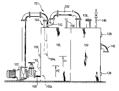
In Fig. 2 is shown a first embodiment of the ejector device and the
sewage collecting container, which may be applied to the above disclosed
vacuum sewer system.
The ejector device 101 comprises a centrifugal pump 107 to the
suction side of which is connected a transport pipe 108 for working medium
which is connected to the lower part of the ejector container 105, which is
under substantially normal atmospheric pressure. The centrifugal pump 107
circulates the liquid sucked from the ejector container 105 and functioning as
the working medium of the ejector 104 and feeds it with high pressure
through the ejector 104 back into the ejector container 105. In this way the
ejector 104 in a manner known per se draws air through a suction pipe 122 in
communication with a suction connection 1 13 connected to the suction side
of the ejector 104 from the sewage collecting container 132 and forms a par-
tial vacuum in the collecting container 132 and the vacuum piping 128 of the
CA 02352596 2001-07-06
sewer network. The ejector container 105 is provided with a ventilation pipe
106.
In this embodiment the ejector container 105 of the ejector device
and the sewage collecting container 132 are formed of two adjacent, vertically
arranged containers.
The ejector 104 is arranged in the upper part of the ejector container
105 so that it discharges the liquid from its discharge opening 104a down-
wards, from the upper part of the ejector container 105 towards its lower
part.
A certain liquid supply is maintained in the ejector container 105 monitored
by
sensor means 109 and 1 10 for monitoring the liquid surface level. The maxi-
mum height H 1 of the liquid surface level is advantageously kept below the
discharge opening 104a of the ejector 104 and the minimum height H2 above
the inlet opening 108a of the liquid transfer pipe 108, which forms the liquid
inlet of the centrifugal pump 107, whereby the liquid without disturbances can
transfer to the circulation pump 107 so that the function of the ejector 104
is
as efficient as possible.
The ejector device can also be arranged so that the ejector is ar-
ranged at the lower part of the ejector container, whereby the ejector dis-
charges the liquid upwards towards the upper part of the ejector container.
Also in an arrangement of this type the above given surface level limits are
valid.
The primary circuit formed by the ejector device 101 is substantially
closed, with exception of the suction connection. The liquid functioning as
the
working medium is advantageously water, which has been blended with ap-
propriate chemicals which neutralise the gases developed by the sewage col-
lected in the collecting container 132, whereby they do not cause harm to the
ejector device.
The sewage collecting container 132 is provided with a ventilation
pipe 146, an emptying valve 142 and sensor means 136 and 138 for moni-
toring the surface level of the sewage.
CA 02352596 2001-07-06
9
In Fig. 3 is shown a second embodiment of the ejector device and
the collecting container, which may be applied to the above disclosed vacuum
sewer system.
The ejector device 201 comprises a centrifugal pump 207 to the
suction side of which is connected a working medium transfer pipe 208 con-
nected to the lower part of the ejector container 205. The centrifugal pump
207 circulates liquid under substantially normal atmospheric pressure sucked
from the ejector container 205 and functioning as the working medium of the
ejector 204 and feeds it with high pressure through the ejector 204 back into
the ejector container 205. The ejector container 205 is provided with a
ventila-
tion pipe 206. In this way the ejector 204 through the suction connection 213
connected to its suction side sucks air in a manner known per se from the
sewage collecting container 232 and creates a partial vacuum in the collecting
container 232 and the vacuum piping 228 of the sewer network.
In this embodiment the ejector device 201 and the collecting con-
tainer 232 are arranged separate from each other.
The primary circuit formed by the ejector device 201 is substantially
closed, with the exception of the suction pipe connection. The liquid function-
ing as the working medium is advantageously water, which is blended with
appropriate chemicals which neutralise gases formed by the sewage collected
in the collecting container 232, whereby they do not cause damages to the
ejector device.
The sewage collecting container 232, which is shown vertically ar-
ranged, is provided with sensor means 236 and 238 for monitoring the surface
level of the sewage collected in the collecting container, as well as with a
dis-
charge valve 242 and a ventilation pipe 246.
The ejector container 205 has a substantially longitudinal configura-
tion with a cylindrical cross-section and it is horizontally arranged, whereby
the
ejector 204 discharges the liquid from its discharge opening 204a in the longi-
tudinal direction of the ejector container 205. The liquid transfer pipe 208
connected to the suction side of the centrifugal pump 207 is connected to an
CA 02352596 2001-07-06
opposite end of the ejector container 205 with regard to the ejector 204 and
it
runs inside the ejector container 205 near its lower edge, substantially to
the
ejector end of the ejector container 205. The liquid is arranged to be sucked
into the transfer pipe 208 from a suction slot 214 on its underside, which
5 forms the inlet of the centrifugal pump 207 and which extends to a distance
L
from the ejector end of the transfer pipe 208 towards the opposite end. The
suction slot 214 is advantageously at its broadest at the ejector end of the
transfer pipe 208 and narrows in the other direction, i.e. in the suction
direc-
tion. This has shown to be an advantageous arrangement for securing that the
10 liquid is sucked to the centrifugal pump and from there further on to the
ejec-
tor, thus avoiding that air is sucked into the liquid during the process. Any
ad-
ditional air could disturb the functioning of the arrangement.
The minimum height H2 of the liquid surface level in the ejector con-
tainer 205 is kept above the transfer pipe 208 which forms the inlet of the
working medium of the centrifugal pump 207, at least above the suction slot
204 of the transfer pipe 208, and the maximum level H 1 below the discharge
opening 204a of the ejector 204. The ejector container 205 is provided with
sensor means 209 and 210 for monitoring the liquid surface level.
The liquid jetting with high pressure from the ejector 204, however,
causes strong splashing in the ejector container 205 creating air bubbles in
the
liquid. In addition to the arrangement of the above described liquid transfer
pipe 208 comprising its suction slot 214, it has shown to be advantageous
that a structure 215, 216 dampening the movement of the working medium,
i.e. a structure dampening the splashing of the liquid, is formed above the
transfer pipe 208. Such a structure may for example be formed by overlapping
wings 215, opening away from the ejector 204, which receive the liquid flow
striking back from the end of the ejector container 205 opposite the ejector
204. The wings 215 advantageously extend over the whole width of the ejec-
tor container 205 and they may also be provided with downwards extending
front edges 216, which in turn stop the liquid flow returning from the wings.
CA 02352596 2001-07-06
11
In this manner a steady and disturbance-free function of the centrifugal pump
207 and the ejector 204 respectively may be ensured.
The ejecto~container 205 may further be provided with separation
means 217 shown by broken lines in order to separate air from the water. The
separation means 217 in this example are perforated plates 217 arranged at
the end of the ejector container 205 opposite the ejector 204. The perforated
plates 217 are advantageously arranged in an inclined position, for example at
an angle in the range of 45° with respect to the longitudinal direction
of the
ejector container 205.
In Fig. 4 is shown a third embodiment of the ejector device and the
sewage collecting container, which may be applied to the above disclosed
vacuum sewer system.
The ejector device 301 comprises a centrifugal pump 307 to the
suction side of which is connected a working medium transfer pipe 308 con-
nected to the lower part of the ejector container 305, which is under substan-
tially normal atmospheric pressure. The centrifugal pump 307 circulates the
liquid sucked from the ejector container 305 and functioning as the working
medium of the ejector 304 and feeds it with high pressure through the ejector
304 back into the ejector container 305. In this way the ejector 304 through
the suction pipe 213 connected to its suction side in a manner known per se
sucks air from the sewage collecting container 332 and creates a vacuum in
the collecting container 332 and the vacuum piping 328 of the sewer network.
The ejector container 305 is provided with a ventilation pipe 306.
In this embodiment the ejector container 305 of the ejector device
and the sewage collecting container 332 are formed into two containers ar-
ranged one on top of the other and in a horizontal direction.
The primary circuit formed by the ejector device 301 is substantially
closed, with exception of the suction pipe. The liquid functioning as the work-
ing medium is advantageously water, which is blended with appropriate
chemicals which neutralise the gases formed by the sewage collected in the
CA 02352596 2001-07-06
12
collecting container 332, whereby they do not cause damages to the ejector
device.
The sewage, collecting container 332 is provided with a ventilation
pipe 346, a discharge valve 342 and sensor means 336 and 338 for monitor
s ing the surface level of the sewage.
In the horizontal ejector container 305 the ejector 304 is arranged to
discharge liquid from its discharge opening 304a in the longitudinal direction
of
the ejector container 305. The minimum height H2 of the surface level of the
liquid in the ejector container 305 is kept above the inlet opening 308a of
the
transfer pipe 308, which forms the working medium inlet of the centrifugal
pump 307, and the maximum height H 1 below the discharge opening 304a of
the ejector 304. The ejector container 305 is provided with sensor means 309
and 310 for monitoring the surface level of the liquid.
This embodiment provides an example of having the same centrifu
gal pump used both as the circulation means 307 for the working medium of
the ejector 304 as well as as the discharge means 344 of the sewage collect
ing container 332.
The above described dampening structure and the perforated plates
used for avoiding splashing and formation of air bubbles are examples of how
to avoid air being transferred into the circulation means for the working me
dium of the ejector 204, comprising a centrifugal pump 207. Such means in-
crease the degree of efficiency of vacuum generation and ensure an appropri-
ate function of the centrifugal pump. These arrangements can be used to-
gether or separately. Corresponding structures can, if so desired, also be ap-
plied in connection with the embodiments shown in Figs. 2 and 4.
The above described three embodiments are only examples of possi-
ble applications of the invention. The objective is that the liquid circuit of
the
ejector device is closed, i.e. separate from the sewage collecting process,
that
the amount of liquid is kept as small as possible, that the state of the
liquid is
stabilised after discharge from the ejector, so that it is transferred to the
cir-
CA 02352596 2001-07-06
13
culation means in a stabile state without air bubbles etc., and that the size
of
the ejector device is kept as small as possible.
In connection with these three embodiments separate pumps may be
used as the circulation means for the ejector device and as the discharge
means for the sewage collecting container, as described in connection with
Fig. 1, or the same pump, as described in connection with Fig. 4. Instead of
the centrifugal pump mentioned any other suitable pump or device suitable for
the purpose may be used as a circulation means for the ejector device and as
the discharge means for the sewage collecting container.
The drawings and the description related thereto are only intended
for clarification of the idea of the invention. The invention may vary in
detail
within the scope of the ensuing claims.