Note: Descriptions are shown in the official language in which they were submitted.
CA 02352703 2001-07-09
2000-218509
-1-
DISPOSABLE PULL-ON UNDERCiARMENT
This invention relates to a disposable pull-on
undergarment and more particularly to a pull-on undergarment
such as a disposable pants-type diaper, training pants or
incontinent pants.
Conventional disposable pull-on undergarments are
composed of front and rear waist regions opposed to each other
and a crotch region extending between thE~se two waist regions .
The front and rear waist regions are connected with each other
in bonding zones extending along transversely opposite side
edge portions thereof so as to define a waist-hole and a pair
of leg-holes . Such undergarment is disc.7_osed, for example, in
Japanese Patent Application Publication Nos. 1998-75980A,
1998-99373A and 1998-204704A. Commonly to these undergarments,
the respective bonding lines extend alongtransversely opposite
sides of a wearer's waist.
To take off the used undergarment from the wearer lying
on his or her back, a helper for this wearer may tear open the
undergarment along the bonding zones . A j'orce required for the
helper to tear open the used undergarment is exerted on the
undergarment in a direction from side edges of the waist-hole
toward a transversely middle zone of thE: undergarment in the
CA 02352703 2001-07-09
2000-218509
-2-
crotch region.
In the case of the article disclosed in these Publications,
the direction of the tearing force is out of coincidence with
the direction of the bonding lines. In other words, the force
is exerted upon the zones other than the bonding lines as the
used undergarment is torn open and consequently there is an
anxiety that the undergarment could not be smoothly torn open
along the bonding lines.
It is an object of this invention to provide a disposable
pull-on undergarment improved so that the undergarment can be
smoothly torn open along the bonding lines.
According to this invention, there is provided a
disposable pull-on undergarment having front and rear waist
regions opposed to each other and a crotch region extending
between these two waist regions wherein these front and rear
waist regions are connected with each oi;her in bonding zones
extending along transversely opposite side edge portions
thereof so as to define a waist-hole and a pair of leg-holes.
The improvement of this invention ~_s in that the bonding
lines respectively have upper end portions lying adjacent the
waist-hole and lower end portions lying adjacent the pair of
leg-holes so that the bonding lines get nearer to a longitudinal
CA 02352703 2001-07-09
2000-218509
_3_
center line vertically extending across a circumferential
middle zones of the front and rear waist regions as the bonding
lines' extend from the upper end portions toward the lower end
portion.
According to one preferred embodiment of this invention,
the bonding lines extend at an angle of 5 -- 30° with respect
to the longitudinal center line.
According to another preferred embodiment of this
invention, the undergarment comprises a liquid-pervious
topsheet, a liquid-impervious backsheet a:nd a liquid-absorbent
panel disposed between these two sheets.
Fig. 1 is a perspective view showing a disposable diaper
as a typical embodiment of this invention as viewed from the
side a front waist region and partially broken away;
Fig. 2 is an exploded plan view showing the diaper of Fig.
1 as before pants-shaped;
Fig. 3 is a sectional view taken <~long a line A - A i.n
Fig. 2;
Fig. 4 is a diagram illustrating a manner in which the
diaper is taken off from the wearer's body;
Fig. 5 is a view similar to Fig. T_ but showing another
embodiment of the diaper; and
CA 02352703 2001-07-09
2000-218509
-4-
Fig. 6 is an exploded plan view showing the diaper of Fig.
as before pants-shaped.
Details of a disposable pull-on undergarment according
5 to this invention will be more fully understood from the
description of a disposable pants-type diaper as a typical
embodiment given hereunder with reference to the accompanying
drawings.
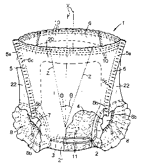
Fig. 1 is a perspective view showing a disposable pull-on
diaper 1 as viewed from the side of a front waist region 20 and
partially broken away, Fig. 2 is an exploded plan view of the
diaper 1 shown by Fig. 1 as before the diaper 1 is shaped into
pants and Fig. 3 is a sectional view taken along a line A - A
in Fig. 2.
The diaper 1 basically comprises a liquid-pervious
topsheet 2, a liquid-impervious backsheet 3 and a liquid-
absorbent panel 4 disposed between the top- and backsheets 2,
3. The liquid-absorbent panel 4 has its entire surface covered
with and bonded to liquid-pervious tissue paper (not shown) and
this panel 4 is bonded to inner surface of at least one of the
top- and backsheets 2, 3 via the tissue: paper.
As seen in Fig. 2, the diaper 1 is longitudinally composed
of a front waist region 20, a rear waist region 22 and a crotch
CA 02352703 2001-07-09
2000-218509
-5-
region 21 extending between said front and rear waist regions
20, 22. The diaper 1 is contoured by transversely opposite side
edge portions la, lb, lc extending in longitudinal direction
of the diaper 1 and longitudinally opposite end portions ld,
le extending in transverse direction of the diaper 1. The side
edge portions lc in the crotch region f.1 curve transversely
inward so as to describe circular arcs . The side edge portions
la, lb, lc are respective provided with leak-barrier cuffs 8
each extending in the longitudinal direction of the diaper 1.
In the diaper 1 , the end portions l~d, le of the front and
rear waist regions 20, 22, respectively, are dimensioned to be
substantially equal to each other. The t=ransversely opposite
side edge portions la of the front waist region 20 extend from
the end portion ld toward the crotch region 21 so that these
side edge portions la get nearer to a longitudinal center line
X bisecting a dimension defined between the transversely
opposite edge portions la, lb, lc. On the contrary, the
transversely opposite side edge portions lb of the rear waist
region 22 extend from the end portion le toward the crotch region
21 so that these side edge portions lb get away from the
longitudinal center line X.
To shape the diaper 1 from its state shown by Fig. 2 into
the desired pull-on undergarment, the diaper 1 is folded with
CA 02352703 2001-07-09
2000-218509
-6-
its inner surface inside along a transverse center line Y
bisecting a dimension defined between the longitudinally
opposite end portions lc, ld of the diaper 1. Then the
transversely opposite side edge portions la, lb of the front
and rear waist regions 20, 22, respectively, are put flat and
bonded together. In the diaper 1 having been pants-shaped, a
waist-hole 6 opens upward as viewed in Fig. l, a pair of leg-holes
7 open right- and leftward, respectively, also as viewed in Fig.
1, respectively, and a pair of bonding zones 5 extend along the
transversely opposite side edge portions la, lb of the front
and rear waist regions 20, 22.
Each of the bonding zones 5 comprises an upper end section
5a extending adjacent the waist-hole 6 and a lower end section
5b extending adjacent the associated leg-hole 7. The bonding
zone 5 extend from the upper section 5a toward the lower end
section 5b so that the bonding zone 5 get nearer to and obliquely
of the longitudinal center line X.
Two-dotted chain lines Z in Fig. 1 indicate imaginary
positions of the bonding zones 5 on the' assumption that the
bonding zones 5 have been translated toward the longitudinal
center line X and intersected the longitudinal center line X
preferably at an angle 8 of 5 -- 30° , respectively.
With the diaper 1 put on a wearer' s body, the upper end
CA 02352703 2001-07-09
2000-218509
portions 5a of the respective bonding zones 5 lie at
transversely lateral sides of the wearer and the lower end
portions 5b of the respective bonding zones 5 lie on the belly
of the wearer. Each of the bonding zones 5 comprises a plurality
of heat-sealed lines 5c intermittently arranged in the
longitudinal direction of the diaper 1.
Each of the cuffs 8 basically comprises a fixed side edge
portion 8a fixed to the topsheet 2, a free side edge portion
8b opposed to the fixed side edge portion 8a and extending in
the longitudinal direction and longitudinal opposite end
portions 8c collapsed inward transversely of the diaper 1 and
bonded to the topsheet 2 in such collapsed state. In the rear
waist region 22, the fixed side edge port~'_on 8a further extends
transversely outward to define an outer extension 8d. A
longitudinally extending elastically stretchable member 9 is
bonded under tension to the free side edge portion 8b of the
cuff 8 in a manner that the elastically stretchable member 9
is wrapped by a part of the free side edge portion 8b. The cuff
8 is normally biased by the elastically stretchable member 9
to rise from the topsheet 2.
Elastic member 10 comprising a plurality of elastic
elements which are circumferentially stretchable is bonded
under tension to peripheral edge of the waist-hole 6. Portions
CA 02352703 2001-07-09
2000-218509
_8_
of the elastic member 10 lying on the tran:>versely opposite side
edge portions la of the diaper 1 are disposed between the
transversely opposite side edge portions 3a of the backsheet
3 and the outer extensions 8d of the respective cuffs 8 and bonded
to at least one of these portions 3a, 8d. Remaining portions
are disposed between the top- and backslheets 2, 3 and bonded
to at least one of these sheets 2, 3.
An elastic member 11 comprising a plurality of elastic
elements which are circumferentially stretchable is bonded
under tension to each of the leg-holes 7 .along peripheral edge
thereof. The elastic member 11 associai~ed with the leg-hole
7 actually consists of a first elastic member lla and a second
elastic member llb. These first and second elastic members lla,
llb respectively have sections llal, llbl extending
transversely across substantially middle zone of the crotch
region 21, on one hand, and sections 11a2,, llbz extending along
the transversely opposite side edge portions lc of the diaper
1 in the crotch region 21. The respective sections llal, llbl
of these first and second elastic members 11a, llb are disposed
between the backsheet 3 and the panel 4 and bonded to the
backsheet 3 while the respective sections 11a2, 11b2 of these
first and second elastic members lla, llb are disposed between
and bonded to the transversely opposite side edge portions 3a
CA 02352703 2001-07-09
2000-218509
_9_
of the backsheet 3 and the outer extension 8d of the cuff 8.
Referring to Fig. 1, a plurality of gathers are formed
along the peripheral edge of the waist-hole 6, the peripheral
edges of the leg-holes 7 and the free side edge portions 8b of
the cuffs 8 and the free side edge port:i.ons 8b rise from the
topsheet 2 as the respective elastic members 9, 10, 11 contract.
Along the transversely opposite side edge portions la,
lb, lc of the diaper 1, the transversely opposite side edge
portions 2a of the topsheet 2 transversely extend outward
slightly beyond the transversely opposite side edges of the
panel 4 and the transversely opposite side edge portions 3a of
the backsheet 3 as well as the outer extensions 8d of the cuffs
8 further extend transversely outward beyond the transversely
opposite side edge portions 2a of the topsheet 2. The
transversely opposite side edge portions 2a are disposed
between the transversely opposite side edge portions 3a and the
outer extensions 8d and banded to at le<~st one of them. The
side edge portions 3a and the outer extensions 8d are put flat
and bonded together. Along the longitudinally opposite end
portions ld, le, portions of the top- and backsheets 2, 3
extending transversely outward beyond longitudinally opposite
ends of the panel 4 are put flat and bonded together.
Fig. 4 illustrates a manner in which. the diaper 1 is taken
CA 02352703 2001-07-09
2000-218509
-10-
off from the wearer's body lying on the back. As illustrated,
the helper may grasp the end portion ld of the diaper 1 with
his or her left hand and the end portion le of the diaper 1 with
his or her right hand. To take the diaper 1 from the wearer's
body, the side edge portions la or the ;side edge portions lb
may be torn open from the waist-hole 6 toward the leg-holes 7
by pulling the left hand grasping the end portion ld in the front
waist region 20 toward the helper' s own left flank with the end
portion le in the rear waist region 22 held by the right hand.
Then, with the end portion le held by the left hand, the other
side edge portions lb or la may be torn open from the waist-hale
6 toward the leg-holes 7 by pulling the r3_ght hand grasping the
end portion ld in the front waist region 20 toward the helper's
own right flank.
A direction in which a force is exerted on the diaper 1
to tear open this is substantially coincident with the direction
in which the respective bonding zones 5. Consequently, the
diaper 1 can be smoothly torn open along the respective bonding
zones 5 without an anxiety that the force might be exerted on
any other zones than the bonding zones 5. According to this
diaper 1, the angle 8 at which the respective bonding zones
5 intersect the longitudinal center line :K may be varied within
a range of 5 - 30° to adjust a slant of the zones 5 with respect
CA 02352703 2001-07-09
2000-218509
-11-
to the longitudinal center line X.
Fig. 5 is a perspective view showing an alternative
embodiment of the disposable diaper 1 according to this
invention as viewed from the side of the front waist region 20
and Fig. 6 is an exploded plan view showing the diaper 1 of Fig.
5 as before the diaper 1 is pants-shaped. The diaper 1 of Fig.
5 basically comprises the similar members to those constituting
the diaper 1 of Fig. 1 and no description in detail is given
hereunder.
According to this embodiment, theitransversely opposite
side edge portions la in the front waist. region 20 as well as
the transversely opposite side edge portions lb in the rear
waist regions 22 extend in parallel to each other and an
auxiliary elastic member 12 comprising a plurality of elastic
1~ elements is bonded under tension to the dp_aper 1 so as to extend
transversely across the front waist region 20 between the
elastic member 10 associated with the waist-hole and the elastic
members 11 associated with the respective leg-holes. The
auxiliary elastic member 12 has its stretch stress gradually
increasing from its element 12a lying most adjacent the elastic
member 10 associated with the waist-hole t-oward its element 12d
lying most adjacent the elastic members 11 associated with the
leg-holes.
CA 02352703 2001-07-09
2000-218509
- 12-
As will be apparent from Fig. 6, th<~ waist-hole 6 opening
upward as viewed in Fig. 5 and the pair of leg-holes 7 opening
left- and rightward also as viewed in Fig. 5 are defined as the
front and rear waist regions 20, 22 are :bonded together along
b their transversely opposite side edge portions la, lb of the
front and rear waist regions 20, 22.
With the diaper 1 according ito this embodiment,
contraction of the respective elements 12a - 12d constituting
the auxiliary elastic member 12 causes an upper zone of the rear
waist region 22 to be slightly drawn near 'toward the front waist
region 20 and causes a lower zone of the rear waist region 22
to be drawn nearer to the front waist region 20 than the upper
zone. The respective bonding zones 5 extending along the
transversely opposite side edge portions la, lb of the front
and rear waist regions 20, 22 from upper ends 5a toward lower
ends 5b thereof so that these bonding zones 5 get nearer to the
longitudinal center line X. With the diaper 1 put on the
wearer' s body, the upper ends 5a of the respective bonding zones
5 lie on transversely opposite flanks of the wearer and the lower
ends 5b of the respective bonding zones 5 lie on the wearer' s
belly.
An alternative arrangement is also possible according to
which the respective bonding zones 5 extend from the upper ends
CA 02352703 2001-07-09
2000-218509
-I3-
5a toward the lower ends 5b getting nearer to the longitudinal
center line X so that the lower ends 5b myy lie on the wearer' s
hip. Such arrangement will be convenient when the diaper 1 is
taken off from the wearer lying on his or her face.
The topsheet 2 may be formed with a liquid-pervious sheet
such as a nonwoven fabric or a porou:~ plastic film, more
preferably by a liquid-pervious and hydrophilic sheet. The
backsheet 3 may be formed with a hydrophobic nonwoven fabric,
a liquid-impervious plastic film or a laminated sheet
consisting of a hydrophobic nonwoven fabric and a plastic film,
more preferably with a breathable and liquid-impervious sheet.
It is also possible to form the backsheet 3 with a composite
nonwoven fabric (SMS nonwoven fabric) comprising highly
water-resistant and a flexible melt blown nonwoven fabric and
two layers of spun bond nonwoven fabric sandwiching
therebetween the opposite sheet surfaces of the melt blown
nonwoven fabric.
The nonwoven fabric used for this invention may be of
various types such as spun lace-, needle punch-, melt blown-,
0 thermal bond-, spun bond- , chemical bond- and airthrough- types .
The component fiber of the nonwoven fabric. may be selected from
a group including polyolefine-, polyester- and polyamide-based
fibers and core-sheath-, eccentric core-sheath- and
CA 02352703 2001-07-09
2000-218509
-14-
separated-type polyethylene/polypropylene or polyester
conjugated fibers.
The elastic members 9, 10, 11, 12 may comprise thread-,
filament-, film- or ribbon-like elastomer of natural or
synthetic rubber.
The panel 4 comprises a mixture of fluff pulp, high
absorption polymer particles and thermoplastic synthetic resin
fiber compressed to a desired thickness. The high absorption
polymer may be selected from a group including graft polymer
of starch-based, modified cellulose-based and synthetic
polymers.
Bonding the top- and backsheets 2, 3 to each other or to
the cuffs 8, bonding of the panel 4 and attaching of the elastic
members 9, 10, 11 may be carried out by means of suitable adhesive
such as a hot melt adhesive or a pressure-sensitive adhesive,
or using suitable welding technique such as heat sealing or
supersonic sealing technique. Use of the hot melt adhesive is
particularly preferable as the adhesive means.
This invention is not limited to the disposable pull-
on diaper but applicable also to the other disposable pull-
on undergarments such as training pants or incontinent pants.
In the disposable pull-on undergarment according to this
invention, the respective bonding zones extend from the upper
CA 02352703 2001-07-09
2000-218509
-15-
ends toward the lower ends thereof, getting nearer to the
longitudinal center line so that the lower ends may lie on the
wearer's belly or hip. When the diaper is taken off from the
wearer lying on his or her back or on his or her face, the
direction in which the force is exerted on the diaper to tear
open this is substantially coincident with the direction in
which each of the bonding zones extends and therefore
substantially no force is exerted on any other zones than the
bonding zones . As a result, the diaper can. be smoothly torn open
along the respective bonding zones.