Note: Descriptions are shown in the official language in which they were submitted.
CA 02352928 2001-07-11
1
BELT-MOUNTED VACUUM APPARATUS AND METHODS
TECHNICAL FIELD
The present invention relates to portable vacuum apparatus and
methods, and more specifically, to belt-mounted vacuums.
BACKGROUND OF THE INVENTION
Portable vacuums that may be carried or worn by an operator have
great utility in a variety of applications. For example, portable vacuums are
often
used in commercial settings for cleaning densely congested areas, such as
office
areas, hotels, theaters, and restaurants. They may also be used around the
home
for cleaning stairways, automobiles, or other living areas. A variety of
portable
vacuum styles are known, including "back pack" vacuums, shoulder-mounted
vacuums, and belt-mounted vacuums.
Figure 1 is an isometric view of a conventional belt-mounted
vacuum 20. The belt-mounted vacuum 20 includes a housing 22 attached to a
carrier belt 24. The housing 22 has a vacuum unit chamber 25 that typically
includes a fan driven by an electric motor (not shown). The housing 22 also
includes a bag chamber 26 that typically contains an inner bag (not shown) for
receiving dust, dirt, and particulate matter. A vacuum hose 28 is coupled to
an
intake port 30 disposed in an openable cover 32 that leads to the bag chamber
26.
An exhaust port 31 is disposed in the housing 22 and leads to the vacuum unit
chamber 24.
In operation, the carrier belt 24 is fastened around the operator's
waist with the housing 22 positioned along the operator's back. The housing 22
may have a bent or contoured shape to conform, to the operator's body. The
electric motor drives the fan which in turn drives air through the exhaust
port 31
and creates suction within the bag charnber 26 and the vacuum hose 28. A flow
of air is thereby drawn through the vacuum hose 28 and through the intake port
30, drawing dust, dirt, and particulates from the surface being cleaned into
the
CA 02352928 2001-07-11
2
bag chamber 26. The particle-laden airflow may t:hen pass through the inner
bag
which filters and collects the dust and particulates from the airstream for
later
disposal. The resulting clean airstream passes through the fan and exits
through
the exhaust port 31. Belt-mounted vacuums 20 of the type shown in Figure 1 are
disclosed, for example, in U.S. Patent No. 4,944,065 issued to Svanberg et al.
Although desirable results may be achieved using conventional
belt-mounted vacuums, some drawbacks exist. For example, the operator may
attempt to compensate for the weight of the belt-mounted vacuum 20 on the
operator's back by leaning forward into a hunched position. This may be
uncomfortable and may cause additional stress or fatigue for the operator,
especially after extended periods of use.
Also, when it is time to empty or change the inner bag, the operator
typically must remove the belt-mounted vacuum 20 in order to reach the
openable cover 32 of the bag chamber 26 in order to reach the inner bag. Thus,
the belt-mounted vacuum 20 typically must be removed (and re-donned) each
time the inner bag must be accessed. Alternately, the operator may attempt to
enlist the assistance of another person, or may even resort to awkwardly
sliding
the belt 24 around his or her waist so that the housing 22 is moved around
from
the back side of the operator to a reachable position. These alternate
approaches
may reduce the efficiency and productivity of the operator, and may decrease
the
operator's satisfaction with the device.
Another disadvantage of conventional devices is that because the
controls of the belt-mounted vacuum are typically located on or near the
vacuum
unit chamber 24, the operator may need to reach backwardly to the housing 20
in
order to turn the vacuum on or off, or to adjust the power setting. This may
be
inconvenient and may further reduce the operator's satisfaction with the
device.
SUMMARY OF THE INVENTION
The present invention is directed to belt-mounted vacuum
apparatus and methods. In one aspect, a belt-mounted vacuum apparatus
CA 02352928 2001-07-11
3
includes a belt member adapted to engage about an operator's waist, a dirt
receptacle attached to the belt member and having an intake port, and a vacuum
unit attached to the belt member and spaced apart from the dirt receptacle.
The
vacuum unit is operatively coupled with the dirt receptacle such that an
airflow
created by the vacuum unit propels particulates through the intake port and
into
the dirt receptacle. Because the vacuum unit is spaced apart from the dirt
receptacle, the vacuum apparatus may advantageously provide improved balance
and weight distribution, and may increase the operator's satisfaction with the
device. In alternate aspects, the vacuum unit may be spaced apart from the
dirt
receptacle by a small distance, or may be positioned on opposite sides of the
operator, or any other desired spacing.
In another aspect, a belt-mounted vacuum apparatus includes a belt
member having a stiffened portion. The stiffened portion may, for example,
comprise an outer shell. Alternately, the belt member may also include a
flexible, padded layer that engages with the operator's waist. The stiffened
portion may be disposed within the flexible layer. In another aspect, the belt
member may include a plurality of stiffened portions.
In yet another aspect, a belt-mounted apparatus includes a belt
member adapted to engage about the operator's waist, a dirt receptacle
attached
to the belt member and located at an accessible location on the belt member.
The
apparatus further includes a vacuum unit attached to the belt member and
operatively coupled with the dirt receptacle such that an airflow created by
the
vacuum unit propels particulates- through the intake port and into the dirt
receptacle. In alternate aspects, the dirt receptacle may be located proximate
a
front side of the operator's waist, or along a left or right side of the
operator's
waist, or at any other accessible location on the belt member. Because the
dirt
receptacle is located at an accessible location, the belt-mounted vacuum
apparatus may improve the efficiency and operability of the device.
CA 02352928 2001-07-11
4
BRIEF DESCRIPTION OF THE DRAWINGS
Figure 1 is an isometric view of a belt-mounted vacuum in
accordance with the prior art.
Figure 2 is an isometric view of a belt-mounted vacuum in
accordance with an embodiment of the invention.
Figure 3 is a side elevational view of the belt-mounted vacuum of
Figure 2.
Figure 4 is an isometric view of a dirt receptacle of the belt-
mounted vacuum of Figure 2.
Figure 5 is a side isometric view of a belt-mounted vacuum in
accordance with an alternate embodiment of the invention.
Figure 6 is a back isometric view of the belt-mounted vacuum of
Figure 5.
Figure 7 is a front isometric view of the belt-mounted vacuum of
Figure 5.
Figure 8 is a side elevational view of the belt-mounted vacuum of
Figure 5 being worn by an operator.
Figure 9 is a side elevational view of a dirt receptacle attached to a
belt member by a hinge.
Figure 10 is a side elevational view of a belt-mounted vacuum in
accordance with yet another embodiment of the invention.
DETAILED DESCRIPTION OF THE INVENTION
The present invention is generally directed to belt-mounted vacuum
apparatus and methods. Many specific details oiF certain embodiments of the
invention are set forth in the following description and in Figures 2-10 to
provide
a thorough understanding of such embodiments. One skillled in the art will
understand, however, that the present invention may have additional
CA 02352928 2001-07-11
embodiments, or that the present invention may be practiced without several of
the details described in the following description.
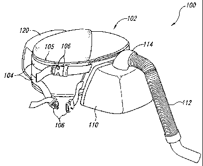
Figures 2 and 3 are isometric and elevational views, respectively,
of a belt-mounted vacuum 100 in accordance with an embodiment of the
5 invention. The belt-mounted vacuum 100 includes a belt 102 adapted to engage
about an operator's waist, a dirt receptacle 110 attached to the belt 102, and
a
vacuum unit 120 attached to the belt 102. The vacuum unit '120 consists of a
separate unit from the dirt receptacle 110, and the vacuum unit 120 and dirt
receptacle 110 are spaced apart from each other along the belt 102.
In the embodiment shown in Figure 2, the belt 102 includes a pair
of flexible straps 104 attached to an inner pad 105 that engages the
operator's
waist. Quick-disconnect couplings 106 are attached to the ends of the straps
104
which allow the belt 102 to be easily donned or removed. Alternately, the
couplings 106 may be replaced with a wide variety of suitable attachment
devices
known to those of skill in the art, including buckles, buttons, snaps, hook-
and-
loop fasteners such as those sold under the trademark VELCRO , or other
similar devices.
An intake hose 112 is attached to a swivel assembly 114 that is
fluidly coupled to an intake port 117 (Figure 4) of the dirt receptacle 110.
As
shown in Figure 3, an auxiliary hose 122 is coupled between a suction inlet
124
leading into the vacuum unit 120, and a suction outlet 126 leading out of the
dirt
receptacle 110. An exhaust vent 128 is disposed within a sidewall of the
vacuum
unit 120. A control unit 130 is electrically connected to the vacuum unit 120
by
a control line 132. The control unit 130 is tethered to the belt 104 by a
bungee
134 (Figure 3). Power may be supplied to the vacuum unit 120 by a battery unit
stowed within the vacuum unit 120, or alternately, by a power cord (not
shown).
Figure 4 is an isometric view of the dirt receptacle 110 of the belt-
mounted vacuum 100 of Figure 2. The dirt receptacle 110 is shown in Figure 4
in an open position. In this embodiment, the dirt receptacle 110 includes a
mounting portion 115 that attaches to the belt 102, and a shell member 116
CA 02352928 2001-07-11
6
hingeably attached to the mounting portion 115. The intake port 117 and the
suction outlet 126 (Figure 3) are disposed through the shell member 116. An
inner bag (or filter element) 119 may be mounted within the dirt receptacle
110
to filter and contain dirt and particulates entering the dirt receptacle 110
through
the intake port 117. A dust filter 118 covers the suction outlet 126.
The belt-mounted vacuum 100 advantageously has a vacuum unit
120 that is separate from the dirt receptacle 110. Because the vacuum unit 120
is
separate from the dirt receptacle 110, the vacuum unit 120 and dirt receptacle
110
may be spaced apart from each other along the belt 102. Thus, the belt-mounted
vacuum 100 may provide a more even distribution of the weight of the apparatus
around the operator's waist.
One may note that the vacuum unit 120 may be spaced apart from
the dirt receptacle 110 any desire distance around the circumference of the
belt
102, including on opposite sides of the operator. For example, as shown in
Figure 2, the vacuum unit 120 may be positioned approximately 180 degrees
around the circumference of the belt 102 (i.e., opposite from) the dirt
receptacle
110. In this configuration, the vacuum unit 120 may be positioned on one side
of
the operator (e.g., the operator's left side), and a dirt receptacle 110 may
be
positioned on the other side of the operator (e.g., the operator's right
side). In one
aspect, the vacuum unit 120 may be placed proximate the operator's back side,
and dirt receptacle 110 may be positioned in a convenient location proximate
the
operator's front side. Because the belt-mounted vacuum 100 having the vacuum
unit 120 spaced apart from the dirt receptacle 110 provides a more even,
balanced weight distribution on the operator's waist and hips, the operator
may be
less likely to suffer from stress or fatigue. Also, the operator is less
likely to
hunch over to compensate for the weight of the belt-mounted vacuum 100,
thereby improving the operator's satisfaction witli the device. Desirable
results
may be achieved by having the vacuum unit 120 spaced apart from the dirt
receptacle 110 along the belt 102 by even a small. distance (e.g., a few
inches or
less).
CA 02352928 2001-07-11
7
Another advantage of the belt-mounted vacuum 100 is that the dirt
receptacle 110 may be conveniently positioned within the operator's reach so
that
the operator may change the inner bag 119 or the filter element 118 without
removing the belt-mounted vacuum 100. This aspect allows the operator to
quickly and efficiently change the inner bag 119 c-r the filter element 118
without
a time-consuming disruption to the operator's work schedule. The dirt
receptacle
110 may, for example, be positioned anywhere along the front side of the
operator so that the operator is not required to reach backwardly or twist
around
excessively in order to access the dirt receptacle; 110. The dirt receptacle
110
need not be positioned at the center of the front side of the operator, but
may be
positioned at any accessible, conveniently-reachable location. For example, in
alternate embodiments, the dirt receptacle 110 may be positioned anywhere
along
the front side of the operator, or along either the left or right side of the
operator,
or even slightly toward the back side of the opei-ator. Thus, the dirt
receptacle
110 may be positioned at a variety of accessible locations on the belt 102,
wherein an accessible location is defmed as a location that the operator may
reach without removing the belt-mounted vacuurn 100, and without the necessity
of sliding the belt 102 around the operator's waist.
Yet another advantage of the belt-niounted vacuum 100 is that the
control unit 130 is remotely connected to the vacuium unit 120 by the control
line
132. Because the control unit 130 is removed iErom the vacuum unit 120, the
operator may controllably adjust the vacuum unit 120 easily and efficiently
with
the vacuum unit 120 positioned anywhere along the belt 102. For example, with
the vacuum unit 120 positioned along the operatc-r's back side, the operator
may
actuate the control unit 130 to control the suction power of the vacuum unit
120,
or to turn the vacuum unit 120 on or off, without reaching around or turning
excessively in order to access the vacuum unit 120, and without removing the
belt-mounted vacuum 100. Again, time-consumine, interruptions of the
operator's work schedule may be further reduced or eliminated.
- -----------
CA 02352928 2001-07-11
8
Figure 5 is a side isometric view of' a belt-mounted vacuum 200 in
accordance with an alternate embodiment of the invention. Figures 6 and 7 are
back and front isometric views, respectively, of the belt-mounted vacuum 200
of
Figure 5. The belt-mounted vacuum 200 includes a belt member 202 having an
outer, stiffened layer 203 and an inner flexible (or padded) layer 204.
Flexible
straps 207 are attached to the stiffened layer 203 by rivets 205 (Figure 7),
and
connectors 206 are attached to the ends of the flexible straps 207 to allow
the belt
member 202 to be fastened around an operator's waist.
The belt-mounted vacuum 200 further includes a dirt receptacle
210 and a vacuum unit 220. The dirt receptacle 210 and the vacuum unit 220 are
attached to the belt member 202 and are spaced apart from each other around
the
circumference of the belt member 202. As the shown in Figure 6, with the
connectors 206 centered along the front side of the operator, the vacuum unit
220
is centered along the back side of the operator, and a dirt receptacle 210 is
located along the operator's front side at a position slightly offset to the
operator's
right side.
The dirt receptacle 210 includes a removable top portion 212
coupled to a container portion 214 by clips 215. An intake duct 216 is
swivelably (or rotatably) coupled to an intake aperture 217 (not shown)
disposed
in the top portion 212. A suction outlet 218 is disposed in the container
portion
214.
The vacuum unit 220 includes a housing 222 having an electric
motor that drives a suction fan (not shown). An exhaust vent 224 (partially
shown in Figure 6) is disposed in one end of the housing 222. A suction inlet
226 is also disposed in the housing 222. A suction duct (or conduit) 228 is
fluidly coupled between the suction inlet 226 of the vacuum unit 220 and the
suction outlet 218 of the dirt receptacle 210. A shield 230 is disposed about
the
casing 222 of the vacuum unit 220 to protect the casiLig 222 from blows that
might otherwise damage the vacuum unit's suction fan or motor. A carrying
handle 232 is disposed in the shield 230. A power cord 234 is connected to the
CA 02352928 2001-07-11
9
casing 222 to provide power to the electric motor.. In alternate embodiments,
the
power cord 234 may be eliminated, and the vacuum unit 220 may be battery-
powered. A control cable 236 is coupled between the casing 222 and the dirt
receptacle 210. A control switch 238 (Figure 7) is located on the container
portion 214 of the dirt receptacle 210 for adjustably controlling the vacuum
unit
220.
Figure 8 is a side elevational view of the belt-mounted vacuum 200
of Figure 5 being worn by an operator. As shown in Figure 8, the belt member
202 may be fastened around the operator's waist with the dirt receptacle 210
positioned along the front side of the operator, and the vacuum unit 220
centered
along the operator's back side. A vacuum hose 240 may be coupled to the intake
duct 216 and to a vacuum attachment 242 for cleaning a surface (e.g. a floor).
As shown in Figure 8, the dirt receptacle 210 may be positioned
over a portion of the operator's right (or left) leg, or may cover one of the
pockets
of the operator's clothing. To provide improved access or improved freedom of
movement, the dirt receptacle 210 may be pivotably or hingeably attached to
the
belt member 202. Figure 9 is a side elevational view of the dirt receptacle
210
attached to the belt member 202 by a hinge 260. The hinge 260 allows the dirt
receptacle 210 to pivot back and forth as indicated by arrow 262 as the
operator
moves or walks, or to allow the operator to access his or her pocket. Of
course,
the vacuum unit 220 may also be pivotably or hingeably attached to the belt
member 202.
The belt-mounted vacuum 200 may advantageously provide the
desirable features described above, and may also provide improved comfort and
convenience for the operator. Because the belt member 202 includes an outer
stiffened layer 203, the belt-mounted vacuum 200 may more evenly distribute
the
weight of the vacuum unit 220 and the dirt receptacle 210 on the operator's
waist
and hips. This may advantageously improve the comfort of the belt member 202
in comparison with flexible belts, thereby improving the operator's
satisfaction
with the device and allowing the operator to opei-ate the device comfortably
for
CA 02352928 2001-07-11
extended periods. Also, because the stiffened layer 203 is relatively stiff,
the
ease of handling and storage of the belt-mounted vacuum 200 may be improved
compared with belt-mounted vacuums having entirely flexible belts.
The stiffened layer 203 may be fabricated from a variety of
5 materials, including plastic, leather, fiberglass, or other suitable
materials.
Although the stiffened layer 203 is shown as forming an outer surface of the
belt
member 202, it should be understood that the stiffened layer 203 may be
disposed within the flexible layer 204. In an alternate aspect, the flexible
layer
204 may be eliminated, and the belt member 202 may consist solely of the
10 stiffened (or "shell") layer 203. Furthermore, the stiffened layer 203 need
not be
a unitary piece, but rather, may be segmented. For example, as shown in Figure
7, the stiffened layer 203 may be divided along dividing line 250, resulting
in two
segments of the stiffened layer 203. The resulting segments may, for example,
be joined by the vacuum unit 220, the flexible layer 204, or by other suitable
means. Alternate, multi-segmented embodiments are also readily conceivable.
Another advantage of the belt-mounted vacuum 200 is that the
inner flexible layer 204 may absorb vibration and heat emanating from the
motor
of the vacuum unit 220, thereby improving the operator's comfort and
satisfaction with the device. Preferably, the inner flexible layer 204 is a
resilient,
compressible layer that conforms to the shape of the operator's body. The
flexible layer 204 may, of course, be composed of a variety of materials,
including rubber, nylon, foam, synthetic or natural fibers, or other suitable
materials.
Figure 10 is a side elevational view of a belt-mounted vacuum 300
in accordance with yet another embodiment of the invention. In this
embodiment, the belt-mounted vacuum 300 includes a dirt receptacle 310
attached to a belt 302, and a vacuum unit 320 attached to the belt 302 and
spaced
apart from the dirt receptacle 310. An intake hose 312 h4ving an open end 313
is
coupled to an inlet port 314 of the vacuum unit 320. _ A dirty-air conduit 316
is
coupled between an outlet port 318 of the vacuurri unit 320, and a dirty-air
inlet
CA 02352928 2001-07-11
11
322 of the dirt receptacle 310. An exhaust port 324 is disposed in the dirt
receptacle 310. The belt 302 includes connectors 303 for clasping the ends of
the
belt 302 together about an operator's waist. A control switch 330 is
positioned on
the vacuum unit 320, and a power cord 332 provides power to the vacuum unit
320.
In operation, the operator puts on the belt-mounted vacuum 300
and positions the open end 313 of the intake hose 312 proximate a surface to
be
cleaned. The vacuum unit 320 creates a suction airflow that draws dirt, dust,
and
particulates into the open end 313 and through the; intake hose 312. The
particle-
laden airstream enters the inlet port 314, passes through the vacuum unit 320,
and
exits through the outlet port 318. The particle-laden airstream continues
through
the dirty-air conduit 316 and enters the dirty-air inlet 322 of the dirt
receptacle
310. The particle-laden airstream may then pass through a filter, such as a
conventional vacuum bag, which filters the dirt, dust, and particulates from
the
particle-laden airstream. A resulting clean airstream exits the dirt
receptacle 310
through the exhaust port 324.
An advantage of the belt-mounted vacuum 300 is that the vacuum
unit 320 is positioned between the dirt receptacle 310 and the intake hose
312.
This configuration may provide improved suction efficiency at the opening 313
of the .intake hose 312 compared with alternate embodiments described above.
Thus, the greater suction force may be obtained at the opening 313.
Alternately,
the smaller, more lightweight vacuum unit 320 may be used. Because the
vacuum unit 320 is spaced apart from the dirt receptacle 310 along the belt
302,
the above described advantages of improved weight distribution, balance, and
ease and satisfaction of use may be achieved.
It should be noted that the belt-mounted vacuum 300 (like the
previously described embodiments) may be positioned on the operator's waist in
a wide variety of orientations, including with either the.vacuum unit 320 or
the
dirt receptacle 310 located along the operator's fi-ont side, and the other of
the
vacuum unit 320 or the dirt receptacle 3101ocated along the operator's back
side.
CA 02352928 2001-07-11
12
Alternately, the vacuum unit 320 and the dirt receptacle 310 may be positioned
on opposing lateral sides of the operator. The vacuum unit 320 need not be
positioned on an opposite side of the operator from the dirt receptacle 310.
As
stated above, having the vacuum unit 320 spaced apart from the dirt receptacle
310 along the belt 302 by'even a small distance (e.g., a few inches or less)
may
improve the weight distribution and balance of the belt-mounted vacuum 300 in
comparison with conventional devices.
The detailed descriptions of the above embodiments are not
exhaustive descriptions of all embodiments contemplated by the inventors to be
within the scope of the invention. Indeed, persons skilled in the art will
recognize that certain elements of the above-described embodiments may
variously be combined or eliminated to create further embodiments, and such
further embodiments fall within the scope and teachings of the invention. It
will
also be apparent to those of ordinary skill in the art that the above-
described
embodiments may be combined in whole or in part to create additional
embodiments within the scope and teachings of the invention.
Thus, although specific embodiments of, and examples for, the
invention are described herein for illustrative purposes, various equivalent
modifications are possible within the scope of the invention, as those skilled
in
the relevant art will recognize. The teachings provided herein can be applied
to
other belt-mounted vacuum apparatus and methods, and not just to the
embodiments described above and shown ini the accompanying figures.
Accordingly, the scope of the invention should be detennined from the
following
claims.