Note: Descriptions are shown in the official language in which they were submitted.
CA 02353288 2002-07-02
SKIN OF AN AIRPhANE DOOR
The invention relates to the skin of an airplane door,
which conforms to the surrounding surface contour of the
fuselage, which is connected with a door frame, which door
frame has supports arranged in the longitudinal direction of
the fuselage and spaced with respect to one another in the
circumferential direction, and which during the flight is
exposed to a pressure load direction.
In the closed position; the skin of an airplane door
conforms to the surface contour of the fuselage whzch
surrounds it. The skin cor-responds,to the outer wall of the
door. It essentially has a constant material thickness and
seals off the door opening in the closed position and,
without any transition, conforms to the surface contour of
the fuselage. It is therefore uniformly curved in the
circumferential direction and has no elevations or
indentations. Recessed grips are covered.
2
CA 02353288 2001-09-20
The normal form of the skin of an airplane door
corresponds to the original form of the skin, as
manufactured. The skin exhibits its normal shape before and
after the landing of the airplane.
The skin of the airplane door is fastened on supports
which are arranged horizontally along the door width. The
supports are therefore aligned in the longitudinal direction
of the fuselage. These supports are spaced with respect to
one another in the circumferential direction and are fixedly
connected with the skin. Bearing elements, which rest on
stop devices of the fuselage-side frame when the door is in
the closed position, are arranged at the ends of the
supports. These bearing elements make it possible that the
supports of the door can be supported against a pressure load
direction in the frame of the fuselage, and they prevent
that, in the closed position, the door can change its
position in the radial direction. The skin of the airplane
door forms a portion of the outer surface of the airplane.
On the door side toward the airplane cabin, the supports are
covered with a planking.
3
CA 02353288 2001-09-20
The skin forms a so-called bearing area which has to
absorb and transmit pressure loads and aerodynamic loads,
while the inside planking is part of the so-called non-
bearing area because a considerably lower stressing takes
place there than on the skin.
After the start of the airplane, the pressure
relationships between the airplane cabin and the outer
atmosphere of the airplane change increasingly. While,
inside the cabin, the pressure corresponds essentially to a
known normal atmospheric pressure, the outside pressure will
fall as the lift increases. This pressure difference between
the airplane cabin and the atmospheric environment of the
airplane results in an increasing pressure load upon the
airplane door. This is increased by aerodynamic loads by
atmospheric oncoming flows and whirls.
These pressure loads are absorbed by th.e door structure,
are transmitted to the frame of the door and are transmitted
from there, by way of the coupling of the bearing element and
the stop element, onto the fuselage structure of the
airplane.
4
CA 02353288 2001-09-20
Particularly the pressure load sucks the skin of the
airplane door out of the fuselage position radially to the
outside. The pressure loads applied to the door act in the
direction of the pressure gradient, thus from the fuselage
interior essentially in the direction toward the outside of
the fuselage. Because of the elasticity of the bearing
elements as well as of the stop devices, a very slight
displacement of the entire door takes place in the radial
direction.
However, there is also a displacement, that is, an
arching-out, of the skin of the airplane door in the
direction of the pressure drop. According to the existing
regulations, such displacements on the skin of an airplane
door may maximally have a defined value with respect to the
normal shape of the skin.
Although they are relatively slight, these
displacements, that is, archings, cause swirls which
disadvantageously influence the flow resistance. This
influences the fuel consumption of the airplane in a
measurable manner.
CA 02353288 2002-07-02
This demand for slight reliable displacements on the
skin is met in that the door receives a sufficient
stiffness. This is achieved by the supports and in that
the skin of the airplane door is dimensioned
correspondingly thick and the door is disposed in a
separate bearing with respect to the frame. This high
stiffness of the door has the disadvantage that a light-
weight construction of the previous door is not possible.
In this case, the skin causes approximately 250 of the
entire door weight.
It is an object of the invention to clearly reduce the
dimension of the skin of an airplane door with a view to a
light construction and in the process, if possible, avoid
displacements on the skin.
The present invention provides skin of an airplane
door, which conforms to the surrounding surface contour of
the fuselage, which is connected with a door frame, which
door frame has supports arranged in the longitudinal
direction of the fuselage and spaced with respect to one
another in the circumferential direction, and which during
the flight is exposed to a pressure load direction, wherein
a skin preformed against the pressure load direction is
connected with supports of the door frame.
At cruising altitude, a pressure load to the skin
takes place which has the result that the skin fits
fluidically advantageously into the surface contour of the
fuselage surrounding it. The resulting displacements are
compensated by the preformed skin and cannot
disadvantageously influence the flow resistance of
6
CA 02353288 2001-09-20
the skin. This leads to measurable savings of fuel during
the flight. By means of the invention, it is possible with
respect to a material to construct the skin in a smaller
thickness than in the case of known doors; disturbing
displacements on the skin would nevertheless essentially be
avoided. The invention thus permits a reduction of weight.
By means of less material for the skin, clearly better
characteristics of the door are achieved while the
manufacturing expenditures are essentially the same.
According to an embodiment of the invention, it is
advantageous to arch the skin in a center area along the
longitudinal axis in an essentially concave fashion and to
form an edge which is arched in the direction of the interior
of the fuselage. Qualitatively, the profile of a preforming
along the door width corresponds essentially to the indicated
course of the curve V~(b). The point-focally different
values of a preforming are a function of the material of the
thickness of the skin and also of the geometry of the door.
In the case of a door cast in one piece, it is expedient
to mill the preformed surface contour on the exterior side of
the skin. In the case of a skin produced from a fiber
7
CA 02353288 2005-07-05
composite, the preformed surface contour is achieved by means
of the lamination.
In the following, the invention will be explained in
detail by means of an embodiment and the pertaining drawings.
Figure 1 is a schematic view of the structure of an
airplane door:
Figure 2 is a view of the profile of the displacements
on one skin along the width of an airplane door at flight
altitude:
Figure 3 is a view of the preforming of a skin of the
airplane door before the start:
Figure 4 is a view of an example of a preformed skin
Figure 5 is a sectional view A--A from Figure 4, shown
in a condition on an airplane on the ground; and
Figure 5A is a sectional view similar to Figure 5,
shown in a condition on an airplane at a high in-air
cruising altitude.
8
CA 02353288 2005-07-05
Figure 1 is a schematic view of the structure of an
airplane door l, particularly the skin 2 and the door frame 3
fastened with the skin 2. The skin 2 is arched in the
circumferential direction UR corresponding to the surface
8a
CA 02353288 2001-09-20
contour of the airplane fuselage (not shown). In the case of
a passenger door, for example, the frame 3 is formed of
supports 40, 41, 42, 43, 44 which are aligned in the
longitudinal direction of the fuselage. The supports extend
approximately along the width of the door, a small edge R of
the skin 2 existing which extends along the circumference.
The supports are mutually spaced in the circumferential
direction UR. The ends of the supports are bounded by means
of a rib 5, 6. Wherever a support is in contact with a rib,
a bearing element (not shown) is arranged as a rule. Such
bearing elements are known in the prior art and described
there.
The skin has a constant material thickness and is
essentially symmetrically constructed with respect to its
longitudinal axis AT.
With the reaching of the flight altitude, the airplane
door is exposed to the pressure loads for the duration of the
cruising flight. It was found that the displacements on the
skin of the door differ within a permissible limit value.
The displacements occur permanently when the airplane has
taken off and reach their maximum when the cruising altitude
has been reached.
9
CA 02353288 2001-09-20
Figure 2 shows such displacements, as they occur at
flight altitude (approximately 11,000 m) in the case of known
doors which have a correspondingly large thickness of the
skin and therefore achieve the required stiffness of the
skin, so that the limit value of the displacement on the skin
cannot be reached.
When the displacements are considered i.n a horizontal
plane along the width of the door but this plane is in each
case vertically offset in a spaced manner along the height of
the door, sites of highest permissible displacements will
occur as well as sites of a lowest displacement. Curve V(b)
shows an average value of the permissible displacements of a
door in the system of coordinates. The width b of the door
is indicated as the abscissa. The width of the door
essentially also corresponds to the width of the skin and is
defined by the length of the distance between points bl and
b2. Since the skin is designed to be essentially symmetrical
with respect to its longitudinal axis AT, the origin of the
coordinates was for practical reasons placed in the
longitudinal axis AT. The ordinate indicates the
displacements V of the skin with respect to the normal shape
of the skin and thus with respect to the source position of
l0
CA 02353288 2001-09-20
the skin. The source position is illustrated by the abscissa
at Vo = 0. According known prior art, the source position of
the normal shape of the skin corresponds to a condition
exhibited at the known normal pressure of the atmosphere.
However, at cruising altitude, the displacement position,
instead of the source position Vo, becomes the applicable
viewing basis. The curve V(b) is not true to scale and
supplies only qualitative information in this respect.
The curve V(b) shows that, because of an elasticity of
the bearing elements as well as of the stop devices, the
entire door is displaced very slightly radially out of its
source position V~ into a new position, a displacement
position V1. When now, starting from the displacement
position V1, the displacements V of the skin along the width
b of the door are considered, it is found that a relatively
large displacement occurs at the door edge, for example bl,
which rapidly decreases in the direction of the bearing
element. No displacement exists where the bearing element is
connected with the door, that is, with the support (bll). The
displacement increases from there further into the direction
of the door center (that is, in the direction of the
longitudinal axis AT) and may reach its maximally permissible
value.
11
CA 02353288 2001-09-20
The displacement decreases further in the direction of
the other edge and also can hardly be found there on the
bearing element (b21) on the other side, in order to then
rapidly increase again in the direction of the other edge,
for example, b2.
In the case of the known doors, the material thickness
of the skin is selected such that the stiffness of the skin
is always ensured and material tensions produce only
maximally permissible displacements. In order to reduce
these displacements, the invention suggests to bring the
normal shape of the skin known from the prior art into a
preformed condition which deviates from the known normal
shape. This shape, which deviates from the known normal
shape, is called "preformed shape".
The result of a manufacturing is a door with a preformed
skin. The preformed skin does not correspond to the known
normal shape of the skin as exhibited in the source position.
The preformed skin now corresponds to an original shape
of the skin occurring on the basis of the manufacturing.
12
CA 02353288 2001-09-20
Before the take-off or after the landing, the skin is
always exhibited in the preformed shape. This preformed
shape shows deformations which deviate from the source
position and which are opposed to the deformations during the
flight, so that the deformations from the displacement
position occurring during the flight are compensated by the
predeformations produced during the manufacturing. During
the flight at cruising altitude, this results in a door which
essentially has no displacements with respect to the
surrounding surface contour of the fuselage and therefore
ideally permits no displacements from the taken-up
displacement position.
Figure 3 shows in which direction these predeformations
on the skin have to be produced during the manufacturing in
order to generate the preformed shape. The curve V"(b) shows
the profile of the skin along the door width of a shape to be
preformed.
The curve V~(b) qualitatively shows the direction of the
predeformation which is to be produced on the skin during the
manufacturing. In this case, it can be recognized that both
edges are formed toward the inside (direction of the fuselage
interior) by manufacturing, while the area where the bearing
13
CA 02353288 2001-09-20
elements are fastened to the door or the support end remains
free of deformations. This area of the support end forms the
starting basis (that is, the source position or displacement
position) for determining the quantitative magnitude of the
predeformation. Further in the direction of the door center,
the skin is also preformed to a greater degree toward the
inside in the direction of the cabin interior, that is,
against the later direction of the pressure load. By means
of the cure V~, Figure 3 shows the predeformation along the
width of the door in the profile. These predeformations
corresponding to the profile extend along the longitudinal
axis AT of the door from the top side to the bottom side of
the skin.
Figure 4 illustrates a preformed skin 20 produced by
manufacturing which is connected by means of its interior
side 21 with a door frame 30. The exterior side 22 of the
skin 20 exhibits a concave predeformation in the proximity of
the longitudinal axis AT (center area 200). In this case,
the skin 20 is further arched in the circumferential
direction UR. The edge R is arched in the direction (Z) of
the fuselage interior.
14
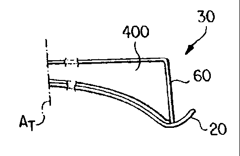
CA 02353288 2005-07-05
Figure 5 illustrates a corresponding section A-A. The
door frame 30 conforms, for example, to the contour of the
skin 20. This is demonstrated on the support 400 and the rib
60 of that figure, which are components of the door frame 30.
The support 400 and the rib 60 are, for example, riveted
together with the skin 20. However, other methods can also
be used for the connection.
Figure 5A schematically shows in solid line the
deformation of the skin 20 and frame member 400 at cruising
altitude. It should be understood that the skin (and frame
members connected therewith) elastically deform by only a
few millimeters from the position shown in Figure.5 to the
position shown in Figure 5A.
Different manufacturing-related possibilities exist for
deforming the skin.. The manufacturing-related possibility is
a function of the method of manufacturing the door. A
conventional door riveted together from individual components
offers the possibility of riveting the material of the skin
in a preformed position with respect to the supports. In
this case, the support has a recess in order to accommodate
the deformation of the skin in a form-fitting manner. No
limitations exist for fixing the preformed skin on the door
frame. There are also no restrictions with respect to the
material to be preformed.
CA 02353288 2005-07-05
In the case of a door produced by casting, which was
cast in one piece, the interior side of the skin as a rule
has the desired contour, in which case the contour of the
15a
CA 02353288 2001-09-20
skin must still be milled (on its exterior side). The
thickness of the skin must remain constant.
When the skin is manufactured from a fiber composite,
the predeformation has to be laminated correspondingly
already during the lamination of the skin.
The invention has the advantage that, during the entire
cruising time at cruising altitude, essentially no
displacements can form on the skin of the door in a
fluidically disadvantageous manner, so that the flow
resistance of the door can clearly be reduced. This leads to
measurable savings of fuel. Relative to the material, it is
possible by means of the invention to construct the skin in a
smaller thickness than in the case of known door, but
disturbing displacements on the skin are nevertheless
essentially avoided. The invention therefore permits a
reduction of weight. Clearly better characteristics of the
door are achieved by means of less material for the skin
while the manufacturing expenditures are essentially the
same.
16