Note: Descriptions are shown in the official language in which they were submitted.
CA 02353297 2001-07-19
FULLY-LOCKING TORQUE-PROPORTIONING DIFFERENTIAL
Specification
Field of the Invention
This invention relates to a torque-proportioning differential of the helical
S pinion type that includes locking means that are operable either
automatically or by
the operator of the vehicle.
Background of t_he Invention
Torque-proportioning differential of the helical gear type are well known in
the prior art, as evidenced by the prior patents to Myers No. 3,706,239,
Dissett Nos.
4,625,585, 4,365,524, 4,625,585, 4,677,876, and 4,751,853, among others.
Through
the use of this type of differential over the years, it has become apparent
that the need
exists for locking means that are operable either automatically or by the
vehicle
operator to fully lock the driven axle shafts to each other, for example, upon
the
occurrence of a spin-out condition of one of the driving wheels. This can be
achieved
by locking one side gear to the case, or by locking one axle to the case (as
is generally
done with manual locking systems).
It is also known in the shaft coupling art to provide spiral type one-way
clutches including raceway and roller means are arranged in the annular space
between a pair of concentrically spaced annular coupling members. Examples of
such coupling clutch means are presented by the Ken patent Nos. 4,341,294 and
5,638,931.
The present invention was developed to provide an improved fully-locking
torque-responsive differential that is operated between fully locked and
unlocked
conditions, respectively, either automatically or by an operator.
CA 02353297 2001-07-19
2
Summary of the Invention
Accordingly, it is a primary object of the present invention to provide a
fully-
locking torque-responsive differential including automatic or manually
operable
coupling means for locking and unlocking a given side gear to the rotary
casing of the
differential.
According to a more specific object of the invention, annular coupling means
are arranged concentrically between a tubular axially-extending hub portion of
a
given first side gear and the cylindrical wall portion of the bore of the
carrier in which
the one side gear is rotatably mounted. Non-rotatable operating means mounted
on
the differential housing within which the carrier rotates serve to operate the
coupling
means between locked engaged and unlocked disengaged conditions, respectively.
The operating means includes an operating trigger pin that is axially
displaceable
between first and second positions relative to the carrier to disengage and
engage the
coupling means, respectively. Spring means bias the trigger pin toward the
first
1 S position, whereby the coupling means are normally in the disengaged
condition.
According to the preferred embodiment of the invention, the coupling means
includes a radially-slit inner annular member that is normally biased radially
inwardly
toward an engaged condition in frictional engagement with the outer periphery
of the
hub portion of the one side gear. In this case, the trigger pin is normally
biased
axially in a direction to effect insertion of the end of the trigger pin into
a keyed
opening contained between the adjacent surfaces of the inner and outer
coupling
members, thereby to prevent relative angular displacement of the coupling
members.
The coupling rollers are in a loose condition, whereupon the inner coupling
member
rotates freely upon the associated side gear. When the trigger pin is axially
displaced
in the opposite direction to withdraw the pin from the keyed opening, the
coupling
members are relatively slightly angularly displaced to cause the rollers to
ride up their
CA 02353297 2001-07-19
3
associated coupling ramps, whereupon the split inner coupling member is
compressed
radially inwardly into locking engagement with the associated side gear,
Thereby to
lock the side gear with the housing. According to a second embodiment of the
invention, the outer coupling member is split and is resiliently biased
radially
outwardly toward frictional engagement with the wall of the bore formed in the
housing. As before, the trigger pin is biased axially into the key hole
between the
coupling members, thereby to prevent relative angular displacement of the
coupling
members from the unlocked position to the locked position.
Brief Descr~ntion of the Drawi~
Other objects and advantages of the invention will become apparent from a
study of the following specification, when viewed in the light of the
accompanying
drawings, in which:
Fig. 1 is a longitudinal sectional view of a solenoid-operated first
embodiment
of the fully torque-proportioning locking differential of the present
invention taken
along line 1-1 of Fig. 3;
Fig. 2 is a sectional view taken along line 2-2 of Fig. 1;
Figs. 3 and 4 are top plan and longitudinal sectional views, respectively, of
the housing cover member of Fig. 1;
Fig. 5 is a right-hand end view of the casing end section of Fig. 1;
Fig. 6 and 6A are sectional and detailed views, respectively, of the coupler
means of Fig. 1 when in the disengaged condition;
Figs. 7 and 7A are sectional and detailed views, respectively, of the coupler
means of Fig. 1 when in the engaged condition.
Fig. 8 is a front elevation view of the trigger ring of Fig. l, and Fig. 9 is
a
sectional view taken along line 9-9 of Fig. 8;
CA 02353297 2001-07-19
4
Figs. 10 and 1 I are front elevation and perspective views, respectively, of
the
trigger ring operating fork, and Fig. 12 is a sectional view taken along line
12-12 of
Fig. 10;
Figs. 13 and 13A are side elevation and detailed views, respectively, of the
fork operating shaft of Fig. l;
Figs. 14 and 15 are top plan and left-hand elevation views, respectively. of
the
cover block member of Fig. 1, and Fig. 16 is a sectional view taken along line
16-16
of Fig. 14.
Fig. 17 is a plan view of the retaining clip of Fig. 1, and Fig. 18 is a
sectional
view taken along line 18-18 of Fig. 17;
Fig. 19 is a sectional view of the shaft seal means of Fig. 1;
Fig. 20 is a perspective view of the position sensing switch of Fig. 1;
Fig. 21 is a longitudinal sectional view of a second embodiment of the fully-
locking torque-proportioning differential of the present invention;
Figs. 22-25 are schematic illustrations of the pneumatic, electric, hydraulic,
and cable means, respectively, for operating the coupler means of Figs. 1 and
21; and
Figs. 26 and 27 illustrate schematically a second embodiment of the coupling
means of Figs. 6 and 7 with the coupling means in the engaged and disengaged
conditions, respectively.
Detailed Descri tn ion
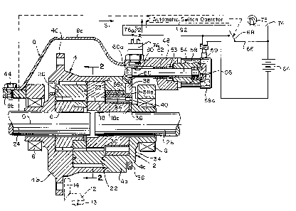
Referring first more particularly to Figs. 1-S, the fully-locking torque-
responsive differential 2 of the present invention includes a generally
cylindrical
carrier 4 that is rotatably supported by bearings 6 within the differential
housing 8 for
rotation about the axis of rotation 10. As is known in the art, the carrier 4
is sectional
and includes a cover section 4a that is bolted or welded to the carrier body
4b. The
CA 02353297 2001-07-19
carrier is rotatably driven by drive pinion 12 and ring gear 14 that is bolted
to the
flange portion 4c of the carrier body. Rotatably supported in opposite ends of
the
carrier 4 are a pair of aligned annular side gears 16 and 18. As is known in
the art,
the side gears 16 and 18 have helical teeth that enmash with corresponding
helical
S teeth on helical gears 20 and 22, respectively. The helical gears 20 and 22
are
longitudinally displaced and are in enmeshing engagement at their adjacent
ends, the
remote ends of the helical gears being connected with the associated side
gears 16 and
18. The ends of the bores containing the helical gears 20 are filled by dummy
members 23, respectively. The side gears are internally splined to the
collinearly
aligned output shafts or axles 24 and 26, respectively.
In accordance with the characterizing feature of the present invention, the
side
gear 18 includes an axially extending hub portion 18a that extends in the
opposite
direction away from the side gear 16, and the carrier end section 4a contains
an
oversized bore 30 that defines an annular space between the hub portion 18a
and the
wall surface of the bore 30. Mounted within this annular space are annular
coupling
means 34 which will be described in greater detail below in connection with
Figs. 6
and 7. The coupling mans 34 are operable between engaged and disengaged
conditions relative to the hub portion 18a of side gear 18 by operating means
including a trigger pin 36. The trigger pin 36 is carried by a radially
inwardly
directed arm portion 38a of an annular trigger member 38 that is mounted for
axial
displacement on a stepped portion 4d of the cover section 4a. The radially
inwardly
directed arm portion 38a extends within a radial slot 40 contained in the
cover section
4a as best shown in Fig. 5.
Referring to Figs. 1, 3, and 4, the differential housing 8 includes a cover
section 8a that is bolted to the main housing body 8b by bolt means 44. Welded
to
the housing cover 8a is an operating block 48 having a bushing 52 and annular
seal
CA 02353297 2001-07-19
6
means 53 (Fig. 19) that slidably receive the operating shaft 54. At its right-
hand end,
the shaft 54 includes a reduced end portion 54a that extends within chamber 56
defined by a counter bore formed in one end of cylindrical solenoid means 58,
and
a recess formed in the solenoid cover member 58a. A helical compression spring
59
is arranged in the chamber ~56 concentrically about the reduced shaft portion
54a, and
biases shaft 52 to the left in Fig. 1.
Mounted on the reduced end portion 54b at the other end of the operating
shaft 54 by the annular resilient slit retaining clip 55 (Figs. 17 and 18) is
a fork
member 60, as shown in Figs. 10-12. The fork member 60 has a first portion 60a
containing throughbore 62 that receives the reduced end portion 54b of control
shaft
54. The fork member includes a pair of spaced leg portions 60b and 60c, the
end
portions of which are provided with inwardly directed projecting portions 60d
and
60e that extend radially inwardly within circular groove 64 contained in the
outer
circumference of the trigger ring 38, as shown in Fig. 8. The retaining clip
55 is
mounted in groove 57 formed in the reduced portion 54b of operating shaft 54.
Refernng again to Fig. 1, the solenoid 58 includes a conventional helical
solenoid coil 58a that is electrically connected with the opposite poles of a
12 volt
battery 64 via a series circuit including conductor 66 containing on/off
switch 68, and
by a second conductor 70. Connected in parallel with the on/off switch 68 is a
branch
circuit conductor 74 that contains the normally open switch contact 76a of
position-
sensing switch 76, and an illuminating lamp 78. The position-sensing switch 76
is
mounted within a corresponding throughbore 78 contained in the left-hand
projecting
portion 48a of the operating block 48. Thus, the movable switch operator 80 is
positioned for engagement by the central portion 60a of the operating fork 60
when
the solenoid 58 is energized, as will be described in greater detail below.
Position
CA 02353297 2001-07-19
7
switch 80 is of the type produced by Control Products, Inc., of East Hanover,
New
Jersey, or Ketek International of Valletta, Malta..
Referring now to Figs. 6 and 7, the coupling means 34 includes an annular
outer member 82 that is keyed against rotation.relative to the cover section
4a by the
S key 84. Concentrically arranged within the outer coupling member 82 is a
resilient
annular inner member 86 that is radially slit to define a slit 88, as shown in
Fig. 6A.
As described in the aforementioned Kerr patent Nos. 4,341,294 and 5,638,931,
one-
way ramp means 85 are provided between the adjacent surfaces of the
concentrically
spaced coupling members in which are arranged cylindrical roller members 90.
The
resilient radially-slit annular inner member 86 is normally resiliently biased
radially
inwardly toward frictional engagement with the outer surface of the hub
portion 18a
of the associated side gear 18. When the end of the trigger member 36 is
inserted into
the radial groove or key way 92 (Fig. 6A) formed between the opposing faces of
the
outer and inner coupling members, the resilient inner coupling member 86 is
prevented from angular displacement relative to the outer coupling member 82,
the
rollers are loose in their respective ramps 85, and the hub portion 18a of
side gear 18
rotates freely within the inner coupling member. When the operating pin 36 is
removed from the key way 92, the inner coupling member 86 is slightly
angularly
displaced relative to the outer coupling member owing to the slight frictional
engagement between the inner coupling member and the side gear hub portion
18a.
The rollers 90 ride up their associated ramps 85 to compress the split inner
coupling
member radially inwardly into tight non-slipping engagement with the hub
portion
18a as shown in Fig. 7A, thereby to lock side gear 18 and the associated axle
26 with
the housing 4.
CA 02353297 2001-07-19
8
It should be mentioned here that owing to the cooperation between tab portion
38a of trigger ring 38 and the walls of radial slot 40 contained in the
housing end
section 4a, the trigger pin 36 is always maintained directly opposite the key
way 92.
Operation
In operation, assume that the differential is in its normal operating
condition
shown in Fig. 1, wherein the output axles 24 and 26 are driven at the same
rotational
velocity by the drive shaft 13 of the vehicle via drive pinion 12, ring gear
14, carrier
4, the pairs of helical gears 20 and 22, and the side gears 16 and 18 that are
splined
to shafts 24 and 26, respectively. Solenoid 58 is de-energized, and operating
shaft 54,
fork 60, trigger ring 38, and operating pin 36 are displaced to the left
toward the
illustrated position. Since operating pin 36 is in the inserted position Fig.
6A, the
inner coupling member 86 is in its disengaged condition relative to the hub
portion
18a of the side gear 18. The differential thus is free for operation in its
normal torque
proportioning mode. Indicating light 78 is in its de-energized dark mode.
Assume now that it is desired to fully lock the side gear 18 (and consequently
output axle 26) to the carrier 4. The operator manually closes switch 68 to
energize
solenoid 58, thereby to displace the ferromagnetic operating shaft 54 to the
right
against the biasing force of spring 59. Fork 60 and trigger ring 38 are
similarly
shifted to the right to withdraw operating pin 36 from the chamber 92,
whereupon the
inner coupling member 86 is angularly displaced relative to the outer coupling
member 82, the rollers 90 ride up their ramps 85, and the inner coupling
member 86
is compressed radially inwardly toward the locking engaged condition relative
to the
hub portion 18a of side gear 18, as shown in Fig. 7A. The side gear 18 is thus
locked
to the housing 4 and will be driven simultaneously therewith by the drive
shaft 13 and
drive pinion 12. When operating shaft 54 is shifted to the right to fully
disengage the
CA 02353297 2001-07-19
9
operating pin from key way 92, the position sensing switch 76 is operated by
fork
central portion 60a to close switch contact 76a, thereby to energize and
illuminate
indicator lamp 78.
In order to resume normal operation, switch 68 is opened, operating shaft 54
is displaced to the left by spring 59, and operating pin 36 enters key way 92
to
angularly displace inner coupling member 86 to its unlocked position of Fig.
6A. As
operating shaft is displaced to the left, switch 76 is opened to de-energize
the
indicating lamp 78.
If desired, the solenoid operating switch 68 could be operated automatically,
for example, by the automatic switch operating means 92 in response to signals
S, and
SZ produced by the velocity sending means associated with the output axles 24
and
26, respectively.
Referring now to Fig. 21, instead of the use of the solenoid means 58 of Fig.
1 for operating the coupler operator pin 136 between its inserted and
withdrawn
positions, other coupler operating means 158 could be used as well, such as
the
pneumatic diaphragm-operated control means 158a of Fig. 22, the electric-motor-
driven screw operating means 158b of Fig. 23, the piston and cylinder control
means
158c of Fig. 24, and the lever and cable operating means 158d of Fig. 25. The
coupler operating means 158 could also be automatically operable by velocity
responsive signals produced by the output shaft velocity sensors 160 and 162,
respectively. In each of these coupler operating means, an operator 154
extends
through seal means 153 contained in a corresponding opening contained in
housing
108.
CA 02353297 2001-07-19
Alternate Embodiment
As shown in Figs. 26 and 27, the coupling means could alternatively be of the
type in which the outer coupling member 182 is radially slit by the slit 188,
and the
inner coupling member 186 is solid and is keyed by key 184 to the outer
surface of
5 the hub portion 118a of the associated side gear 1 18. In this embodiment,
the
resilient outer coupling member 182 is inherently biased radially outwardly
biased
toward a normally-engaged condition relative to the cover section 104a, and
the
operating pin is biased toward engagement with the key way 192. In this
embodiment, in order to lock the side gear 118 to the carrier 104, the
operating pin
10 136 is axially withdrawn from key way 192 by the operating means against
the force
of the biasing spring. The outer coupling member 182 is angularly displaced
relative
to the inner coupling member 186, whereupon the rollers 190 ride on their
associated
ramps to radially expand the slit outer coupling member into frictional
locking
engagement with the housing 104.
1 S While in accordance with the provisions of the Patent Statutes the
preferred
forms and embodiment of the invention have been illustrated and described, it
will
be apparent to those skilled in the art that various changes may be made
without
deviating from the inventive concepts set forth above.