Language selection

Search

Patent 2353349 Summary

Third-party information liability

Some of the information on this Web page has been provided by external sources. The Government of Canada is not responsible for the accuracy, reliability or currency of the information supplied by external sources. Users wishing to rely upon this information should consult directly with the source of the information. Content provided by external sources is not subject to official languages, privacy and accessibility requirements.

Claims and Abstract availability

Any discrepancies in the text and image of the Claims and Abstract are due to differing posting times. Text of the Claims and Abstract are posted:

  • At the time the application is open to public inspection;
  • At the time of issue of the patent (grant).
(12) Patent Application: (11) CA 2353349
(54) English Title: CONCRETE BLOCK FOR USE IN FENCE OR BUILDING CONSTRUCTION
(54) French Title: BLOCS EN BETON POUR UTILISATION DANS LA CONSTRUCTION DE CLOTURES OU DE BATIMENTS
Status: Deemed Abandoned and Beyond the Period of Reinstatement - Pending Response to Notice of Disregarded Communication
Bibliographic Data
(51) International Patent Classification (IPC):
  • E04C 01/00 (2006.01)
  • E02D 29/02 (2006.01)
  • E04B 01/04 (2006.01)
  • E04B 02/02 (2006.01)
  • E04B 02/06 (2006.01)
  • E04H 17/14 (2006.01)
(72) Inventors :
  • AZAR, TONY J. (Canada)
(73) Owners :
  • TONY J. AZAR
(71) Applicants :
  • TONY J. AZAR (Canada)
(74) Agent: MOFFAT & CO.
(74) Associate agent:
(45) Issued:
(22) Filed Date: 2001-07-20
(41) Open to Public Inspection: 2003-01-20
Examination requested: 2001-07-20
Availability of licence: N/A
Dedicated to the Public: N/A
(25) Language of filing: English

Patent Cooperation Treaty (PCT): No

(30) Application Priority Data: None

Abstracts

English Abstract


A block for use in construction has opposed front and rear surfaces, opposed
top and
bottom surfaces, and a pair of opposed ends. The top and bottom surfaces are
complementarity profiled to mutually interfit. The end surfaces are shaped to
permit a
plurality of blocks to be laid in a course with no mortar in between blocks in
a course.


Claims

Note: Claims are shown in the official language in which they were submitted.

THE EMBODIMENTS OF THE INVENTION IN WHICH AN EXCLUSIVE PROPERTY
OR PRIVILEGE IS CLAIMED ARE DEFINED AS FOLLOWS:
1. A block for use in construction, said block having opposed front and rear
surfaces,
opposed top and bottom surfaces, and a pair of opposed ends, the top and
bottom
surfaces being complementarily profiled to mutually interfit, and the end
surfaces
being shaped to permit a plurality of blocks to be laid in a course with no
mortar in
between blocks in a course.
2. A block as claimed in claim 1, wherein the angle between said end surfaces
and said
front and rear surfaces is not 90°.
3. A block as claimed in claim 2 wherein said angle is from about 60 °
to about 30° at
diametrically opposed corners of said block.
4. A block as claimed in claim 3 wherein said angle is approximately 45
° at diagonally
opposed corners of said block.
5. A block as claimed in claim 3 or 4, wherein each end of said block includes
a tongue
or groove element, each said block having one tongue and one groove, whereby
said
adjacent blocks in a course interlock.
6. A block as claimed in claim 2, wherein the ends of said block, viewed from
above,
have a zig-zag profile including the peaks with a valley between them.
7. A block as claimed in claim 6, wherein one peak is larger than the other
and fits into
said valley on an adjacent block.
8. A fence system including a plurality of blocks as claimed in any of claims
1 - 7,
arranged in wall panels in the space between column elements, each said column
element being substantially I shaped.
-5-

9. A fence system as claimed in claim 8, wherein said I shaped column elements
are
made up of a series of stacked I shaped blocks.
10. A fence system as claimed in claim 9, further including C-shaped cap
elements for
capping the top course of a wall panel, or the end edge of a wall.
11. A fence system as claimed in claim 9, wherein said C-shaped cap elements
are made
up of a series of C-shaped blocks.
12. A fence system as claimed in claims 8 - 11, made from concrete.
-6-

Description

Note: Descriptions are shown in the official language in which they were submitted.


CA 02353349 2001-07-20
CONCRETE BLOCK FOR USE IN FENCE OR BUIfLDING CONSTRUCTION
Field of the Invention
The present invention relates to the field of concrete construction blocks. In
particular, the present invention provides a sound barrier fence made from
concrete blocks
that is easy to assemble, maintain and repair. Some of the blocks of the
present invention are
also useful for construction of foundation and other walls of buildings.
Background of the Invention
Sound barrier fences axe located beside highways, in urban areas, and serve to
deaden
vehicular noise from the highway, so that it is not a nuisance in surrounding
neighbourhoods.
Sound barrier fences may be made from wood, metal or concrete, but are most
effective when
made of concrete, because of the superior sound deadening characteristics of
concrete.
Typically, a sound barrier fence comprises a series of posts, with panels
extending
between them. The panels may be unitary, or may be made of a series of stacked
narrow
concrete panels or blocks. The advantage of narrow stacked panels is that each
extends from
post to post, but the disadvantage is that a long narrow panel is both fragile
and very heavy. It
must be maneuvered into place by heavy equipment.
A less fragile concrete sound deadening fence construction is shown in U.S.
Patent
No. 5,623,797, which shows a sound barrier made of stacked blocks. The blocks
interlock
loosely at their top and bottom surfaces, but neighbouring blocks in a course
of blocks do not
interlock.
The present invention provides novel fence blocks for use in constructing a
sound
barrier fence.
In a broad aspect, therefore, the present invention relates to a block for use
in erecting
a fence, said block having opposed front and rear surfaces, opposed top and
bottom surfaces,
and a pair of opposed ends, the top and bottom surfaces being complementarity
profiled to
-1-

CA 02353349 2001-07-20
mutually interfit, and the end surfaces being shaped to permit a plurality of
blocks to be laid
in a course with no mortar in between blocks in a course.
Brief Description of the Drawings
In drawings that illustrate the present invention by way of example:
Figure 1 is an end view of a column for use with the blocks of the present
invention;
Figure 2 is an end view of a cap for use with the blocks of the present
invention;
Figure 3 is an end view of a block according to the present invention, said
end view
being applicable to each embodiment of the blocks of the present invention;
Figure 4 is an end view of stacked blocks according t~o the present invention;
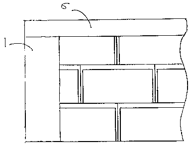
Figure 5 is a front view of a stacked fence wall according to the present
invention;
Figure 6 is a top view of the wall of Figure 5, but without a cap;
Figure 7 is a top view of a course of blocks exhibiting a preferred form of
the present
invention;
Figure 7A is an end view of one of the blocks of Figure 7, adapted for use in
general
construction;
Figure 8 is a top view of a course of blocks exhibiting another preferred form
of the
present invention; and
Figure 9 is a top view of a corner block for use with tlhe block of Figure 7A.
Detailed Descri tn ion
Referring now to the drawings, in Figure 1 there is illustrated a column
element 1 with
flanges extending from the front 3 and rear 4 faces thereof to define channels
5 for receiving
the ends of the blocks.
As shown in Figure 5, the column may be of any desired length. It is anchored
firmly
to the ground, for instance by being bolted and grouted to a footing.
Additional columns are
spaced at regular intervals to define fence posts between whi<;h the blocks of
the present
invention are stacked. The blocks are also stacked on a suitably prepared
surface, that may be
bevelled and provided with footings if desired. Such preparation is
conventional. Moreover,
-2-

CA 02353349 2001-07-20
a column element 1 may be fabricated from block-height column element blocks,
appropriately cemented together to form a column of any desired length.
A cap 6 for use especially along the top edge of a sound barrier fence
according to the
present invention is shown in Figure 2 and Figure 5. It consists of a main
body 7, with
flanges 8 depending downwardly therefrom. The cap 6, which is also of
indeterminate length,
may also be used to finish and end of a wall section, where a full column 1 is
not required.
Blocks for use in connection with the present invention are fabricated from
concrete,
and are shown, in top or plan view in Figures 6, 7 and 8. In l~ figure 6, a
basic form of the
block of the present invention is shown. It consists of a front; wall 9, a
rear wall 10, and
angled end walls 11,12. The front and rear walls 9/10, are joined by a web 13
that is at the
mid-point of the block. The web reinforces the block structurally, and forms a
convenience
point to break the block in two as shown in Figure 6, as will lbe necessary to
insert the block
into a column on alternate courses of a wall, if a running bond pattern of
block placement is
utilized. As shown in Figure 3 and 4, the upper edges 13 of t:he block are
bevelled, and the
lower surface is provided with a shallow groove 14 to interfit: with the top
surface 15 of the
block, with the edges 16 of the groove bearing against the bevelled edges of
the top surface
15 of the block, to permit the block to be stacked easily.
The outermost end edges 17 of the blocks of the embodiment shown in Figure 6
are
bevelled, so that each block in a wall is outlined by top bevelled edges 13
and side bevelled
edges 17, to provide a pleasing masonry appearance.
Referring to Figure 8, a block that is similar to that shown in Figure 6 is
shown.
However, moisture 18, and tension 19 elements are formed in opposing ends of
the block, to
permit a strong interlocking fit between blocks in a course.
Another preferred embodiment of intermitting block is shown in plan in Figure
7.
Each end of the block of Figure 7 is provided with a zig-zag profile having a
major 20 and a
minor 21 peak, and a valley 22 between them. The block exhibits rotational
symmetry,
-3-

CA 02353349 2001-07-20
whereby the major peak 20 at one end is on the opposite side. of the block
from the major
peak at the other, so that the major peak will fit neatly into tlae valley of
an adjoining block. It
will be noted that the blocks of Figures 7 and 8, especially Figure 7, because
they interfit, do
not have to be laid in a running bond pattern, which makes them more
economical to use, and
makes it less necessary to waste any block material during construction. The
block of Figure
7, moreover, may also be used as a dry stack block, with only minor
modification. That is, if
the top surfaces of the ends and central web of the Figure 7 block are
recessed in a semi-
circular pattern 24, as shown in the block marked 'A' in Figmve 7, the blocks
may be stacked
together to form a wall with a substantially hollow core, into which concrete
may be poured.
The purpose of recess 24 is to permit concrete poured into the hollow core of
a wall formed
with such blocks to flow into all block cores smoothly and efficiently.
In Figure 9 are illustrated corner blocks 25a and 25b i:or use with the
construction
block embodiment of Figure 7A. Corner blocks 25a and 25b include a corner
element 26
formed in their side surfaces at one end thereof, and bevelled notches 27 in
their upper
surface corresponding to the lateral edges of the lower surface of the block
flanking the edges
16 of groove 14, thereby to permit a block to be laid at 90 ° on top of
corner block 25.
Corner element 26, it will be observed, corresponds in shape to the zig-zag
profile of
the end of the block of Figure 7A. The blocks shown in Figure 9 are a left
corner block 25a
and a right corner block 25b which is a mirror image thereof.
It is to be understood that the examples described above are not meant to
limit the
scope of the present invention. It is expected that numerous variants will be
obvious to the
person skilled in the field of concrete block design without any departure
from the spirit of
the invention. The appended claims, properly construed, fornn the only
limitation upon the
scope of the invention.
-4-

Representative Drawing
A single figure which represents the drawing illustrating the invention.
Administrative Status

2024-08-01:As part of the Next Generation Patents (NGP) transition, the Canadian Patents Database (CPD) now contains a more detailed Event History, which replicates the Event Log of our new back-office solution.

Please note that "Inactive:" events refers to events no longer in use in our new back-office solution.

For a clearer understanding of the status of the application/patent presented on this page, the site Disclaimer , as well as the definitions for Patent , Event History , Maintenance Fee  and Payment History  should be consulted.

Event History

Description Date
Application Not Reinstated by Deadline 2007-08-03
Inactive: Dead - Final fee not paid 2007-08-03
Deemed Abandoned - Failure to Respond to Maintenance Fee Notice 2007-07-20
Deemed Abandoned - Conditions for Grant Determined Not Compliant 2006-08-03
Inactive: IPC from MCD 2006-03-12
Notice of Allowance is Issued 2006-02-03
Letter Sent 2006-02-03
Notice of Allowance is Issued 2006-02-03
Inactive: Approved for allowance (AFA) 2006-01-05
Amendment Received - Voluntary Amendment 2005-07-22
Inactive: S.30(2) Rules - Examiner requisition 2005-02-04
Amendment Received - Voluntary Amendment 2004-08-27
Inactive: S.30(2) Rules - Examiner requisition 2004-03-01
Inactive: S.29 Rules - Examiner requisition 2004-03-01
Amendment Received - Voluntary Amendment 2003-11-14
Inactive: Entity size changed 2003-07-15
Inactive: S.30(2) Rules - Examiner requisition 2003-05-22
Application Published (Open to Public Inspection) 2003-01-20
Inactive: Cover page published 2003-01-19
Inactive: IPC assigned 2001-09-06
Inactive: First IPC assigned 2001-09-06
Inactive: Filing certificate - RFE (English) 2001-08-10
Application Received - Regular National 2001-08-09
Request for Examination Requirements Determined Compliant 2001-07-20
All Requirements for Examination Determined Compliant 2001-07-20

Abandonment History

Abandonment Date Reason Reinstatement Date
2007-07-20
2006-08-03

Maintenance Fee

The last payment was received on 2006-07-05

Note : If the full payment has not been received on or before the date indicated, a further fee may be required which may be one of the following

  • the reinstatement fee;
  • the late payment fee; or
  • additional fee to reverse deemed expiry.

Patent fees are adjusted on the 1st of January every year. The amounts above are the current amounts if received by December 31 of the current year.
Please refer to the CIPO Patent Fees web page to see all current fee amounts.

Fee History

Fee Type Anniversary Year Due Date Paid Date
Request for examination - small 2001-07-20
Application fee - small 2001-07-20
MF (application, 2nd anniv.) - standard 02 2003-07-21 2003-06-20
MF (application, 3rd anniv.) - standard 03 2004-07-20 2004-06-21
MF (application, 4th anniv.) - standard 04 2005-07-20 2005-06-23
MF (application, 5th anniv.) - standard 05 2006-07-20 2006-07-05
Owners on Record

Note: Records showing the ownership history in alphabetical order.

Current Owners on Record
TONY J. AZAR
Past Owners on Record
None
Past Owners that do not appear in the "Owners on Record" listing will appear in other documentation within the application.
Documents

To view selected files, please enter reCAPTCHA code :


To view images, click a link in the Document Description column (Temporarily unavailable). To download the documents, select one or more checkboxes in the first column and then click the "Download Selected in PDF format (Zip Archive)" or the "Download Selected as Single PDF" button.

List of published and non-published patent-specific documents on the CPD .

If you have any difficulty accessing content, you can call the Client Service Centre at 1-866-997-1936 or send them an e-mail at CIPO Client Service Centre.

({010=All Documents, 020=As Filed, 030=As Open to Public Inspection, 040=At Issuance, 050=Examination, 060=Incoming Correspondence, 070=Miscellaneous, 080=Outgoing Correspondence, 090=Payment})


Document
Description 
Date
(yyyy-mm-dd) 
Number of pages   Size of Image (KB) 
Representative drawing 2002-03-05 1 6
Description 2003-11-13 4 194
Claims 2003-11-13 2 43
Abstract 2001-07-19 1 10
Description 2001-07-19 4 207
Claims 2001-07-19 2 54
Drawings 2001-07-19 5 72
Description 2004-08-26 4 197
Claims 2004-08-26 2 45
Description 2005-07-21 4 203
Claims 2005-07-21 2 46
Filing Certificate (English) 2001-08-09 1 175
Reminder of maintenance fee due 2003-03-23 1 107
Commissioner's Notice - Application Found Allowable 2006-02-02 1 161
Courtesy - Abandonment Letter (NOA) 2006-10-11 1 167
Courtesy - Abandonment Letter (Maintenance Fee) 2007-09-16 1 177
Fees 2003-06-19 1 34
Fees 2004-06-20 1 34
Fees 2005-06-22 1 34
Fees 2006-07-04 1 39