Note: Descriptions are shown in the official language in which they were submitted.
CA 02353838 2001-06-04
WO 00/35647 PCT/US99/29599
METHODS AND APPARATUS FOR BLOW MOLDING
USING MICROGRAINED PATTERNS
BACKGROUND OF THE INVENTION
The present invention relates to molding processes and apparatus and to blow
molded
articles. Specifically, the present invention relates to blow molding
processes and apparatus
which improve the venting of trapped air from molded material and which
improve the surface
finish on molded articles, such as automobile fascias, bumpers or other body
colnponents.
Fundamentally, blow moldinL is a manufacturing technique that involves the use
of
coinpressed gas to expand material, usually a thennoplastic, outward against
the inner walls of
a surrounding, split-cavity mold. In extrusion blow molding methods and
apparatus, molding
is accomplished by first extruding a preselected length of material, for
example, heat-softened
thermoplastic, into a tubular preform, also called a parison. The parison is
then surrounded, and
usually pinched at one or more locations, by the split-cavity mold. A blow pin
is then inserted
into the parison and compressed gas is injected through the blow pin to
inflate the parison, much
like a balloon, against the sides of the mold. Typically, low gas pressures
are used. Contact of
the thermoplastic material with the mold causes the material to cool and
harden in the desired
shape. The split-cavity mold is then separated and the molded article is
removed.
In the manufacture of blow molded articles such as automobile body components,
it is
often desirable to provide a very smooth, aesthetically pleasing surface
finish. However, it is
difficult to obtain smooth, high quality surface finishes on products molded
using conventional
blow molding techniques without further surface finislling, such as sanding
and painting. This
difficulty arises, in part, fi-om the presence of air or other gas at or near
the surface of the molded
article. Trapped air or gas may cause variations or defects in the surface
finish of the molded
product. Blow molding is especially susceptible to the undesireable effects of
trapped air because
of the use of compressed gases in the molding process and because of the
displacement of air
from the mold due to the expansion of the parison.
Conventional blow molding techniques have addressed this problem by providing
vent
holes at spaced intervals on the mold surface to facilitate venting of trapped
air. However, vent
holes provide for venting of trapped air only in local regions on the surface
of the molded
product; some trapped air may not reach vent holes during the molding process.
To provide more
uniform venting, it is known to utilize porous metal molds. However, porous
molds are prone
to clogging after repeated use and require additional effort to maintain.
Thus, there remains a
CA 02353838 2001-06-04
WO 00/35647 PCT/US99/29599
need for blow molding processes and apparatus which provide uniform and
sufficient venting of
trapped air and high quality surface finishes, yet which do not require
significant maintenance
effort.
SUMMARY OF THE INVENTION
The aforementioned problems are eliminated and desired advantages are realized
by the
present invention, which contemplates new and improved processes and apparatus
for blow
molding by providing mold surfaces with micrograined patterns to improve
venting and surface
finish. The micrograined patterns are preferably in the form of a pattern of
projections which
define between them a network of interconnected channels. The projections are
of a sufficient
height that they engage the outer surface of the fully-expanded parison. The
channels are of a
sufficient depth that, when the parison engages the projections, the channels
form venting
passages with the parison surface to pennit trapped air to escape and migrate
through vent holes
which communicate with the channels. The dimensions of the projections are
selected to provide
for the formation of venting passages while preventing the formation of
patterns in the surface
of the molded product.
In one aspect, the invention may be defined as an apparatus for molding
articles, the
apparatus comprising a mold having a mold surface provided with a micrograined
pattern which
facilitates the formation of venting passages with the surface of an expanded
parison. More
particularly, the invention may be defined as an apparatus for blow molding
articles in which the
mold surface is provided with a micrograined patteni that includes projections
of a substantially
circular or parallelogram shape, the projections defning a network of
interconnected channels
which form venting passages with the surface of the expanded parison.
In another aspect, the invention may be defined as a process for blow molding
articles,
the process comprising the steps of: a) providing a parison of material to be
expanded outward
into a mold; b) providing a mold having a mold surface including a
micrograined pattern; c)
providing a parison of material within the mold; d) expanding the parison
outward against the
mold surface such that an outer surface of the parison forms venting passages
with the
micrograined pattern. More particularly, the invention may be defined as a
process for blow
molding articles, the process comprising the steps of: a) providing a parison
of material to be
expanded outward into a mold; b) providing a mold having a mold surface
including a
micrograined pattenl, the pattern including projections of a substantially
circular or parallelogram
CA 02353838 2001-06-04
WO 04/35647 PCT/US99/29599
3
shape defining a network of interconnected channels; c) providing a parison of
material within
the mold; d) expanding the parison outward against the mold surface such that
an outer surface
of the parison engages the projections and forms venting passages with the
channels.
In yet another aspect, the invention may be defined as a blow-molded article,
fornzed by
a process comprising the steps of: a) providing a parison of material to be
expanded outward into
a mold; b) providing a mold having a mold surface including a micrograined
pattern; c) providing
a parison of material within the mold; d) expanding the parison outward
against the mold surface
such that an outer surface of the parison foi7ns venting passages with the
micrograined pattern.
More particularly, the invention may be defined as a blow-molded article,
forined by a process
comprising the steps of: a) providing a parison of material to be expanded
outward into a mold;
b) providing a mold having a mold surface including a micrograined pattern,
the pattern
including projections of a substantially circular or parallelogram shape
defining a network of
interconnected channels; c) providing a parison of material within the mold;
d) expanding the
parison outward against the mold surface sucll that an outer surface of the
parison engages the
projections and forms venting passages with the channels.
BRIEF DESCRIPTION OF THE DRAWINGS
The accompanying drawings which are incorporated into and form a part of the
specification, illustrate embodiments of the present invention and, together
with the description,
serve to explain the principles of the invention. The drawings are only for
the purpose of
illustrating preferred embodiments of the invention and are not to be
construed as limiting. In
the drawings, in which like numbers refer to like parts throughout:
FIG. 1 is an illustration of a blow molding process and apparatus according to
a preferred
embodiment of the present invention;
FIG. 2 is an isometric of a blow mold surface according to another preferred
embodiment
of the present invention;
FIG. 3A is a top view of a blow mold surface according to another preferred
embodiment
of the present invention;
FIG. 3B is a cross-section of the surface taken along line 3B-3B of FIG. 3A;
FIG. 4A is a top view of a blow mold surface according to another preferred
embodiment
of the present invention; and
FIG. 4B is a cross-section of the surface taken along line 4B-4B of FIG. 4A.
CA 02353838 2001-06-04
WO 00/35647 PCTIUS99/29599
4
DESCRIPTION OF THE PREFERRED EMBODIMENTS
Referring to FIG. lA, an extrusion blow molding apparatus 8, according to the
present
inveiition, includes a split-cavity mold 10 comprised of two movable half poi-
tions. With the half
portions separated, a tubular parison 12 of a preselected length of extruded
material, typically a
thennoplastic such as polyethylene or polypropylene, exits from an extrusion
die 14 into the
space between the half portions.
Referring to FIG. 1B, after the parison 12 is extruded to the appropriate
length, the half
portions of the mold 10 are brought together to define a mold cavity 16. The
parison 12 is
pinched at top and bottom ends between the half portions. A gas injection
device 18, including
a blow pin 20 that extends through a hole (not shown) in mold 10, introduces
compressed gas
into the parison cavity 22, thereby expanding the parison 12 outward against
the inner surface
24 of the mold 10. As shown in FIG. 1 C, the half portions are then separated
to permit reinoval
of the blow molded article 26.
FIG. 1D is a magnified view of a portion of FIG. 1B showing the interaction
between the
outer surface 30 of the expanding parison 12 aiid the inner surface 24 of the
mold 10. Mold
surface 24 is provided with a series of vent holes 32 (two shown) spaced at
regular intervals to
permit the escape of trapped gas from the mold as the parison 12 expands
outward in the
direction of the arrows in FIG. 1D.
The blow molding process described above is characteristic of conventional
blow
molding techniques and may be used in conjunction with the features of the
present invention,
which relates particularly to the mold surface. Referring now to FIG. 2, which
is an isometric
of a section of a mold surface according to a preferred embodiment of the
invention, the mold
surface 24 is provided with a micrograined pattern having a series of raised
projections 40 which
define a network of channels 42 therebetween. In FIG. 2, the channels 42 are
shown parallel to
one another. It will be understood that the channels 42 may be interconnected
by cross-channels
(not shown) which extend in a generally orthogonal direction to the extent of
the channels
illustrated. The channels 42 communicate with vent holes (not shown in FIG. 2)
to permit air
to vent out of the mold.
In accordance with the present invention, the spacing of the peaks of raised
projections
40 and the depth of channels 42 are selected to maximize venting capabilities
while preventing
the formation of visibly detectable patterns on the surface of the molded
article. A deptli range
of between 10 and 40 microns is preferred.
CA 02353838 2001-06-04
WO 00/35647 PCT/US99/29599
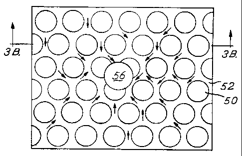
FIG. 3A is a top magnified view of a mold surface pattern according to another
preferred
embodiment of the present invention. The niicrograined patteni is in the form
of a series of
circular projections 50 ananged in rows, with the centers of circular
projections of adjacent rows
being offset. The circular projections 50 define a network of interconnected
channels 52 which
5 communicate with vent holes 56 (one shown). The channels 52 are of an
irregular shape and
varying width, as defined by the circular periphery of the projections 50.
Referring to the cross-
section shown in FIG. 3B, the circular projections 50 have a flat upper
surface 58 and rounded
edges 59. The bottom of channels 52 is of a generally rounded shape, defining
an undulating
mold surface 54. The circular periphery of the projections 50 fonn the
channels 52 of varying
width and non-linear pathway from points on the mold to the vent holes 56. The
offset centers
of the circular projections 50 reduce the likelihood that noticeable
micrograined patterns will
appear in the finished molded article.
FIG. 4A is a top magnified view of a mold surface pattern according to another
preferred
embodiment of the present invention. Here, projections 60 are shaped generally
as a
parallelogram and define a network of channels 62 which communicate with vent
holes 66 (one
shown). Referring to the cross-section shown in FIG. 4B, the projections 60
have a flat upper
surface 68 and rounded edges 69. The bottoms of channels 62 are of a generally
rounded shape.
The generally flat peripheral surfaces of the projections 60 fonn
interconnected linear channels
62 which provide for efficient evacuation of escaping air from the mold.
Those of ordinary skill will recognize that the aforementioned surface
patterns with
defined channels provide for the formation of venting passages witli the
surface of the expanded
parison during molding. The surface patterns may be fonned by conventional
mold surface
preparation techniques, such as by etching or laser machining. It will also be
appreciated by
those of ordinary slcill, that dimensions of the mold surface pattern are
selected to provide for the
formation of venting passages with the surface of the expanded parison. Thus,
the dimensions
will depend on a number of factors, including the fluid and shrinkage
characteristics of the
molded material and the pressure applied to the parison during molding. For
example, the depth
of the projections for a molding process at a given pressure is preferably
less than the depth of
the projections for a molding process at a higher pressure because higher
molding pressures will
tend to force the material deeper into the channels and eliminate the venting
passages that would
otherwise be formed.