Note: Descriptions are shown in the official language in which they were submitted.
CA 02354001 2001-06-06
WO 00!40794 PCT/US99/30887
STORM PROOF ROOFING MATERIAL
TECHNICAL FIELD AND INDUSTRIAL
APPLICABILITY OF THE INVENTION
This invention relates to asphalt-based roofing materials, and in particular
to a
roofing material having improved durability and impact resistance to withstand
the
destructive forces of storms.
BACKGROUND OF THE INVENTION
to Asphalt-based roofing materials, such as roofing shingles, roll roofing and
commercial roof ng, are installed on the roofs of buildings to provide
protection from the
elements. Typically, the roof ng material is constructed of a substrate such
as a glass fiber
mat or an organic felt, an asphalt coating on the substrate, and a surface
layer of granules
embedded in the asphalt coating.
15 The typical roofing material construction is suitable under most
circumstances.
However, sometimes a roofing material is subjected to environmental conditions
that may
damage the roofing material. For example, storms are responsible for billions
of dollars
in damage to roofing materials every year. During storms, hailstones may
impact the
roofing material, which may cause tears or punctures in the roofing material.
The
2o hailstone impacts may also cause an immediate loss of some granules from
the impacted
areas of the roofing material and a further loss of granules from those areas
over time.
The loss of granules creates an unattractive appearance and leaves the asphalt
coating in
those areas unprotected from the degrading effects of the elements.
Accordingly, there is
a need for a roofing material having an improved ability to withstand the
destructive
25 forces of storms.
The prior art does not adeduately address the need for a storm proof roofing
material. For example, U.S. Patent Nos. 5,380,SS2 and 5,516,573, both issued
to George
et al., disclose a method of improving the adhesion of granules to a roofing
shingle, by
spraying a thin stream of a low viscosity adhesive to cover 50-7S% of the
surface of the
3o asphalt coating before applying the granules. The patents teach that
granule loss is caused
by moisture disrupting the bond between the granule and the asphalt coating.
There is no
suggestion that granule loss may be related to changes in the a.;phalt coating
over time, or
CA 02354001 2001-06-06
WO 00!40794 PCT/US99/30887
that sufficiently covering the asphalt coating with the adhesive may reduce
these changes
and the resultant granule loss.
It is known to apply a surface coating onto a roof after the roofing shingles
have
been installed to protect the shingles from granule loss and other damage.
Unfortunately,
surface coatings require additional labor to apply after the roofing shingles
have been
installed, they are relatively expensive, and they may create safety problems
by producing
a slick roof.
Several patents disclose roofing materials constructed with multiple
substrates.
For example, U.S. Patent No. 5,326,797, issued to Zimmerman et ai., discloses
a roofing
shingle including a top mat of glass fibers and a bottom mat of polyester. The
patent is
related to a fire-resistant shingle, and there is no mention of improved
impact resistance.
Also, there is no suggestion of improved bonding between the polyester mat and
the
asphalt coating.
U.S. Patent No. S,S71,S96, issued to Johnson, discloses a roofing shingle
including an upper layer of directional fiber such as Kevlar fabric, a middle
layer of
fibrous mat material such as glass fiber mat, and a lower layer of directional
fiber such as
E-glass fabric. The upper fiber layer is described as being important to
shield the shingle
from hail impact damage. The lower layer of E-glass fabric is not effective
for improving
the impact resistance of the shingle.
2o U.S. Patent No. 5,822,943, issued to Frankoski et al., discloses an asphalt-
coated
roofing shingle including a scrim and a mat. The scrim is bonded to the mat
with
adhesive; there is no suggestion of improved bonding between the scrim and the
asphalt
coating. A scrim is not very effective for improving.the impact resistance of
a roofing
shingle.
A journal article, "Ballistic Impact Resistance of SMA and Spectra Hybrid
Graphite Composites", Journal of Reinforced Plastics and Composites, Vol. 17,
2/1998,
by Ellis et aL, discloses placing energy absorbing fibers on the back surface
of a graphite
composite. The fibers were found to provide only a slight improvement in the
impact
strength of the composite. The journal article is not related to roofing
materials.
It is known to manufacture roofing materials with rubber-modified asphalt to
provide some improvement in impact resistance. Unfortunately, roofing
materials made
witf~ rubber-modified asphal' more difficult to manufacture, handle, store and
install,
and they are more expensive, than roofing materials made with conventional
roofing
2
CA 02354001 2001-06-06
WO 00/40794 PCT/US99/30887
asphalt. Also, the. rubber-modified asphalt shingles are not very effective in
resisting
impacts. Accordingly, there is still a need for a roofing material having
improved
durability and impact resistance to better withstand the destructive forces of
storms.
SUMMARY OF THE INVENTION
The above objects as well as others not specifically enumerated are achieved
by an
asphalt-based roofing material according to the present invention. The roofing
material
includes a substrate coated with an asphalt coating, a protective coating
adhered to the
upper surface of the asphalt coating, a surface layer of granules adhered to
the protective
to coating, and a web bonded to the lower region of the asphalt coating. The
combination of
the protective coating and the web provides a roofing material having both
improved
durability and improved impact resistance. As a result, the roofing material
is better able
to withstand the destructive forces associated with storms.
In another embodiment, the roofing material includes a substrate coated with
an
~5 asphalt coating, a protective coating adhered to the upper surface of the
asphalt coating,
and a surface layer of granules adhered to the protective coating. The
protective coating
covers at least about 80% of the upper surface of the asphalt coating in the
exposed
portion of the roofing material.
The present invention also relates to a method of manufacturing the storm
proof
2o roofing material. The method includes the steps of coating a substrate with
an asphalt
coating, applying a protective coating to the upper surface of the asphalt
coating, applying
a surface layer of granules to the protective coating, and applying a web to
the lower
region of the asphalt coating.
in another embodiment, the method includes the steps of applying a web to a
25 substrate, coating the substrate and the web with an asphalt coating, where
the web is in
contact with the lower region of the asphalt coating, applying a protective
coating to the
upper surface of the asphalt coating, and applying a surface layer of granules
to the
protective coating.
in another embodiment, the method includes the steps of coating a substrate
with
30 an asphalt coating, moving the asphalt-coated substrate at a speed of at
least about 200
feetlminute (bl meters/rninute) past an applicator to apply a continuous layer
of protective
coating to the upper surface of the asphalt coating, and applying a surface
layer of
granules to the protective coating. The rapid movement of the asphalt-coated
substrate
CA 02354001 2001-06-06
WO 00140794 PCT/US99/30$87
creates a boundary layer of air on the upper surface of the asphalt coating,
which can
create discontinuities in the protective coating. The applicator is positioned
sufficiently
close to the upper surface of the asphalt coating to minimize the boundary
layer and
thereby substantially reduce discontinuities in the protective coating.
In a further embodiment, the method includes the steps of coating a substrate
with
an asphalt coating, providing a solid or molten film of a protective coating
material,
applying the film to the upper surface of the asphalt coating, and applying a
surface layer
of granules to the film.
Various objects and advantages of this invention will become apparent to those
1o skilled in the art from the following detailed description of the preferred
embodiments,
when read in light of the accompanying drawings.
BRIEF DESCRIPTION OF THE DRAWINGS
Fig. I is a schematic view in elevation of apparatus for manufacturing an
asphalt-
15 based roofing material according to the invention.
Fig. 2 is a perspective view of part of the manufacturing apparatus of Fig. 1,
showing an applicator applying films of protective coating onto the upper
surface of an
asphalt-coated sheet.
Fig. 3 is a cross-sectional view of an alternate embodiment of an applicator
2o applying a film of protective coating onto the upper surface of an asphalt-
coated sheet.
Fig. 4 is an enlarged cross-sectional view of an asphalt-based roofing
material
according to the invention.
Fig. S is a further enlarged cross-sectional view of the upper portion of an
asphalt-
based roofing material according to the invention.
25 Fig. 6 is a perspective view of a prior art roofing shingle installed on a
roof,
showing a loss of granules after a period of time caused by impacts on the
roofing shingle.
Fig. 7 is a perspective view of a roofing shingle according to the invention
installed on a roof, showing substantially no granule loss over the same
period of time
after being impacted.
3o Fig. 8 is a perspective view of part of the manufacturing apparatus of Fig.
1,
showing apparatus for applying webs to the lower surface of a sheet of asphalt-
coated
substrate.
4
CA 02354001 2001-06-06
WO 00/40794 PCT/US99/30887
Fig. 9 is a schematic view in elevation of an alternate embodiment of the
apparatus
of Fig. 8, showing the web being applied to the lower surface of a substrate
before coating
the web and substrate with asphalt coating.
Fig. 10 is an enlarged perspective view, partially in cross-section, of a two-
component web for use in an asphalt-based roofing material according to the
invention.
Fig. 11 is a further enlarged cross-sectional view of the web of Fig. 10 in
contact
with an asphalt coating, showing the second component of the web intermingled
by
melting with a portion of the asphalt coating.
Fig. 12 is an enlarged perspective view, partially in cross-section, of a
sheath/core
l0 fiber of.a web for use in an asphalt-based roofing material according to
the invention.
Fig. 13 is a further enlarged cross-sectional view of the sheath/core fiber of
Fig. 12
surrounded by an asphalt coating, showing the sheath of the fiber intermingled
by melting
with a portion of the asphalt coating.
Fig. 14 is a top view of a sheet of roofing material manufactured with the
15 apparatus of Fig. 1, showing the roofing material after being cut but
before separation into
roofing shingles.
Fig. 15 is a perspective view of several three-tab roofing shingles according
to the
invention installed on the side of a roof.
Fig. I6 is a perspective view of a hip and ridge roofing shingle according to
the
2o invention installed on the ridge of a roof.
Fig. 17 is a perspective view of a laminated roofing shingle according to the
invention.
DETAILED DESCRLPTION AND PREFERRED
25 EMBODIMENTS OF THE INVENTION
Refernng now to the drawings, there is shown in Fig. 1 an apparatus 10 for
manufacturing an asphalt-based roofng material according to the invention. The
illustrated manufacturing process involves passing a continuous sheet 12 in a
machine
direction (indicated by the arrows) through a series of manufacturing
operations. The
3o sheet usually moves at a speed of at least about 200 feetlminute (bi
rneters/minute), and
typically at a speed within the range of between about 450 feetlminute (137
meters/minute) and about 800 feet/minute (244 meters/minute). Although the
invention is
shown and described in terms of a continuous process, it should be understood
that the
CA 02354001 2001-06-06
WO 00/40794 PCT/US99/30887
invention can also be practiced in a batch process using discreet lengths of
materials
instead of continuous sheets.
In a first step of the manufacturing process, a continuous sheet 12 of
substrate is
payed out from a roll 14. The substrate can be any type known for use in
reinforcing
asphalt-based roofing materials, such as a web, scrim or felt of fibrous
materials such as
mineral fibers, cellulose fibers, rag fibers, mixtures of mineral and
synthetic fibers, or the
like. Combinations of materials can also be used in the substrate. Preferably,
the
substrate is a nonwoven web of glass fibers.
The sheet of substrate is passed from the roll through an accumulator 16. The
accumulator allows time for splicing one roll of substrate to another, during
which time
substrate within the accumulator is fed to the manufacturing process so that
the splicing
does not interrupt manufacturing.
Next, the sheet is passed through a coater 18 where an asphalt coating is
applied to
the sheet. The asphalt coating can be applied in any suitable manner. In the
illustrated
embodiment, the sheet is submerged in a supply of hot, melted asphalt coating
to
completely cover the sheet with the tacky coating. However, in other
embodiments, the
asphalt coating could be sprayed on, rolled on, or applied to the sheet by
other means.
When an organic felt is used as the substrate, it may be desirable to first
saturate the felt
with a saturant asphalt, and then coat the upper and lower surfaces of the
felt with an
asphalt coating containing a filler.
The term "asphalt coating" means any type of bituminous material suitable for
use
on a roofing material, such as asphalts, tars, pitches, or mixtures thereof.
The asphalt can
be either a manufactured asphalt produced by refining petroleum or a naturally
occurring
asphalt. The asphalt coating can include various additives and/or modifiers,
such as
inorganic fillers or mineral stabilizers, organic materials such as polymers,
recycled
streams, or ground tire rubber. Preferably, the asphalt coating contains an
asphalt and an
inorganic filler or mineral stabilizer. Unlike some previous roofing
materials, there is no
need to modify the asphalt with rubber or similar polymers to improve the
durability of
the roofing material.
The roofing material of the present invention is provided with improved
durability
by the application of a protective coating to the upper surface of the asphalt
coating. One
aspect of the improved durability is a reduction in the loss of granules,
which may be
caused by hailstones during storms in addition to natural weathering. As shown
in Fig. 1,
6
CA 02354001 2001-06-06
WO 00/40794 PCT/US99/30887
the asphalt-coated sheet 20 is passed beneath an applicator 22, where a
protective coating
is applied to the upper surface of the asphalt coating. The sheet is then
passed beneath a
granule dispenser 24 for the application of granules to the protective
coating. After
deposit of the granules, the sheet is turned around a slate drum 26 to press
the granules
into the asphalt coating and to temporarily invert the sheet.
The protective coating can be applied to the upper surface of the asphalt
coating
by any method suitable for forming a layer that is effective to improve the
durability of
the roofing material. In a preferred embodiment, the protective coating is
applied as a
film, which can be a solid, semisolid or molten film. Fig. 2 illustrates an
applicator 22 for
applying a pair of molten films 28 of protective coating onto the upper
surface 30 of the
asphalt-coated sheet 20. The sheet can include single or multiple lanes. Four
lanes 32 are
shown in the illustrated embodiment (indicated by the dotted lines), so that
the sheet can
be cut into roof ng shingles. In the illustrated embodiment, each of the lanes
includes a
prime portion 34 that is normally exposed to the elements when the roofing
material is
installed on a roof, and a headlap portion 36 that is normally covered by
adjacent shingles
when the roofing shingle is installed on the roof. Preferably, the films of
protective
coating are applied to the prime portions of the sheet, but not to the headlap
portions.
Application of the protective coating to just the prime portions of the sheet
provides
improved durability to the portion of the roofing shingle exposed to the
elements on a
roof, while minimizing the overall cost of the roofing material. However, a
film of
protective coating can also be applied to cover the entire sheet.
The applicator shown in Fig. 2 includes a support shoe 38, for a purpose that
will
be described below. Single or multiple dies can be mounted in openings in the
support
shoe, two dies 40 in the illustrated embodiment, and secured by fasteners such
as brackets
42. Each of the dies includes a slot 44 that faces downwardly toward the
asphalt coating,
and that is oriented transversely to the direction 46 of movement of the
sheet. The dies
are supplied through heated feed hoses 48 with melted protective coating that
is pumped
from a storage tank (not shoum). The melted protective coating is extruded as
a film 28
through the slot of each die onto the upper surface of the asphalt coating.
The support
shoe prevents the formation of ridges or wakes in the protective coating along
the sides of
the slot during application of the film.
It was found that the rapid movement of the asphalt-coated sheet creates a
boundary layer of air on the upper surface of the sheet, and that when the
protective
CA 02354001 2001-06-06
WO OOI40794 PCTIUS99/30887
coating is applied, the boundary layer can cause the protective coating to be
discontinuous
across the area of intended application instead of continuous. In a preferred
embodiment,
the applicator is positioned sufficiently close to the upper surface of the
asphalt coating to
minimize the boundary layer and thereby significantly reduce discontinuities
in the
protective coating. Preferably, the protective coating forms a layer that is
at least about
90% continuous {not more than 10% open areas), and more preferably it forms a
substantially completely continuous layer. As shown in Fig. 2; the support
shoe 38 and
dies 40 of the applicator are positioned just in contact with the upper
surface 30 of the
asphalt-coated sheet 20. Preferably, the applicator is positioned within about
0.1 inch
to (0.254 cm) of the upper surface.
Fig. 3 illustrates another preferred applicator 50 for applying a film 52 of
protective coating onto the upper surface 54 of an asphalt-coated sheet 56. A
die 58 is
mounted on a die mount 60 positioned above the sheet. The die includes a slot
62 that
faces downwardly toward the asphalt coating, and that is oriented transversely
to the
i 5 direction 64 of movement of the sheet. The die and slot are positioned a
distance D of
within about 0.1 inch (0.254 cm) from the upper surface of the sheet. The die
is supplied
through a heated supply line 66 with melted protective coating that is pumped
from a
storage tank (not shown). The melted protective coating is extruded through
the slot as a
film 52 onto the upper surface of the asphalt-coated sheet.
20 Many other methods can be used for applying the protective coating to the
upper
surface of the asphalt coating. One method is paying out a previously extruded
film of the
protective coating material onto the asphalt-coated sheet. Another method is
adding
protective coating material in particulate form to the upper surface of the
asphalt-coated
sheet, and then heating the protective coating material to melt it and cause
it to flow into a
25 substantially continuous layer. A further method is pre-mixing the
protective coating
material in particulate form into the asphalt coating, so that the protective
coating material
melts and phase separates from the asphalt coating when the asphalt coating is
heated, to
provide a substantially continuous layer on the asphalt coating. Other
suitable methods
include spraying and roll coating. Preferably, the protective coating is fluid
enough when
3o the granules are applied that it flows partially around the granules to
adhere them to the
coating. In a preferred embodiment, the protective coating is applied
immediately after
the asphalt coating is applied and immediately before the granules are
applied.
CA 02354001 2001-06-06
WO 00/40794 PCT/US99/30887
Preferably, the protective coating covers at least about 80% of the upper
surface of
the asphalt coating, in the portion of the roofing material that is exposed on
a roof. More
preferably, the protective coating substantially completely covers the upper
surface of the
asphalt coating in the exposed portion. As shown in Fig. 2, the films of
protective coating
28 completely cover the prime (exposed) portions 34 of the roofing material.
The
protective coating preferably has an average thickness of at least about 1 mil
(0.025 mm),
and more preferably at least about 3 mils (0.076 mm). However, the protective
coating is
not so thick that it covers the granules and leaves a glossy appearance on the
surface of
the roofing material. Preferably, the protective coating has an average
thickness of not
1o greater than about 60 mils (1.5 mm). Covering the asphalt coating with the
protective
coating reduces granule loss.
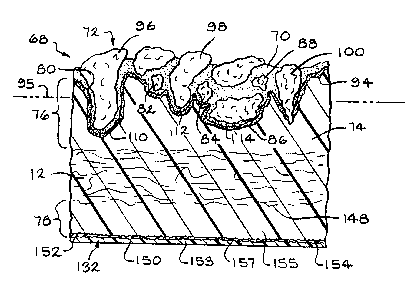
Figs. 4 and 5 illustrate a roofing material 68 according to the invention with
an
applied protective coating 70 and a layer of granules 72. The roofing material
includes a
substrate 12 that is coated with an asphalt coating ?4. The asphalt coating
includes an
15 upper region 76 that is positioned above the substrate 12 when the roofing
material is
installed on a roof, and a lower region 78 that is positioned below the
substrate. The
upper region includes an upper surface 80. The protective coating 70 is
adhered to the
upper surface of the asphalt coating. The surface layer of granules 72 is
adhered to the
protective coating.
20 It is believed that the protective coating improves the adhesion of the
granules by
several possible different mechanisms. The granules may adhere more strongly
to the
protective coating than the asphalt coating, because of the different
compositions of the
protective coating and the asphalt coating. In some embodiments, the
protective coating
completely envelops a middle layer of granules to adhere the granules to the
roofing
25 material. Preferably, from about 0.5% to about 6% of the total granules are
enveloped. In
Fig. 4, the protective coating 70 envelops the granules 82, 84, 86 and 88, and
in Fig. 5, the
protective coating 70 envelops the granules 90 and 92.
The protective coating also adheres strongly to the asphalt coating. In the
illustrated embodiment, an interphase region 94 comprises a portion of the
protective
30 coating 70 which has been intermingled with a portion of the asphalt
coating 74 by
melting and mixing, because of the partial miscibility of the protective
coating with the
asphalt coating. The intermingling strongly adheres the protective coating to
the asphalt
coating. Some protective coating materials are miscible with the asphalt
coating, and
CA 02354001 2001-06-06
WO 00140794 PCT/US99/30887
others are °not miscible. In some embodiments of the invention, the
protective coating
adheres strongly to the asphalt coating without such intermingling.
As shown in the drawings, the granules 72 have been pressed down into the
protective coating 70. Usually, at least a portion of the granules penetrate
the asphalt
coating 74. "Penetrate" means that a granule extends past an asphalt coating
line 95
which is an average upper surface 80 of the asphalt coating 74. In Fig. 4, the
granules 96,
98, 84, 86 and 100 penetrate the asphalt coating, and in Fig. 5, the granules
90, 102 and
104 penetrate the asphalt coating. In some embodiments of the invention, a
substantially
continuous layer of the protective coating is maintained between the asphalt
coating and
1o the granules that penetrate the asphalt coating. In Fig. 4, layers 110, 112
and 114 of the
protective coating are maintained between the granules 96, 98 and 86 and the
asphalt
coating, and in Fig. 5, a layer i 16 is maintained between the granule 104 and
the asphalt
coating. It was believed beforehand that when a granule was pressed through
the layer of
protective coating into the asphalt coating, the protective coating layer
might not be
is maintained between the granule and the asphalt coating. Preferably, a
substantially
continuous layer of the protective coating is maintained between the asphalt
coating and
at least about 30% of the granules that penetrate the asphalt coating. The
continuous layer
of protective coating around the granules increases the adhesion of the
granules to the
roofing material.
20 Additionally, the protective coating may provide a seal to prevent outside
moisture
from flowing around the granules to the asphalt coating. This may help to
prevent
degradation of the roofing material. In Fig. 4, the protective coating may
provides a seal
to.prevent moisture-from flowing around the granule 100 to the asphalt
coating, even
though the granule penetrates the asphalt coating. The protective coating
forms a tight
25 seal completely around the perimeter of the granule. Similarly, in Fig. 5,
the protective
coating provides a seal around the granule 102.
The protective coating can be any material suitable for forming a layer that
is
effective to improve the durability of the roofing material, such as any type
of
thermoplastic, thermoset, or asphalt-based polymeric materials. In a preferred
3o embodiment, the polymeric material functions as an adhesive. Similarly, the
adhesive can
include any type of thermoplastic, thermoset, ar asphalt-based adhesive that
is effective to
adhere the granules to the asr' '* coating. Some examples of suitable hot-melt
adhesives
include ethylene-vinyl acetate copolymers, ethylene-ethyl acetate copolymers,
ethylene-n-
CA 02354001 2001-06-06
WO 00/40'194 PCT/US99/30887
butylacrylate polymers, ethylene-methacrylate polymers, styrene-isoprene-
styrene block
or graft copolymers, styrene-butadiene-styrene block or graft copolymers,
other styrene-
containing block or graft copolymers, polyamide terpolymers, hydrocarbon
rubbers,
polyethylenes, polyesters, polyurethanes, siioxanes, and mixtureslcombinations
of these
materials. Preferred adhesives for use in the invention are flexible ethylene-
vinyl acetate
copolymers, ethylene-vinyl acetate copolymers modified with styrene-butadiene-
styrene
block copolymers, and tackified polyethylenes. Preferably, the adhesive is
selected so
that it adheres to the roofing granules predominantly by polar bonding. For
example,
ethylene-vinyl acetate copolymers adhere to conventional coated (painted)
roofing
to granules predominantly by polar bonding. The adhesive can be modified with
materials
such as styrene butadiene polymers, poiyolefin polymers, styrene isoprene
polymers,
petroleum derived tackifying resins, rosin derived tackifying resins, terpene
derived
tackifying resins, paraffin waxes and oils, microcrystalline waxes and oils,
and napthanic
waxes and oils.
is A stabilizer can be added to the protective coating to tailor the
protective coating
to specialized conditions, such as extreme exposures of ultraviolet light,
solar radiation,
and/or temperature. The protective coating can also contain other additives
such as
algicides, fungicides, or pigments.
Figs. 6 and 7 illustrate the effect of the protective coating in providing
improved
20 durability to a roofing shingle, particularly improved retention of
granules. Fig. 6 shows a
prior art roofing shingle 118, without the protective coating, installed on a
roof 120. The
roofing shingle has been subjected to impacts at several areas 122, creating
depressions in
those areas. After a period of time, the granules on the impacted areas lose
their adhesion
and they are lost from the roofing material. The loss of granules leaves the
asphalt
25 coating in the impacted areas exposed to the elements. The exposed asphalt
coating
becomes eroded from the effects of weathering on the asphalt coating. The
resulting
roofing shingle has an unattractive appearance and, ultimately, will no longer
be effective
to protect the building.
In contrast, Fig. 7 shows a roofing shingle 124 with a protective coating 70
3o according to the present invention, installed on a roof 126. The roofing
shingle has also
been subjected to impacts at several areas 128, creating depressions in those
areas. Unlike
the prior art roofing shingle, the roofing shingle with the protective coating
retains the
granules 130 in the impacted areas after the same period of time. The asphalt
coating in
11
CA 02354001 2001-06-06
WO 00/40794 PCTIUS99/30$87
those areas is protected by the granules, so that the roofing shingle
maintains its
effectiveness and attractive appearance.
Refernng again to Fig. 1, the roofing material of the present invention also
includes a web 132. The web is selected for the type of web, and is positioned
and
bonded in such a manner, as to provide the roofing material with improved
impact
resistance to a variety of impacts. The improved impact resistance eliminates
the
occurrence of punctures or tears in the roofing material caused by impacts,
and thereby
maintains the integrity of the roofing material. The roofing material retains
its ability to
protect the building from the elements so that, for example, water leaks are
avoided. As
shown in Fig. 1, the web 132 is payed out from a roll 134 onto the lower
surface of the
sheet 20 while the sheet is inverted on the slate drum 26.
Fig. 8 illustrates a preferred apparatus 136 for paying out continuous webs
132
onto the lower surface 138 of the sheet 20. The webs are payed out from rolls
140. The
webs are fed around first and second guide bars 142 and 144 to maintain
tension on the
webs. The second guide bar 144 is positioned adjacent and parallel with the
slate drum
26, so that the webs are aligned properly with the sheet when they are fed
onto the lower
surface of the sheet. As the sheet turns around the slate drum, the asphalt
coating is still
hot, soft and tacky, so that the webs adhere to the lower surface of the
asphalt coating and
are pulled around the slate drum along with the sheet. Preferably, the webs
are applied to
the lower surface of the sheet in the prime portions 34, but not in the
headlap portions 36.
Application of the web beneath just the prime poition of a roofing material
provides
improved impact resistance to the portion of the roofing material exposed to
the elements
on a roof, while minimizing the overall cost of the roofing material.
In an alternate embodiment shown in Fig. 9, the web 132 is payed out from a
roll
134' onto the lower surface of the substrate sheet 12 prior to coating both
the web and the
substrate with asphalt coating. Preferably, the web is bonded to the substrate
prior to the
asphalt coating step, either intermittently or continuously along their
lengths. Any
suitable bonding apparatus 146 can be used to bond the web to the substrate.
Some
examples of bonding methods include heat sealing, ultrasonic welding, pressure
sensitive
or hot melt adhesive, electrostatic bonding, and physical intertwining by such
means as
needling or stitching. Bonding the web to the substrate fixes the position of
the web
relative to the substrate in both the machine and cross directions of the
sheet. The
12
CA 02354001 2001-06-06
WO 00/40794 PCT/US99/30887
bonding also helps to minimize any shrinkage or wrinkling of the web that may
occur
during the asphalt coating step.
Referring again to Fig. 4, the web 132 is bonded to the lower region 78 of the
asphalt coating 74. The bonding of the web to the lower region of the asphalt
coating,
rather than the upper region 76, has been found to provide an unexpected
improvement in
resistance to a variety of impacts. Unlike the roofing shingle disclosed in
U.S. Patent No.
S,S7I,596 to Johnson, there is no need to add a layer of impact-resistant
material to the
upper region of the asphalt coating.
The web can be bonded to the asphalt coating at any location in the lower
region.
i0 The "lower region" 78 of the asphalt coating 74 includes any location
between the lower
surface 148 of the substrate 12 and the lower surface 150 of the asphalt
coating. In the
preferred embodiment shown in Fig. 4, the web is bonded to the lower surface
of the
asphalt coating. It has been found that bonding the web to the lower surface
of the asphalt
coating achieves a superior impact resistance.
is Preferably, the roofing material of the present invention includes a strong
bond
between the web and the asphalt coating, to ensure that the web does not
separate from the
asphalt coating. If the web separates from the asphalt coating, it is not
effective to
dissipate the energy of an impact on the rooring material. The strong bond is
achieved by
fusing the web and the asphalt coating. Specifically, a portion of the web and
of the
2o asphalt coating are intermingled by melting, thereby fusing the web and the
asphalt
coating. "Intermingled" includes any type of physical andlor chemical
intermingling of
the web and the asphalt coating, to provide a strong mechanical and/or
chemical bond.
As shown in Fig. 4, the roofing material includes an interphase region I52
where
intermingling by melting has occurred between a portion of the web 132 and a
portion of
25 the lower region 78 of the asphalt coating, because of the partial
miscibility of the melted
web and the melted asphalt coating. The interphase region is usually a non-
homogenous
region including various concentrations of melted asphalt coating, partially
or completely
melted web, and mixtures of melted asphalt coating and melted web. The
interphase
region 152 is a different composition from either the remaining portion 153 of
the web or
30 remaining portion 155 of the lower region 78 of the asphalt coating. Thus,
the
intermingling can include varied degrees of mixing between the web and the
asphalt
coating. In the illustrated embodiment, the intermingling also includes an
irregular
interface 154 or boundary bet~.~een the interphase region 152 and the pure
asphalt coating
13
CA 02354001 2001-06-06
WO 00/40794 PCT/US99130887
155. The irregular interface 154 is comprised of peaks and valleys that have
resulted from
interpenetration between the interphase region and the pure asphalt coating.
The irregular
interface enhances the bond between the web and the asphalt coating. A portion
153 of
the web 132 may have no intermingling with the asphalt coating, thereby
forming an
interface 157 between the interphase region 152 and the portion 153 of the
web.
In a preferred embodiment, the fusing of the web and the asphalt coating is
facilitated by the use of a two-component web. The two-component web is
comprised of
a first component having a first melting point, and a second component having
a second
melting point that is lower than the first melting point. During the
manufacture of the
to roofing material, at least a portion of the second component is
intermingled with the
asphalt coating by melting, thereby fusing the web and the asphalt coating.
"At least a
portion" means that some or all of the second component is intermingled with
the asphalt
coating by melting. Some portion of the first component may also be
intermingled by
melting, so long as the web maintains enough of its structure to be effective
to improve
the impact resistance of the roofing material.
Preferably, the second component has a melting point at least about
50°F {28°C)
lower than the melting point of the first component, and more preferably at
least about
i00°F (56°C) lower. The asphalt coating usually has a processing
temperature within the
range of between about 325°F (I63°C) and about 450°F
(232°C). Preferably, the second
2o component has a melting point not higher than about 400°F
(204°C), and more preferably
not higher than about 385°F (196°C), so that at least a portion
melts in contact with the
asphalt coating. Preferably, the first component has a melting point not lowex
than about
350°F (177°C) so that it remains substantially solid in contact
with the asphalt coating.
Figs. 10 and 11 illustrate a two-component film 156 that is useful as the web.
As
z5 shown in Fig. 10, the film comprises a first layer 158 of a first component
laminated to a
second layer 160 of a second component. As shown in Fig. 1 l, the second layer
160 has
been intermingled with the asphalt coating 74 by melting.
In another embodiment, the web is comprised of two-component fibers.
Preferably, the two-component web is a nonwoven web of sheath/core fibers. As
shown
30 in Fig. 12, a sheath/core fiber 162 includes a core 164 comprised of a
first component, and
a sheath 166 comprised of a second component having a lower melting point than
the
melting point of the first component. As shown in Fig. 13, the sheath 166 has
been
intermingled with the asphalt coating 74 by melting.
14
CA 02354001 2001-06-06
WO 00140794 PCTIUS99/30887
A variety of different types of web are suitable for use in the present
invention.
The material and structure of the web are chosen so that the web is effective
to improve
the impact resistance of the roofing material. Specifically, the web is
effective to
dissipate the energy of an impact on the roofing material. Preferably, the
material of the
web has good tensile flexure properties, so that it can dissipate the impact
energy. A glass
mat is unsuitable for use as the web because of its limited elongation
properties. Also
preferably, the structure of the web is substantially continuous along its
length and width
so that it can transmit energy waves uninterrupted from the point of impact to
the edges of
the web. For this reason, a scrim is riot preferred for use as the web.
to Preferably, the web is also a material which has components that can fuse
to the
asphalt coating by having a portion of the web melt and intermingle with the
asphalt
coating. Thermoplastic polymer components are preferred for use in the web
because
they are capable of partially melting in contact with the hot asphalt coating.
On the other
hand, thermoset polymer components will not melt in contact with the coating.
Usually,
15 the web material is at least partially miscible with the asphalt coating.
Also preferably, the web can be cut cleanly and easily during the roofing
material
manufacturing process, such as when the sheet of roofng material is cut into
shingles and
when the tabs are cut in a shingle. The clean cutting means that no strings or
other
portions of the web material are seen protruding from the edges of the cut
roofing
20 material.
It is preferred that the web does not substantially shrink in contact with the
hot
asphalt coating, thus providing total surface coverage. Also preferably, the
material of the
web has a coefficient of friction that prevents the roofing material from
sliding off a roof
during installation.
25 Some materials that may be suitable for use as the web include mats, webs,
films,
fabrics, veils, scrims, similar structures, or combinations of these
materials. The mats
include, for example, airlaid spunbonds, netting, and hydroentangled fibers.
The films
include, for example, rigid polyvinyl chloride, flexible polyvinyl chloride,
polycarbonate,
ionomer resin (e.g., Surlyn~), and polyvinylidene chloride (e.g., Saran
Wrap~).
3o A preferred material for use as the web is a nonwoven web of two-component
thermoplastic polymer fibers, such as the sheathicore fibers described above.
Preferred
webs of sheathlcore fibers are commercially available from PGI Inc, Arkansas.
For
example, PGI 4103, PGI 4124 and YGI 4104 are nonwoven webs of sheath/core
fibers,
CA 02354001 2001-06-06
WO 00140794 PCT/US99/30887
each fiber including a core of polyethylene terephthalate and a sheath of
polyethylene.
The sheaths of the fibers are heat bonded together in the web to hold the web
together.
These products are available in a variety of nonwoven forms, including lofted
and
densified forms. A preferred form is densified to 1.0 ounce per square yard
(33.9 grams
per square meter). The web of sheath/core fibers fuses well to the asphalt
coating.
The web can be applied and fused to the Iower region of the asphalt coating in
any
suitable manner. As described above, the preferred method is to coat the
substrate with
the asphalt coating, and then to apply the web to the lower surface of the
coating. A
portion of the web melts in contact with. the hot asphalt coating and, because
of the partial
to miscibility of the web and the coating, intermingles with the coating to
fuse the web and
the coating. It has been found that some types of web melt better if they are
applied to the
asphalt-coated sheet, instead of first being applied to the substrate and then
coated along
with the substrate. Some types of web will melt too well in the asphalt
coater, which may
cause them to shrink or tear.
15 Another method of fusing the web and the asphalt coating is to apply a web
that
does not initially melt in contact with the coating, but that is partially
melted and
intermingled with the coating later in the process by applying heat to the web
and/or the
coating. Another method is to extrude a molten film of the web material onto
the lower
surface of the asphalt-coated sheet, and then to solidify the web by cooling.
Another
2o method is to apply a web to the asphalt-coated sheet, where the web is
fully miscible with
the asphalt coating, but where the heat history of the web limits the
migration of the Web
into the asphalt coating. Still another method is to mix the material of the
web with the
asphalt coating during manufacture of the coating; when the asphalt coating is
heated in
the coater, the material of the web separates and migrates to the surface of
the asphalt
2s coating. Other suitable methods are also envisioned.
It should be noted that the web can be manufactured separately before the
shingle
manufacturing process, or it can be manufactured simultaneously with
manufacturing the
shingle. It should also be noted that release tapes can be incorporated into
part of the web
to facilitate separation of the roofing shingles from one another after
packaging and
3o shipping. Alternatively, a release material such as silicone can be
integrated into the web
in parts of the web.
16
CA 02354001 2001-06-06
WO 00!40794 PCT/US99/30887
Refernng again to Fig. 1, after the web 132 is applied, the sheet I68 of
asphalt-
based roofing material is reinverted, and then cooled by any standard cooling
apparatus
I70, or allowed to cool at ambient temperature.
The sheet of asphalt-based roofing material is then cut by a cutting apparatus
i 72
into individual shingles I74, into pieces to make laminated shingles, or into
suitable
lengths for commercial roofing or roll roofing. The roofing material is then
collected and
packaged.
Fig. 14 illustrates the sheet 168 of roofing material after it has been cut
into three-
tab roofing shingles 174 but before separating the shingles from the sheet.
Fig. 15
1o illustrates several roofing shingles 174 installed on the side of a roof
176. As shown in
Figs. 14 and 1 S, each roofing shingle includes a prime (exposed) portion 34
and a headlap
(covered) portion 36. As indicated by the areas of denser dots, the protective
coating 70 is
applied to the prime portion but not the headlap portion of each shingle. The
web is
positioned beneath the prime portion but not the headlap portion.
15 Fig. 16 illustrates a hip and ridge roofing shingle 178 according to the
invention
installed on the ridge 180 of a roof. The protective coating 70 and web are
applied to the
entire shingle because the entire shingle is exposed to the elements on the
roof.
Fig. 17 illustrates a laminated roofing shingle 182 according to the
invention. The
laminated shingle is comprised of two pieces of roofing material, an overlay
184 and an
20 underlay 186, which are secured together by adhesive or other means. The
laminated
shingle includes a prime portion 188 and a headlap portion 190. As indicated
by the area
of denser dots, the protective coating 70 is applied to the prime portion but
not the
headlap portion of the shingle. The web is positioned beneath the prime
portion of the
underlay but not the headlap portion.
25 It should be understood that, although the improved durability provided by
the
protective coating is mainly described in terms of reduced granule lass, the
protective
coating also provides many other advantages. For example, the protective
coating may
prevent or reduce fracturing of the asphalt coating resulting from impacts on
the roofing
material. The improved durability provided by the protective coating may allow
3o increased flexibility in selecting the composition and materials of the
roofing material.
The protective coating may provide a moisture barrier that reduces blistering
potential and
alga! growth. The protective coating may reduce cracking of shingles on a
roof, and may
partially heal any cracks that occur. The protective coating may provide a
more uniform
17
CA 02354001 2001-06-06
WO 00/40794 PCT/US99/30887
surface that may reduce shading. Additionally, the protective coating may
reduce sticking
within a bundle of shingles. Other advantages are also envisioned for the
protective
coating. Walkability and scuffing performance are not negatively affected by
the addition
of the protective coating.
Although the improved impact resistance provided by the web is mainly
described
in terms of resistance to impact from hailstones, the web may also provide
improved
resistance to other types of impact on the rc ofmg material.
The roofing material of the invention includes any type of roofing material,
such
as shingles with or without tabs, laminated shingles of various designs,
commercial
1o roofing and roll roofing. The invention is intended to be applicable to any
current or
future designs of roofing materials.
Granule Adhesion Testing:
Roofing shingles including different types of protective coating according to
the
invention were tested for granule adhesion compared to the same kind of
roofing shingle
without the protective coating (the "control" shingle). Three different
adhesives were
tested as the protective coating: flexible ethylene-vinyl acetate copolymers
{Reynco 52-
057, Reynolds Co.); ethylene-vinyl acetate copolymers modified with styrene-
butadiene-
styrene block copolymers (Reynco 52-146); and tackified polyethylene (Reynco
52-115).
The adhesive was applied as a f lm 5 mils {0.13 mm) thick on a three tab
shingle in a
standard manufacturing facility. The adhesive completely covered the prime
portion of
the roofing shingle.
The shingles were subjected to accelerated testing to simulate the effects of
weathering and hail impact. The shingles were subjected to 60 days exposure to
alternating cycles of concentrated solar radiation and water spray. The
shingles were then
cooled to 14°F (-10°C), and a test coupon from each shingle was
subjected to a UL 2218
Class 4 impact. A circle 1 inch {2.4 cm) in diameter at the area of impact was
then
inspected for the area percentage of granules lost. The control shingle lost
approximately
44% of the granules from the area of impact. In contrast, the shingle coated
with the
ethylene-vinyl acetate copolymers lost only about 3% of the granules, the
shingle coated
3o with the SBS-modified ethylene-vinyl acetate copolymers lost only about 5%
of the
granules, and the shingle coated with the polyethylene lost only about 2% of
the granules.
Impact Resistance Testing:
18
CA 02354001 2001-06-06
WO 00/40794 PCTIUS99/30887
The improved impact resistance of the roofing materials of the present
invention is
demonstrated by the use of a standard method, UL 2218, "Standard for Impact
Resistance
of Prepared Roof Covering Materials", Underwriters Laboratories, May 31, 199b.
In this
method, the roofing material is secured to a test deck, and a steel ball is
dropped vertically
through a tube onto the upper surface of the roofing material. The roofing
material can be
tested at four different impact force levels: Class 1 (the lowest impact
force) through
Class 4 (the highest impact force). The force of impact in the different
classes is varied
by changing the diameter and weight of the steel ball, and the distance the
ball is dropped.
For example, the Class 1 test uses a steel ball having a diameter of 1.25
inches (32 mm}
weighing 0.28 pounds (127 g) that is dropped a distance of 12 feet (3.7 m},
while the
Class 4 test uses a steel ball having a diameter of 2 inches (51 mm) weighing
1.15 pounds
{521 g) that is dropped a distance of 20 feet (6.1 meters). After the impact,
the roofing
material is inverted and bent over a mandrel in both the machine and cross
directions, and
the lower surface of the roofing material is examined visually for any
evidence of an
opening or tear. A SX magnification device may be used to facilitate the
examination of
the roofing material. If no evidence of an opening is found, the roofing
material passes
the impact resistance test at the UL 2218 class tested. Preferably, a roofing
material
having a web according to the present invention has an increased impact
resistance of at
least two UL 2218 classes compared with the same roofing material without the
web.
More preferably, the roofing material meets a UL 2218 Class 4 impact
resistance
standard.
The principle and mode of operation of this invention have been described in
its
preferred embodiments. However, it should be noted that this invention may be
practiced
otherwise than as specifically illustrated and described without departing
from its scope.
19