Language selection

Search

Patent 2354112 Summary

Third-party information liability

Some of the information on this Web page has been provided by external sources. The Government of Canada is not responsible for the accuracy, reliability or currency of the information supplied by external sources. Users wishing to rely upon this information should consult directly with the source of the information. Content provided by external sources is not subject to official languages, privacy and accessibility requirements.

Claims and Abstract availability

Any discrepancies in the text and image of the Claims and Abstract are due to differing posting times. Text of the Claims and Abstract are posted:

  • At the time the application is open to public inspection;
  • At the time of issue of the patent (grant).
(12) Patent Application: (11) CA 2354112
(54) English Title: LIFTING FRAME
(54) French Title: CADRE DE LEVAGE
Status: Deemed Abandoned and Beyond the Period of Reinstatement - Pending Response to Notice of Disregarded Communication
Bibliographic Data
(51) International Patent Classification (IPC):
  • B66F 07/00 (2006.01)
  • B60P 01/48 (2006.01)
  • B60P 01/54 (2006.01)
  • B66C 23/06 (2006.01)
  • B66C 23/36 (2006.01)
(72) Inventors :
  • SHAW, DEAN W. (Canada)
(73) Owners :
  • DEAN W. SHAW
(71) Applicants :
  • DEAN W. SHAW (Canada)
(74) Agent:
(74) Associate agent:
(45) Issued:
(22) Filed Date: 2001-07-10
(41) Open to Public Inspection: 2003-01-10
Availability of licence: N/A
Dedicated to the Public: N/A
(25) Language of filing: English

Patent Cooperation Treaty (PCT): No

(30) Application Priority Data: None

Abstracts

English Abstract


A pivoting rigid frame (constructed of two legs and a cross
member) is used to transfer material from one platform to
another. The frame, legs being pinned to the base allow the
frame to rotate or pivot about the pins. The resulting motion
allows the pivoting frame to move or transfer material from one
location to another. (The maximum distance being twice the
length of the frame leg). Rotation of this frame can be
accomplished through a variety of methods. One such method
involves the utilization of two hydraulic cylinders. The rod end
of each cylinder is connected to the frame leg pins. The head of
each hydraulic cylinder is connected to the frame and to the
base through a double linkage set-up. The length and location of
the links can vary to optimise the performance of the lifting
frame. A winch can be added to the cross member of the frame to
aid in the flexibility of the device and allow positioning of
the load to become easier.


Claims

Note: Claims are shown in the official language in which they were submitted.

THE EBODIMENTS OF THE INVENTION IN WHICH AN EXCLUSIVE PROPERTY
OR PRIVELEDGE IS CLAIMED ARE DEFINED AS FOLLOWS:
1. A lifting frame composed of two legs connected together
with a cross-member.
2. A frame claimed in claim 1 wherein the legs are pinned to
a base.
3. A frame claimed in claim 1 the frame can rotate or pivot

Description

Note: Descriptions are shown in the official language in which they were submitted.


CA 02354112 2001-07-10
LIFTING FRAME
The present invention relates to a device for lifting and
transferring material from one position to another. In this
particular embodiment the device is used to handle small cargo
(under 3 Ton) and is mounted on a mobile platform such as a
truck and is utilised to lift and transfer material onto the
truck platform.
Various types of equipment are available that are mounted to a
mobile platform and are capable of transferring material to that
platform. One such device is a simple boom type device that can
be mounted on a truck frame. These devices can be very bulky and
expensive requiring a large truck as the platform. The smaller
booms that can be mounted on smaller truck are cumbersome and
can detract from the cargo capacity of the truck.
Another type of device is mounted on the rear of the truck and
replaces the tail gate. This device which is essentially a
platform can be lowered to the ground where the material is
positioned on the platform. The platform and cargo can then be
raised to the level of the truck bed. This type of device
requires that the material being lifted has wheels to allow the
it to be transferred to the truck bed.
Yet another type of device incorporates a winch mounted at the
front of a tiltable bed. As the bed tilts itself into position
the winch pulls the load onto the bed. Again this type of device
requires that the material has wheels to allow it to be pulled
onto the truck bed.
It is desirable to have a relatively inexpensive material
transfer device that can be mounted on the back of a small truck
that can provide a reasonable lifting capacity while maintaing
the original cargo space. The material transfer device is to be
simple in operation and is inconspicuous when not being used.
-1-

CA 02354112 2001-07-10
The present invention consists of a rigid hinged frame with each
leg being pinned (hinged) to a base. The frame is free to rotate
or pivot 180 degrees. Parallel and concurrent to each leg of the
frame is a hydraulic cylinder whose rod shares (and rotates
about) the same pin as the corresponding leg. The hydraulic
cylinder is free to rotate about the same axis as the frame. The
hydraulic cylinder rotates independent of the frame. one end of
a lower link is pinned to the head of the hydraulic cylinder and
while the other end is pinned to the base. The orientation of
the lower link, in this embodiment, is substantially vertical
when the hydraulic cylinder is at 45 degrees. An upper link
,Identical in shape to the lower link, has one end pinned to the
head of the hydraulic cylinder while the other end is pinned to
the arm. The orientation of the upper link in this embodiment is
horizontal when the hydraulic cylinder is at 45 degrees. The
resulting position of the frame is vertical when the hydraulic
cylinder is at 45 degrees . The location of the pins and length
of the linkages determine the capacity and range of motion of
the device. A winch mounted on the horizontal member of the
rigid frame allows further flexibility for load positioning as
the load can be raised and lowered as required by the operator.
In another aspect of the invention a threaded rod of sufficient
size and strength replaces the hydraulic cylinder. The links are
pinned to a trunnion block instead of the head of the hydraulic
cylinder. The block moves up and down the threaded rod as the
rod is rotated by a hydraulic motor.
In another aspect of the invention a combination hydraulic motor
and worm gear rotate the arm directly thus eliminating the need
for the linkage.
The invention as exemplified by a preferred embodiment, is
described with reference to the drawings in which.
-2-

CA 02354112 2001-07-10
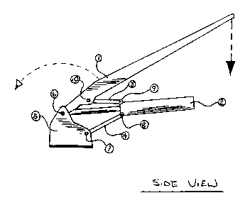
Figure 1 is a side view of an embodiment.
Figure 2 is a perspective view of the lifting device
Referring to the drawings, the embodiment of the invention
shown, a lifting device comprises a lifting arm 1 a hydraulic
cylinder 2, An upper link 3 and a lower link 4 and a mounting
frame or base 5. The arm is connected to the mounting frame
using a pin 6 allowing the arm free rotation. The hydraulic
cylinder is concurrent with the arm and is also connected
through pin 6 and is also allowed to rotate however independent
of the arm. One end of the lower link is attached to the
mounting frame using pin 7 while the other end is pinned to the
head of the hydraulic cylinder using pin 8 the upper link is
connected to the hydraulic cylinder through pin 9 while the
other end is pinned to the arm using pin 10. Two of these
structures mounted side by side and connected through a
horizontal member 11 at the ends of the arms, provides a means
to lift materials ( when suspended from the horizontal member)
from one position to another. To further enhance the capability
of this device a winch 12 is mounted on the horizontal member of
the ridged frame. The winch allows the load to be raised and
lowered to allow precise positioning of the load as it is placed
in the back of the mobile platform. A feature of this set-up and
due to the linkage arrangement is it's ability to potentially
rotate 180 degrees. When mounted on the back of a mobile
platform i.e. truck bed. The device has the ability to lift and
transfer material from behind the truck up and onto the truck
bed. And vice versa.
Although only a single embodiment of the present invention has
been described and illustrated, the present invention is not
limited to the features of this embodiment, but includes all
variations and modifications with
-3-

Representative Drawing
A single figure which represents the drawing illustrating the invention.
Administrative Status

2024-08-01:As part of the Next Generation Patents (NGP) transition, the Canadian Patents Database (CPD) now contains a more detailed Event History, which replicates the Event Log of our new back-office solution.

Please note that "Inactive:" events refers to events no longer in use in our new back-office solution.

For a clearer understanding of the status of the application/patent presented on this page, the site Disclaimer , as well as the definitions for Patent , Event History , Maintenance Fee  and Payment History  should be consulted.

Event History

Description Date
Time Limit for Reversal Expired 2007-07-10
Application Not Reinstated by Deadline 2007-07-10
Inactive: <RFE date> RFE removed 2007-05-11
Inactive: Adhoc Request Documented 2007-04-12
Request for Examination Received 2006-07-12
Inactive: Abandon-RFE+Late fee unpaid-Correspondence sent 2006-07-10
Deemed Abandoned - Failure to Respond to Maintenance Fee Notice 2006-07-10
Inactive: IPC from MCD 2006-03-12
Letter Sent 2005-05-30
Reinstatement Requirements Deemed Compliant for All Abandonment Reasons 2005-05-16
Inactive: Adhoc Request Documented 2005-04-13
Inactive: Office letter 2004-10-08
Deemed Abandoned - Failure to Respond to Maintenance Fee Notice 2004-07-12
Application Published (Open to Public Inspection) 2003-01-10
Inactive: Cover page published 2003-01-09
Inactive: First IPC assigned 2001-09-13
Inactive: Office letter 2001-08-28
Inactive: Inventor deleted 2001-08-21
Filing Requirements Determined Compliant 2001-08-21
Inactive: Filing certificate - No RFE (English) 2001-08-21
Inactive: Applicant deleted 2001-08-21
Application Received - Regular National 2001-08-21

Abandonment History

Abandonment Date Reason Reinstatement Date
2006-07-10
2004-07-12

Maintenance Fee

The last payment was received on 2005-05-16

Note : If the full payment has not been received on or before the date indicated, a further fee may be required which may be one of the following

  • the reinstatement fee;
  • the late payment fee; or
  • additional fee to reverse deemed expiry.

Patent fees are adjusted on the 1st of January every year. The amounts above are the current amounts if received by December 31 of the current year.
Please refer to the CIPO Patent Fees web page to see all current fee amounts.

Fee History

Fee Type Anniversary Year Due Date Paid Date
Application fee - small 2001-07-10
MF (application, 2nd anniv.) - small 02 2003-07-10 2003-05-20
MF (application, 3rd anniv.) - small 03 2004-07-12 2004-09-21
MF (application, 4th anniv.) - small 04 2005-07-11 2005-05-16
Reinstatement 2005-05-16
Owners on Record

Note: Records showing the ownership history in alphabetical order.

Current Owners on Record
DEAN W. SHAW
Past Owners on Record
None
Past Owners that do not appear in the "Owners on Record" listing will appear in other documentation within the application.
Documents

To view selected files, please enter reCAPTCHA code :


To view images, click a link in the Document Description column. To download the documents, select one or more checkboxes in the first column and then click the "Download Selected in PDF format (Zip Archive)" or the "Download Selected as Single PDF" button.

List of published and non-published patent-specific documents on the CPD .

If you have any difficulty accessing content, you can call the Client Service Centre at 1-866-997-1936 or send them an e-mail at CIPO Client Service Centre.


Document
Description 
Date
(yyyy-mm-dd) 
Number of pages   Size of Image (KB) 
Representative drawing 2002-06-10 1 7
Description 2001-07-09 3 138
Abstract 2001-07-09 1 26
Drawings 2001-07-09 1 19
Claims 2001-07-09 1 10
Filing Certificate (English) 2001-08-20 1 175
Notice: Maintenance Fee Reminder 2003-04-13 1 115
Notice: Maintenance Fee Reminder 2004-04-13 1 118
Courtesy - Abandonment Letter (Maintenance Fee) 2004-09-06 1 178
Second Notice: Maintenance Fee Reminder 2005-01-10 1 117
Notice: Maintenance Fee Reminder 2005-04-11 1 119
Notice of Reinstatement 2005-05-29 1 164
Reminder - Request for Examination 2006-03-12 1 117
Notice: Maintenance Fee Reminder 2006-04-10 1 128
Courtesy - Abandonment Letter (Request for Examination) 2006-08-20 1 167
Courtesy - Abandonment Letter (Maintenance Fee) 2006-09-04 1 175
Second Notice: Maintenance Fee Reminder 2007-01-10 1 125
Notice: Maintenance Fee Reminder 2007-04-10 1 118
Correspondence 2001-08-20 1 12
Fees 2003-05-19 2 93
Correspondence 2004-10-07 1 20
Fees 2004-09-20 1 72
Fees 2005-05-15 1 54