Language selection

Search

Patent 2354345 Summary

Third-party information liability

Some of the information on this Web page has been provided by external sources. The Government of Canada is not responsible for the accuracy, reliability or currency of the information supplied by external sources. Users wishing to rely upon this information should consult directly with the source of the information. Content provided by external sources is not subject to official languages, privacy and accessibility requirements.

Claims and Abstract availability

Any discrepancies in the text and image of the Claims and Abstract are due to differing posting times. Text of the Claims and Abstract are posted:

  • At the time the application is open to public inspection;
  • At the time of issue of the patent (grant).
(12) Patent Application: (11) CA 2354345
(54) English Title: FLOATING PUNCH-HOLDER
(54) French Title: PORTE-POINCON FLOTTANT
Status: Deemed Abandoned and Beyond the Period of Reinstatement - Pending Response to Notice of Disregarded Communication
Bibliographic Data
(51) International Patent Classification (IPC):
  • B26D 7/00 (2006.01)
  • B21D 28/00 (2006.01)
  • B21D 28/34 (2006.01)
  • B26D 7/26 (2006.01)
  • B26F 1/00 (2006.01)
(72) Inventors :
  • TALARICO, JOHN (Canada)
(73) Owners :
  • V. SCHWARTZMANN
(71) Applicants :
  • V. SCHWARTZMANN (United States of America)
(74) Agent:
(74) Associate agent:
(45) Issued:
(22) Filed Date: 2001-07-19
(41) Open to Public Inspection: 2003-01-19
Availability of licence: N/A
Dedicated to the Public: N/A
(25) Language of filing: English

Patent Cooperation Treaty (PCT): No

(30) Application Priority Data: None

Abstracts

English Abstract


An improved floating punch-holder for a punching apparatus comprising an
assembly of a chuck
having an upper portion and a lower portion. The upper portion of the chuck is
provided to be
securely attached to the punching apparatus. The chuck is provided to hold a
shank having an upper
portion and a lower portion, the upper portion of the shank being held by the
chuck and the lower
portion of said shank is connected to a punch. The punch is adapted to
cooperate with a die located
below the punch and centred with the punch. A centring assembly is adapted to
accommodate the
upper portion of the shank and is provided to facilitate a precise alignment
and centring of the punch
with the die. Centring assembly is detachably mounted to the lower portion of
the chuck and is
adapted to retain the position of the shank centred, even when the shank is
removed for servicing.
A locking assembly is adapted to immobily lock the upper portion of the shank
to the lower portion
of the chuck.


Claims

Note: Claims are shown in the official language in which they were submitted.

5
CLAIMS:
1. Floating punch-holder for a punching apparatus comprising an assembly of:
a chuck having an upper portion and a lower portion, the upper portion of said
chuck is provided
to be securely attached to the punching apparatus, said chuck is provided to
hold
a shank having an upper portion and a lower portion, the upper portion of said
shank being held
by said chuck and the lower portion of said shank is connected to
a punch, said punch is adapted to cooperate with
a die located below the punch and centred with said punch;
a centring means adapted to accommodate the upper portion of said shank, said
centring means
are provided to facilitate a precise alignment and centring of said punch with
said die;
wherein said centring means are detachably mounted to the lower portion of
said chuck, and
wherein said centring means are adapted to retain the position of said shank
centred even when said
shank is removed for servicing;
a locking means adapted to immobily lock the upper portion of said shank to
the lower portion
of said chuck.
2. Floating punch-holder according to claim 1, wherein said centring means are
adapted to
accommodate the upper portion of said shank in a slide-fit manner.
3. Floating punch-holder according to claim 2, wherein said centring means
comprises a locating ring,
and wherein the upper portion of said shank having a cylindrical
configurations, wherein an inner
diameter of said locating ring fits precisely with a close tolerance within
the upper portion of said
shank.
4. Floating punch-holder according to claim 3, wherein said locating ring is
detachably mounted to
the lower portion of said chuck by an inner clamp, wherein said locating ring
is adapted to move
within said inner clamp in lateral directions necessary for precise alignment
and centring of said punch
with said die.

6
5. Floating punch-holder according to claim 4, wherein said inner clamp is
detachably mounted to
lower portion of said chuck by tightening means.
6. Floating punch-holder according to claim 4, wherein said locking means
comprises an outer clamp,
said outer clamp is detachably mounted to the lower portion of said chuck by
tightening means.
7. Floating punch-holder according to claim 6, wherein said inner clamp is
provided with a number
of counter-bore holes formed in said inner clamp, wherein said counter-bore
holes allow said outer
clamp to be locked directly to the lower portion of said chuck.

Description

Note: Descriptions are shown in the official language in which they were submitted.


CA 02354345 2001-07-19
FLOATING PUNCH HOLDER
This application is an improvement of the US patent 5,992,285 to Joe Talarico.
The present invention relates to an apparatus for wing a punch onto a machine
such as a
punch press, more particularly to a floating punch-holder, and provide the
means to align the punch
within the punch-holder with a corresponding hole in a die set on the bed or
horn of the aforesaid
machine to avoid the need of using a specialised machine or die set.
There is known US patent 5,992,285 to Joe Talarico comprising a floating punch-
holder
provided with a chuck having within its lower portion an open-ended cavity to
accommodate an
upper portion of a shank connected to a punch. In this arrangement, the
process of centering and
alignment of the upper portion of the shank was performed by means of using
sets of screws provided
to adjust the shank's upper portion within the cavity by means of advance
movement of said screws
causing lateral movement of the upper portion of the shank.
Such an arrangement, even though it is very precise, necessitates all steps of
alignment and
centering of the shank each time the shank is removed for servicing.
The present improvement eliminates the described disadvantage and comprises an
improved
configuration of the centering assembly capable to keep the position of the
shank "centered" even
when the shank is removed for servicing.
SUMMARY OF THE INVENTION
The primary objective of the present invention is to provide a floating punch-
holder having
a centereing means provided to facilitate a precise alignment and centering of
the punch with the die

CA 02354345 2001-07-19
2
in such a way that those centering means are adapted to retain the position of
the shank centered even
when the shank is removed for servicing.
The second objective ofthe present invention is to provide a floating punch
holder of the type
descn'bed above wherein the cenreting means comprises a locating ring and
wherein the upper portion
ofthe shank has a cylindrical configuration where an inner diameter of the
locating ring fits precisely
with a close tolerance within the upper portion of the shank.
The third objective of the present invention is to provide a floating punch
holder of the type
described above wherein the upper portion of the shank is locked to the lower
portion of the chuck
by a locking means comprising an outer clamp which is detachably mounted to
the lower portion of
the chuck by tightening means.
BRIEF DESCRIPTION OF THE DRAWINGS
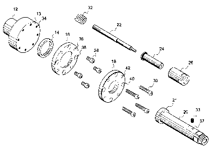
Fig. 1. shows a perspective view of the dis-assembled floating punch-holder
according to the present
invention.
Fig. 2 shows a side cross-section of the assembled punch-holder of Fig. 1.
Fig. 3 is a side cross-sectional view of a die assembly.
DETAILED DESCRIPTION OF THE PRESENT INVENTION
Referring now to drawings, Figs 1 and 2 show a floating punch-holder 10
comprising a chuck
12 having a shape of a stub provided for fastening into a ram (not shown). The
lower portion 13 of
the chuck 12 has a number of bore holes 34. Centering means or assembly
comprises a locating ring
14 adapted to be held in place by means of an inner clamp 16 provided to be
tightened to the chuck
12 by means of a set of screws 28. The locating ring 14 is adapted to move in
lateral directions within
the inner clamp 16 due to the fact that the outer diameter of the locating
ring 14 is smaller than the
inner diameter of the inner clamp 16. A shank 20 having an upper portion 21 of
a cylindrical
configuration is adapted to be accommodated within the locating ring 14. The
inner diameter of the
locating ring 14 has precise dimensions adapted to fit with close tolerance
within the upper portion
21 of the shank 20, thus providing an accurate location and close tolerance of
the upper portion of
the shank in a slide-fit manner during centering and alignment. The shank 20
is held in place by means

CA 02354345 2001-07-19
3
of an outer clamp 18 provided with bore holes 42. The outer clamp 18 is
attached to the lower
portion 13 of chuck 12 by means of a set of screws 30 and can be tightened
into the corresponding
bores 34 of chuck 12 completely independently from the centering assembly.
This arrangement is
achieved by means ofusing counter-bore holes 38 formed in the inner clamp 16
and allowing screws
30 holding outer clamp 18 to pass right through the inner clamp 16 to be
attached directly to the
chuck 12. This independency of attachment is a very important feature of the
present invention. Due
to the fact that the height or thickness of the upper portion of the shank 20
is greater than the height
or thickness ofthe locating ring 14, outer clamp 18 will tightly hold only the
upper portion 21 of the
shank 20 without affecting the functioning of inner clamp 16 provided to hold
the locating ring 14.
Clearance holes 40 are formed on the outer clamp 18 to facilitate the access
to screws 28 tightening
the inner clamp 16.
The lower portion of the shank 20 is provided with a bore 23 for holding a
punch 22 by means
of a set screw 35 to be inserted within the corresponding bore hole 37 formed
within the shank 20.
The punch-holder further includes a spring holder 26, crown 24 and a spring
32. A tip 46 of the
punch 22 is adapted to cooperate with a die 48 of Fig. 3 to perform a punching
process.
In operation, the centering assembly comprising the locating ring 14 and inner
clamp 16 is
attached to the chuck 12 without complete tightening of screws 28. Further,
shank 20 is placed within
the locating ring 14 and attached to the chuck 12 by means of the outer clamp
18 without complete
tightening of screws 30. In this case, screws 30 are inserted into the
corresponding bore holes 34
formed in the lower portion 13 of the chuck 12 via counter-bore holes 38 of
the inner clamp 16.
During the alignment and centering, the upper portion 21 of the shank 20 is
adjusted by lateral
movement of the shank-ring assembly within the inner clamp 16. Once the
assembly is aligned and
tested on the machine, screws 28 holding the inner clamp 16 are completely
tightened by means of
accessing those screws through clearance holes 40 formed in the outer clamp 18
holding the upper
portion 21 of the shank 20. As the result, the locating ring 14, which is held
in place by means of the
inner clamp 16, will retain the position of the shank "centered" even when the
shank 20 is removed
for servicing. For removing the shank for servicing, it is necessary to simply
loosen screws 30 and
to remove the outer clamp 18. During re-assembly, the shank 20 will be placed
within the locating
ring 14 exactly in the same position as it was when the centering was done.
Such feature of the

CA 02354345 2001-07-19
4
present invention permits easy removal of the shank and quick re-assembly
without re-aligning of the
punch assembly each time.
The fact that chuck 12 is the only holding device to hold both inner clamp 16
and outer clamp
18 makes such punch-holder assembly of the present invention very simple to
handle.
Thus, it can be seen that the objects of the present invention have been
satisfied by the
structure presented hereinabove. While in accordance with the Patent Statutes,
only the best mode
and preferred embodiments of the present invention have been presented and
described in detail, it
is to be understood that the invention is not limited thereto or thereby.
Accordingly, for an
appreciation of the true scope and breadth of the invention, references should
be made to the
following claims.

Representative Drawing
A single figure which represents the drawing illustrating the invention.
Administrative Status

2024-08-01:As part of the Next Generation Patents (NGP) transition, the Canadian Patents Database (CPD) now contains a more detailed Event History, which replicates the Event Log of our new back-office solution.

Please note that "Inactive:" events refers to events no longer in use in our new back-office solution.

For a clearer understanding of the status of the application/patent presented on this page, the site Disclaimer , as well as the definitions for Patent , Event History , Maintenance Fee  and Payment History  should be consulted.

Event History

Description Date
Revocation of Agent Requirements Determined Compliant 2023-03-07
Application Not Reinstated by Deadline 2006-07-19
Time Limit for Reversal Expired 2006-07-19
Inactive: IPC from MCD 2006-03-12
Deemed Abandoned - Failure to Respond to Maintenance Fee Notice 2005-07-19
Inactive: IPC assigned 2003-08-20
Letter Sent 2003-07-09
Inactive: Correspondence - Transfer 2003-05-07
Inactive: Office letter 2003-04-09
Inactive: Cover page published 2003-01-19
Application Published (Open to Public Inspection) 2003-01-19
Inactive: Applicant deleted 2002-02-06
Inactive: Office letter 2002-02-06
Inactive: Inventor deleted 2002-02-06
Inactive: Correspondence - Formalities 2001-10-29
Inactive: Filing certificate correction 2001-10-29
Inactive: First IPC assigned 2001-10-19
Inactive: Filing certificate - No RFE (English) 2001-08-24
Filing Requirements Determined Compliant 2001-08-24
Application Received - Regular National 2001-08-24

Abandonment History

Abandonment Date Reason Reinstatement Date
2005-07-19

Maintenance Fee

The last payment was received on 2004-07-14

Note : If the full payment has not been received on or before the date indicated, a further fee may be required which may be one of the following

  • the reinstatement fee;
  • the late payment fee; or
  • additional fee to reverse deemed expiry.

Please refer to the CIPO Patent Fees web page to see all current fee amounts.

Fee History

Fee Type Anniversary Year Due Date Paid Date
Application fee - small 2001-07-19
Registration of a document 2003-02-11
MF (application, 2nd anniv.) - small 02 2003-07-21 2003-07-15
MF (application, 3rd anniv.) - small 03 2004-07-19 2004-07-14
Owners on Record

Note: Records showing the ownership history in alphabetical order.

Current Owners on Record
V. SCHWARTZMANN
Past Owners on Record
JOHN TALARICO
Past Owners that do not appear in the "Owners on Record" listing will appear in other documentation within the application.
Documents

To view selected files, please enter reCAPTCHA code :


To view images, click a link in the Document Description column. To download the documents, select one or more checkboxes in the first column and then click the "Download Selected in PDF format (Zip Archive)" or the "Download Selected as Single PDF" button.

List of published and non-published patent-specific documents on the CPD .

If you have any difficulty accessing content, you can call the Client Service Centre at 1-866-997-1936 or send them an e-mail at CIPO Client Service Centre.


Document
Description 
Date
(yyyy-mm-dd) 
Number of pages   Size of Image (KB) 
Representative drawing 2002-03-06 1 13
Cover Page 2002-12-30 1 45
Description 2001-07-19 4 175
Drawings 2001-07-19 2 39
Abstract 2001-07-19 1 24
Claims 2001-07-19 2 60
Filing Certificate (English) 2001-08-24 1 175
Reminder of maintenance fee due 2003-03-20 1 106
Courtesy - Certificate of registration (related document(s)) 2003-07-09 1 105
Courtesy - Abandonment Letter (Maintenance Fee) 2005-09-13 1 173
Reminder - Request for Examination 2006-03-21 1 125
Correspondence 2001-10-29 2 69
Correspondence 2002-02-06 1 9
Correspondence 2003-04-09 1 19
Fees 2003-07-15 2 62
Fees 2004-07-14 1 32