Language selection

Search

Patent 2354485 Summary

Third-party information liability

Some of the information on this Web page has been provided by external sources. The Government of Canada is not responsible for the accuracy, reliability or currency of the information supplied by external sources. Users wishing to rely upon this information should consult directly with the source of the information. Content provided by external sources is not subject to official languages, privacy and accessibility requirements.

Claims and Abstract availability

Any discrepancies in the text and image of the Claims and Abstract are due to differing posting times. Text of the Claims and Abstract are posted:

  • At the time the application is open to public inspection;
  • At the time of issue of the patent (grant).
(12) Patent: (11) CA 2354485
(54) English Title: PAVING SCREED FOR A PAVER
(54) French Title: POUTRE LISSEUSE DE BITUME ROUTIER POUR FINISSEUSE
Status: Expired and beyond the Period of Reversal
Bibliographic Data
(51) International Patent Classification (IPC):
  • E01C 19/22 (2006.01)
  • E01C 19/42 (2006.01)
(72) Inventors :
  • ROWER, HELMUT (Germany)
(73) Owners :
  • ABG ALLGEMEINE BAUMASCHINEN-GESELLSCHAFT MBH
(71) Applicants :
  • ABG ALLGEMEINE BAUMASCHINEN-GESELLSCHAFT MBH (Germany)
(74) Agent: PERRY + CURRIER
(74) Associate agent:
(45) Issued: 2010-02-02
(22) Filed Date: 2001-07-27
(41) Open to Public Inspection: 2002-01-28
Examination requested: 2006-06-08
Availability of licence: N/A
Dedicated to the Public: N/A
(25) Language of filing: English

Patent Cooperation Treaty (PCT): No

(30) Application Priority Data:
Application No. Country/Territory Date
10036784.4 (Germany) 2000-07-28

Abstracts

English Abstract

The invention relates to a paving screed for a paver, with a basic screed and with at least one lateral extendable screed part which is connected to the basic screed via hydraulically actuable tensioners and the height of which can be adjusted by means of a height setting device which comprises vertical spindles which are coupled to the extendable screed part and are held on the basic screed rotatably relative to the latter, the spindles being adjustable via a common drive motor, it being possible, as a result of the actuation of the drive motor, to trigger a release of the hydraulically actuable tensioners for the duration of actuation and the extendable screed part. being additionally connected to the basic screed via spring-biased screws.


French Abstract

L'invention concerne une poutre lisseuse de bitume routier pour finisseuse, composée d'une poutre lisseuse de base et d'au moins une partie de poutre lisseuse extensible latérale qui est reliée à la poutre lisseuse de base par l'intermédiaire de tendeurs actionnables hydrauliquement et dont la hauteur peut être réglée au moyen d'un dispositif de réglage de hauteur qui comprend des broches verticales qui sont couplées à la partie extensible de la poutre lisseuse et qui sont maintenues sur la poutre lisseuse de base de façon rotative par rapport à celle-ci, les broches étant réglables par l'intermédiaire d'un moteur d'entraînement commun, ce qui est possible grâce à l'actionnement du moteur d'entraînement, pour faire dégager les tendeurs actionnables hydrauliquement durant la durée d'actionnement et la partie extensible de la poutre lisseuse étant en outre reliée à la poutre lisseuse de base par l'intermédiaire de vis à ressort.

Claims

Note: Claims are shown in the official language in which they were submitted.

7
What we claim is:
1. A paving screed for a paver, with a basic screed and with at least
one lateral extendable screed part which is connected to the basic
screed via hydraulically actuable tensioners and the height of which
can be adjusted by means of a height setting device, the height
setting device comprising vertical spindles which are coupled to the
extendable screed part and which are held on the basic screed
rotatably relative thereto, the spindles being adjustable via a
common drive motor, it being possible, as a result of the actuation of
the drive motor, to trigger a release of the hydraulically actuable
tensioners for the duration of actuation and the extendable screed
part being additionally connected to the basic screed via spring-
biased screws.
2. The paving screed of Claim 1, wherein the spindles are driven by the drive
motor via a common shaft.
3. The paving screed of Claim 2, wherein the shaft consists of two part-
shafts mounted on respective end faces and coupled to one
another.
4. The paving screed of Claim 1, wherein the spring-biased screws are
provided with self-locking nuts:
5. The paving screed of Claim 1, wherein the spindles are driven via worm
gears.
6. The paving screed of Claim 1, wherein the hydraulically actuable
tensioners each have a shank which is screwed to the extendable

8
screed part and which carries a piston which is spring-biased
against a surrounding cylinder housing and can be subjected to
hydraulic pressure counter to the spring bias.
7. The paving screed of Claim 6, wherein the tensioners are guided in
long holes on the basic screed via guide discs.
8. The paving screed of Claim 1, wherein the spindle of an individual
extendable screed part is adjustable.

Description

Note: Descriptions are shown in the official language in which they were submitted.


CA 02354485 2009-03-12
1
Paving screed for a paver
FIELD OF THE INVENTION
The invention relates to a paving screed for a paver used for road
constructions and provided with a floating screed.
BACKGROUND OF THE INVENTION
In the case of payers which are provided with a chassis and with a
trailed floating paving screed which is articulated on the later via tension
1o arms and of which the setting angle relative to the ground can be set via
actuating cylinders and which comprises at least one ground-facing screed
board, mix is introduced via a front hopper, is conveyed by means of a
conveyer into the region in front of the paving screed and is distributed
there over the width of the paving screed by means of a distributor auger,
in order then to be paved by means of the paving screed.
For larger paving widths, a basic screed of the paving screed can be
widened by extendable screed parts being extended and/or by screed
lengthening parts being attached to the extendable screed part. It is known
in this context that the extendable screed parts are manually adjustable in
terms of their height with respect to the basic screed by means of spindles.
However, this is complicated and time-consuming.
SUMMARY OF THE INVENTION
An object of an aspect of the invention is to provide a paving screed
with a possibility to adjust extendable screed parts in terms of their height
relative to the basic screed in a convenient way.
According to an aspect of the invention, spindles for adjusting the
height of extendable screed parts are adjustable via a common drive

CA 02354485 2009-03-12
2
motor, the actuation of the drive motor being able to release automatically
for the duration of actuation hydraulically actuable tensioners via which the
extendable screed is connected to the basic screed, whilst the extendable
screed part is additionally connected to the basic screed via spring-biased
screws, in such a way that it becomes possible for the height of the
extendable screed part to be adjusted relative to the basic screed, but a
clamping force is nevertheless exerted between these. Any play of the
spindles, which could cause the spindle to swing, does not occur as a
result. The hydraulically actuable tensioners are automatically tensioned
again by terminating the actuation of the drive motor.
Further embodiments, advantages and objects of the invention will
become apparent from the following description and from the claims.
BRIEF DESCRIPTION OF THE DRAWINGS
The invention is explained in more detail below with reference to an
exemplary embodiment illustrated diagrammatically in the accompanying
figures.
Fig. 1 shows a side view of a paver.
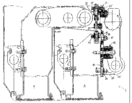
Fig. 2 shows diagrammatically, as a detail and partially in section,
the region of abutment between the basic screed and the screed
lengthening part.
Fig. 3 shows a top view of an embodiment of a drive for adjusting
the height of a screed lengthening part.
Fig. 4 shows diagrammatically a side view of a paving screed of a
paver with cheeks for extension cylinders and guide rods.

CA 02354485 2009-03-12
3
DETAILED DESCRIPTION OF A PREFERRED EMBODIMENT
The paver illustrated in Fig. I comprises a chassis 1 with a crawler
track assembly 2(wheel mechanisms may also be provided instead), the
chassis I having at the front a hopper 3 and at the rear a distributor auger
4, between which a conveyer (which cannot be seen) is arranged for
transporting mix to be paved out of the hopper 3 through a conveying shaft,
above which superstructures are located, into the region of the distributor
auger 4.
A floating paving screed 5 for the floating paving of the mix to be
1o paved is articulated on the chassis I via tension arms 6. The paving screed
is located behind the region of the distributor auger 4 in the paving
direction and may comp(se a basic screed 7, if appropriate with
extendable screeds 8 extendable laterally and independently of one
another. The basic screed 7 is divided centrally in the conventional way,
the two halves of the basic screed 7 being capable of being inclined
relative to one another in order to set a roof profile transversely to the
paving direction. The basic screed 7 can be widened to approximately
double its width by means of the extendable screeds 8. If additional
widening is also to be carried out, this is brought about by additional screed
lengthening parts not illustrated in Fig. 1), which are capable of being
attached manually to the extendable screeds 8. The extendable screeds 8
are generally offset relative to the basic screed 7 by a screed depth A, as
seen in the paving direction.
Each tension arm 6 is articulated pivotably at its front end on the
chassis 1, the height of the articulation point being capable of being
adjusted relative to the chassis I.
As is evident from Fig. 2, an extendable screed part 8 is arranged
adjacently to a cheek 10 of the basic screed 7, the cheek 10 having long

CA 02354485 2009-03-12
4
holes 11 which serve for leading through hydraulically actuable tensioners
12, cf. for example, also U.S. Patent 6,190,087 B1.
The hydraulically actuable tensioners 12 each possess a shank 14
provided on the end face with a thread 13, the thread 13 being in
engagement with a corresponding threaded bore in the extendable screed
part 8. Seated on the shank 14 is a piston 16 which comprises a guide
sleeve 15 and which is arranged movably and in an appropriately sealed
off manner within a cylinder housing 17. The cylinder housing 17
possesses, adjacent to the cheek 10, a bottom 18 with a bore 19, through
which the shank 14 extends and into it the guide sleeve 15 extends. On the
side opposite the bottom 18, the cylinder housing 17 is closed by means of
a cover 20, through which the shank 14 and the guide sleeve 15 likewise
extend. Between the piston 16 and the bottom 18 is arranged a cup-spring
assembly 21 which biases the cylinder housing 17 relative to the piston 16.
Hydraulic fluid can be introduced into the region between the piston
16 and the cover 20 via a bore 22 in the cover 20, in order to counteract the
biascaused by the cup-spring assembly 21. The guide sleeve 15 comes to
bear, on the side facing away from the bottom 18, against a self-locking nut
23 screwed onto the shank 14.
Without being subjected to pressure, the cup-spring assembly 21
tensions the cylinder housing 17 and, consequently, the extendable screed
part 8 against the cheek 10. If, by contrast, the interspace between the
piston 16 and the cover 20 is subjected to pressure, the cylinder housing
17 moves relative to the piston 16 and, consequently, to the shank 14, the
cup-spring assembly 21 being compressed at the same time, so that the
bias between the cheek 10 and the extendable screed part 8 is cancelled.
In addition, the extendable screed part 8 is connected to the cheek
10 by means of screws 25 which are biased by means of cup-springs 24

CA 02354485 2009-03-12
4a
and the shanks of which are likewise led through long holes 26 in the
cheek 10 and are screwed to the extendable screed part 8. The screws 25
are supported on the cheek 10 via washers 27 and expediently carry a self-
locking nut 28.
Fastened to the basic screed 7 are two threaded bushes 29, through
which extend vertically arranged spindles 30 provided with a thread. The
spindles 30 are received rotatably at their lower end by a lug 31 fastened to
the extendable screed part 8. By the spindles 30 being rotated, therefore,
the height of the extendable screed part 8 can be adjusted relative to the
basic screed 7.
The height adjustment of the extendable screed part 8 takes place
via a preferably hydraulic drive motor 32, for example, a geared motor,
which is connected to an output shaft 34 via a clutch 33. The output shaft

CA 02354485 2001-07-27
- 5 -
34 carries two worms 35, which are in engagement with corresponding
worm wheels 36. The worm wheels 36 are in each case located on a shaft
37 which is mounted on the basic screed 7 via bearings 37 and which is in
engagement with a respective spindle 30.
The shaft 34 expediently consists of two part-shafts 34', 34" which
are in each case niounted on the two sides of the associated worm 35 by
means of bearings 37' and are coupled to one another via a coupling 38.
A clutch housing 39 is provided ana, in the exemplary embodiment
illustrated, possesses an internally toothed clutch sleeve 40 which is in
engagement, on the one hand, with a motor-side pinion 41 and, on the
other hand, with a shaft-side pinion 42, in order to ensure a suitable
connection.
When the drive motor 32 is actuated via a switch or the like (not
illustrated), the switching of a valve (not illustrated) triggered thereby
causes the hydraulic tensioners 12 to be subjected to hydraulic fluid and
thereby released, whilst the screws 25 continue to brace the extendable
screed part 8 together with the cheek 10. The height, and therefore also
the inclination, of the extendable screed part 8 relative to the basic screed
7 can then be adjusted via the drive motor 32 as a result of the rotation of
the spindles 30 which is brought about thereby, the spring bias of the
screws 25 allowing this, but having the effect that the extendable screed
part 8 is kept in bearing contact against the cheek 10. When the actuation
of the drive motor 32 is terminated, the valve (not illustrated) for hydraulic
fluid is changed over again, so that the tensioners 12 are no longer
subjected to pressure and therefore once again brace the extendable
screed part 8 against the cheek 10 in the now adjusted position.
The drive motor 32 can also be activated for the purpose of height
adjustment by an appropriate controller, in which case this can then be
dependent on the travel of the paver and therefore on the paving position
or on the measured values from corresponding sensors.

CA 02354485 2001-07-27
- 6 -
The respective shank 14 expediently carries an essentially
rectangular guide disc 43 which is vertically movable in the long hole 11
and which ensures lateral positioning between the extendable screed part
8 and the basic screed 7. This may, however, also be ensured by keyhole-
like orifices in the cheek 10, instead of the long holes 11, when the width of
the lower, narrow portion of these orifices corresponds essentially to the
diameter of the shank 14.
It is also at the same time possible in a simple way to adjust only
one spindle 30 of an extendable screed part 8 for the trimming of the latter,
by screws 38' of the coupling 38 being released.
It will be appreciated by those skilled in the art that changes could
be made to the embodiment described above without departing from the
broad - inventive concept thereof. It is understood, therefore, that this
invention is not limited to the particular embodiment disclosed, but it is
intended to cover modifications within the spirit and scope of the present
invention as defined by the appended claims.

Representative Drawing
A single figure which represents the drawing illustrating the invention.
Administrative Status

2024-08-01:As part of the Next Generation Patents (NGP) transition, the Canadian Patents Database (CPD) now contains a more detailed Event History, which replicates the Event Log of our new back-office solution.

Please note that "Inactive:" events refers to events no longer in use in our new back-office solution.

For a clearer understanding of the status of the application/patent presented on this page, the site Disclaimer , as well as the definitions for Patent , Event History , Maintenance Fee  and Payment History  should be consulted.

Event History

Description Date
Time Limit for Reversal Expired 2019-07-29
Letter Sent 2018-07-27
Grant by Issuance 2010-02-02
Inactive: Cover page published 2010-02-01
Inactive: Final fee received 2009-11-05
Pre-grant 2009-11-05
Notice of Allowance is Issued 2009-07-20
Letter Sent 2009-07-20
Notice of Allowance is Issued 2009-07-20
Inactive: Approved for allowance (AFA) 2009-07-14
Amendment Received - Voluntary Amendment 2009-03-12
Inactive: S.30(2) Rules - Examiner requisition 2008-09-23
Amendment Received - Voluntary Amendment 2006-11-23
Letter Sent 2006-07-11
Request for Examination Received 2006-06-08
All Requirements for Examination Determined Compliant 2006-06-08
Request for Examination Requirements Determined Compliant 2006-06-08
Inactive: IPC from MCD 2006-03-12
Appointment of Agent Requirements Determined Compliant 2005-09-12
Inactive: Office letter 2005-09-12
Revocation of Agent Requirements Determined Compliant 2005-09-12
Appointment of Agent Request 2005-08-12
Inactive: Correspondence - Formalities 2005-08-12
Revocation of Agent Request 2005-08-12
Inactive: Cover page published 2002-02-04
Application Published (Open to Public Inspection) 2002-01-28
Letter Sent 2001-11-08
Inactive: Single transfer 2001-10-03
Inactive: First IPC assigned 2001-09-28
Inactive: Courtesy letter - Evidence 2001-08-28
Filing Requirements Determined Compliant 2001-08-24
Inactive: Filing certificate - No RFE (English) 2001-08-24
Application Received - Regular National 2001-08-24

Abandonment History

There is no abandonment history.

Maintenance Fee

The last payment was received on 2009-06-15

Note : If the full payment has not been received on or before the date indicated, a further fee may be required which may be one of the following

  • the reinstatement fee;
  • the late payment fee; or
  • additional fee to reverse deemed expiry.

Please refer to the CIPO Patent Fees web page to see all current fee amounts.

Owners on Record

Note: Records showing the ownership history in alphabetical order.

Current Owners on Record
ABG ALLGEMEINE BAUMASCHINEN-GESELLSCHAFT MBH
Past Owners on Record
HELMUT ROWER
Past Owners that do not appear in the "Owners on Record" listing will appear in other documentation within the application.
Documents

To view selected files, please enter reCAPTCHA code :


To view images, click a link in the Document Description column. To download the documents, select one or more checkboxes in the first column and then click the "Download Selected in PDF format (Zip Archive)" or the "Download Selected as Single PDF" button.

List of published and non-published patent-specific documents on the CPD .

If you have any difficulty accessing content, you can call the Client Service Centre at 1-866-997-1936 or send them an e-mail at CIPO Client Service Centre.


Document
Description 
Date
(yyyy-mm-dd) 
Number of pages   Size of Image (KB) 
Representative drawing 2002-01-02 1 69
Drawings 2001-07-27 4 495
Abstract 2001-07-27 1 24
Description 2001-07-27 6 305
Claims 2001-07-27 2 54
Cover Page 2002-02-04 1 99
Description 2009-03-12 7 284
Claims 2009-03-12 2 43
Drawings 2009-03-12 4 366
Representative drawing 2010-01-08 1 78
Cover Page 2010-01-08 2 112
Filing Certificate (English) 2001-08-24 1 175
Courtesy - Certificate of registration (related document(s)) 2001-11-08 1 113
Reminder of maintenance fee due 2003-03-31 1 107
Reminder - Request for Examination 2006-03-28 1 125
Acknowledgement of Request for Examination 2006-07-11 1 176
Commissioner's Notice - Application Found Allowable 2009-07-20 1 161
Maintenance Fee Notice 2018-09-07 1 180
Correspondence 2001-08-24 1 24
Fees 2003-06-17 1 48
Fees 2004-06-29 1 45
Fees 2005-06-14 1 52
Correspondence 2005-08-12 2 56
Correspondence 2005-08-12 1 20
Correspondence 2005-09-12 1 17
Correspondence 2005-09-12 1 15
Fees 2006-06-23 1 36
Fees 2007-05-31 1 50
Fees 2008-06-26 1 51
Fees 2009-06-15 1 199
Correspondence 2009-11-05 1 38