Note: Descriptions are shown in the official language in which they were submitted.
CA 02354677 2001-08-03
DEVICES AND METHODS FOR PORT-ACCESS MULTIVESSEL
CORONARY ARTERY BYPASS SURGERY
CROSS-REFERENCES TO RELATED APPLICATIONS
The present application is a continuation of copending U.S. Patent Application
No. 09/487,024, filed January 19, 2000, which is a divisional of U.S. Patent
Application No.
08/486,941, filed June 7, 1995, now issued as U.S. Patent No. 5,799,661, which
is a
continuation-in-part of Application Serial No. Serial No. 08/281,891, filed
July 28, 1994, now
issued as U.S. Patent No. 5,735,290, which itself is a continuation-in-part of
copending U.S.
~o patent application Serial No. 08/023,778, filed February 22, 1993, now
issued as U.S. Patent
No. 5,452,733. The complete disclosures of these related U.S. patent
applications are hereby
incorporated herein by reference for all purposes
BACKGROUND OF THE INVENTION
Field of the Invention
~5 The present invention relates generally to devices and methods for
performing
thoracoscopic cardiac procedures. More particularly, the present invention
relates to devices
and methods for performing coronary artery bypass graft (CABG) surgery for
multivessel
coronary artery disease through port-access or closed-chest thoracoscopic
methods.
Background of the Invention
2o Coronary artery disease remains the leading cause of morbidity and
mortality
in Western societies. Coronary artery disease is manifested in a number of
ways. For
example, disease of the coronary arteries can lead to insufficient blood flow
resulting in the
discomfort and risks of angina and ischemia. In severe cases, acute blockage
of coronary
blood flow can result in myocardial infarction, leading to immediate death or
damage to the
25 myocardial tissue.
A number of approaches have been developed for treating coronary artery
disease. In less severe cases, it is often sufficient to treat the symptoms
with pharmaceuticals
and lifestyle modification to lessen the underlying causes of disease. In more
severe cases, the
coronary blockages) can often be treated endovascularly using techniques such
as balloon
3o angioplasty, atherectomy, laser ablation, stents, hot tip probes, and the
like.
CA 02354677 2001-08-03
In cases where pharmaceutical treatment and/or endovascular approaches have
failed or are likely to fail, it is often necessary to perform a coronary
artery bypass graft
procedure using open surgical techniques. Such techniques require that the
patient's sternum
be opened and the chest be spread apart to provide access to the heart. A
source of arterial
blood is then connected to a coronary artery downstream from an occlusion
while the patient
is maintained under cardioplegia and is supported by cardiopulmonary bypass.
The source of
blood is often the left or right internal mammary artery, and the target
coronary artery can be
the left anterior descending artery, circumflex artery, right coronary artery
or any one of their
branches which might be narrowed or occluded.
to While very effective in many cases, the use of open surgery to perform
coronary artery bypass grafting is highly traumatic to the patient. The
procedure requires
immediate postoperative care in an intensive care unit, a total period of
hospitalization of
seven to ten days, and a recovery period that can be as long as six to eight
weeks.
It would therefore be desirable to provide other, less traumatic methods and
15 techniques for performing coronary artery bypass grafting. It would be
particularly desirable if
such techniques did not require opening of the patient's sternum, and might be
even more
desirable if such techniques could be performed using thoracoscopic methods.
Such
thoracoscopic methods could decrease morbidity and mortality, cost, and
recovery time when
compared to conventional open surgical coronary bypass procedures. In
addition, such
2o methods could be even more efficacious than open-surgical bypass
procedures.
Copending U.S. patent application Serial No. 08/281,891 describes a method
of performing coronary bypass graft surgery for single vessel coronary artery
disease using
port-access or closed-chest thoracoscopic methods. However, of the over
365,000 open-chest
CABG operations performed in 1993, only 5-15% were for single vessel coronary
artery
25 disease. For the benefits of thoracoscopic CABG surgery to reach the
remainder of the patient
population, the procedure must be expanded to address multivessel disease.
Treatment of
multivessel coronary artery disease involves rerouting multiple conduits to
supply blood to
the blocked coronary arteries downstream of the blockages. Typical conduits
used for CABG
surgery in multivessel disease include arterial conduits, such as the left
internal mammary
3o artery (LIMA), the right internal mammary artery (RIMA) or the right
gastroepiploic artery
(RGEA), or venous conduits such as the greater saphenous vein (GSV) or the
lesser
saphenous vein (LSV). Often a combination of these and other conduits is
necessary to
achieve complete revascularization of the obstructed coronary arteries. Open-
chest
2
CA 02354677 2001-08-03
approaches to treatment of multivessel coronary artery disease are described
in Alternative
Bypass Conduits and Methods for Surgical Coronary Revascularization, by
Grooters and
Nishida, Futura Publishing Company, Inc., Armonk, NY, 1994. Other references
for standard
open-chest methods of coronary artery bypass surgery include: Cardiac Surgery,
by Kirklin
and Barratt Boyes, John Wiley & Sons, Inc. New York, 1993 (2nd Ed.), and Rob
and Smith's
Operative Surgery, Cardiac Surgery, The C V Mosby Co., St Louis, MO, 1983 (4th
Ed.).
A major challenge of thoracoscopic CABG surgery in multivessel disease is
the ability to visualize and anastomose all of the coronary arteries through a
limited number
of access ports in order to minimize the trauma to the patient. This is made
more difficult
because many of preferred anastomosis sites on the branches of the right
coronary artery and
the circumflex artery are on the posterior aspect of the heart and therefore
are difficult to
access and to visualize with the heart in situ. Operating on the heart in situ
would require
separate access ports for the left coronary artery and each of the right
coronary artery and the
circumflex artery. Making this many access ports in the patient's chest would
undermine the
atraumatic aspect of the thoracoscopic approach. In open-chest CABG surgery,
this problem
is solved by withdrawing the heart from the pericardial sac and manipulating
it to expose the
arteries on the posterior aspect. No instruments currently exist for
manipulating the heart
within the closed chest of the patient, making it difficult to duplicate the
close-chest
procedure with thoracoscopic techniques. Devices and methods are therefore
necessary for
2o manipulating the heart within the patient's closed chest to expose each of
the coronary
arteries for visualization and anastomosis.
The additional length of time required for performing multiple anastomoses in
multivessel CABG surgery also poses difficulties in terms of myocardial
preservation during
the lengthy procedure. In open procedures additional myocardial protection can
be provided
by topical hypothermia of the heart to reduce oxygen demand by the myocardium.
The
instruments and systems currently available for topical hypothermia in cardiac
surgery are not
suited for thoracoscopic techniques. New devices and methods are therefore
necessary for
cooling the heart within the patient's closed chest to extend myocardial
preservation during
the multivessel CABG procedure.
3o SUMMARY OF THE INVENTION
The present invention describes devices and methods for performing port-
access or closed-chest CABG surgery to treat multivessel coronary artery
disease. All of the
major steps of the port-access CABG procedure are performed through small
percutaneous
3
CA 02354677 2001-08-03
access ports to avoid the necessity of a median sternotomy or other gross
thoracotomy, as
required in prior open-chest approaches. The methods of the present invention
include the
steps of dissecting one or more conduit vessels, preferably arterial conduits,
from their native
locations, rerouting the conduit vessels to the heart and grafting the conduit
vessels onto the
blocked coronary arteries downstream of the blockages.
Generally, the step of dissecting the conduit vessels from their native
locations
or the "takedown" is performed through small access ports using endoscopic
visualization. In
the case of a LIMA or RIMA takedown, the access ports are made into the
patient's thoracic
cavity through the intercostal spaces and visualization is achieved using a
flexible
thoracoscope. Rerouting the LIMA involves redirecting the distal end of the
LIMA to the
desired anastomosis site. The RIMA may be rerouted anteriorly of the heart or
it may be
tunneled through the transverse sinus to reach the desired anastomosis site.
In the case of an
RGEA takedown, the access ports are made into the patient's abdomen and
visualization is
achieved using a laparoscope. Rerouting the RGEA involves tunneling the distal
end of the
RGEA through a hole in the diaphragm to reach the desired anastomosis site on
the heart. If
venous grafts, such as the GSV, or other free grafts are used in place of or
in addition to the
arterial conduits, then the takedown or harvesting of the graft is performed
by open or closed
surgical techniques as appropriate and the graft is rerouted to the patient's
chest for
anastomosis.
Specialized instruments for facilitating the takedown and rerouting steps are
provided as part of the present invention. One instrument provided is a
thoracoscopic tunneler
for directing an arterial conduit through the transverse sinus or other
tunneling path. One
embodiment of a tunneler has an elongated shaft with a curved, rigid distal
end with a hole
through the distal tip for passing a tape or silastic tube through the
transverse sinus to retract
the pulmonary trunk to facilitate passage of the arterial conduit through the
transverse sinus.
Another embodiment of a tunneler has an elongated shaft with an articulated
distal end with a
grasper for reaching through the transverse sinus to grasp the arterial
conduit and draw it
through the transverse sinus to the desired anastomosis site. The two
tunneling instruments
may be used separately or in combination. In addition, a specialized
thoracoscopic
electrosurgical device may be provided to facilitate takedown of the arterial
conduits. A
suitable thoracoscopic electrosurgical device for this application is
described in co-owned,
copending patent application, serial number 08/336,359, the entire disclosure
of which is
hereby incorporated by reference.
4
CA 02354677 2001-08-03
The step of grafting the conduit vessels onto the heart is accomplished under
direct visualization using a cardioscopic microscope inserted through a
visualization port into
the patient's thoracic cavity made through an intercostal space in the
anterior wall of the
chest. Additional surgical instruments are inserted through auxiliary pons
into the patient's
thoracic cavity to perform the anastomosis of the conduit vessels to the
coronary arteries. The
devices and methods of the present invention are devised to minimize the
trauma to the
patient by making it possible to visualize and access all aspects of the heart
from a single
centrally located visualization port by manipulating the heart within the
patient's closed chest
with instruments inserted through the auxiliary access ports or through the
takedown ports
to which remain from the takedown step. Generally, the distal end of each
conduit vessel or
graft is anastomosed to a coronary artery downstream of a blockage.
Additionally, the conduit
vessels may be sequentially grafted to more than one coronary artery or branch
to form a
"skip graft". If free grafts are used an additional step of creating a
proximal anastomosis must
be performed. The proximal end of the graft may be anastomosed to the
ascending aorta or to
another of the conduit vessels to form a Y-graft. The step of making the
proximal
anastomosis may be performed before or after the distal anastomosis, depending
on the
preferences of the surgeon.
Specialized instruments are provided for manipulating the heart within the
closed chest of the patient to rotate the desired anastomosis site into the
visual field of the
2o cardioscopic microscope. The specialized instruments include retractors
which can
manipulate the heart from outside of the body through one or more of the
access ports. One
embodiment of a retractor has an elongated shaft with a handle at the proximal
end and a
curved, finger-like manipulator at the distal end. The curved, finger-like
manipulator may be
covered with an absorbent and/or frictional material to improve its
effectiveness at retracting,
rotating and manipulating the heart. Another embodiment of a retractor has an
elongated
tubular shaft with a suction cup-shaped manipulator at the distal end. A
vacuum is applied
between the suction cup manipulator and the surface of the heart to grip the
heart. The distal
surface of the suction cup manipulator may have a textured or highly
frictional surface to
increase the grip on the surface of the heart, especially in a direction
tangential to the surface.
3o The retractor can thus be used to retract or rotate the heart in any
direction to expose the
desired anastomosis site.
Another aspect of the present invention is to provide myocardial protection to
the heart for the duration of the surgical procedure. A first component of the
myocardial
5
CA 02354677 2001-08-03
protection is to provide a means for establishing cardiopulmonary bypass (CPB)
without the
need for performing a thoracotomy or other grossly invasive procedure. One
noninvasive
method of establishing CPB involves the insertion of an endoaortic occlusion
catheter into the
ascending aorta through a percutaneous puncture into a peripheral artery. An
inflatable
occlusion balloon on the distal end of the catheter is used to partition the
ascending aorta
between the coronary ostia and the brachiocephalic artery to isolate the heart
and coronary
arteries from the remainder of the arterial system while it is supported on
cardiopulmonary
bypass. Cardioplegic solution to temporarily stop the heart from beating may
be infused into
the coronary arteries through the catheter and/or through a retroperfusion
catheter
1o percutaneously inserted in the coronary sinus. This method is more
completely described in
co-owned, copending patent application, serial number 08/281,891.
Another relatively noninvasive method of establishing CPB involves using a
thoracoscopic cross-clamp to isolate the heart and coronary arteries from the
remainder of the
arterial system while it is supported on cardiopulmonary bypass. The
thoracoscopic cross-
15 clamp is inserted into the patient's thoracic cavity through an access
port. Co-owned,
copending patent application, serial number 08/173,899, the entire disclosure
of which is
hereby incorporated by reference, describes a specialized thoracoscopic cross-
clamp suitable
use with the present invention and a method of its use for isolating the heart
and establishing
CPB.
2o A second component of the myocardial protection is to provide a means for
applying topical hypothermia to the heart to reduce oxygen demand by the-
myocardium while
the patient is on cardiopulmonary bypass and particularly while the heart is
under
cardioplegic arrest. A specialized topical hypothermia system that can be
applied
thoracoscopically through small access ports into the chest is provided as
part of the present
25 invention. The topical hypothermia system includes a flexible heat
exchanger which is
collapsible to fit through an access cannula inserted into an intercostal
space. The heat
exchanger is deployable to an expanded position once it is inside of the
thoracic cavity. The
heat exchanger is placed in thermal contact with the heart and a cooling fluid
is circulated
from outside the body through cooling passages within the heat exchanger. The
temperature
30 of the heart can be lowered for the duration of the procedure to reduce
oxygen demand. The
heat exchanger can also be used for warming the heart at the end of the
procedure by
circulating a warm fluid through the cooling passages.
6
CA 02354677 2001-08-03
BRIEF DESCRIPTION OF THE DRAWINGS
Fig. 1 shows the takedown step for using the left internal mammary artery
(LIMA) or the right internal mammary artery (RIMA) as an arterial bypass
conduit.
Fig. 2 shows the tunneling of the RIMA through the transverse sinus.
Fig. 3 shows the laparoscopic takedown of the right gastroepiploic artery
(RGEA).
Fig. 4 shows the tunneling of the RGEA through the diaphragm into the
thoracic cavity.
Fig. 5 shows the operative ports for performing the anastomosis of the
arterial
1o conduits onto the coronary arteries.
Fig. 6 shows a position of the heart for performing an anastomosis to the
right
coronary artery (RCA) or the posterior descending (PDA) branch.
Fig. 7 shows an alternate position of the heart for performing an anastomosis
to the RCA or the PDA.
Fig. 8 shows the position of the heart for performing an anastomosis to the
circumflex artery (Cx) or the obtuse marginal (OM) branches.
' Fig. 9 shows the position of the heart for performing an anastomosis to the
left
anterior descending artery (LAD).
Figs. 10-15 show the step-by-step sequence of creating an end-to-side
anastomosis.
Fig. 16 shows the heart of the patient with multiple completed bypass grafts.
Figs. 17-18 show the step-by-step sequence of creating a side-to-side
anastomosis.
Fig. 19 shows the heart of the patient with sequential anastomoses on a "skip
graft".
Fig. 20 shows the heart of the patient with a saphenous vein bypass graft.
FIG. 21 shows the heart of the patient with a Y-graft.
Fig. 22 shows a first embodiment of a tunneler for retracting the pulmonary
trunk away from the transverse sinus.
3o Fig. 23 shows a schematic diagram of a patient's heart with the tunneler of
Fig. 22 in use.
Fig. 24 shows a second embodiment of a tunneler having an articulating distal
end.
7
CA 02354677 2001-08-03
Fig. 25 is an enlarged detail drawing of the multilink articulator on the
distal
end of the articulating tunneler of Fig. 24.
Fig. 26 shows an embodiment of the articulating tunneler of Fig. 24 with a
grasper on the distal end for grasping the RIMA and drawing it through the
transverse sinus.
Fig. 27 shows a schematic diagram of a patient's heart with the articulating
tunneler of Fig. 26 in use.
Fig. 28 shows a first embodiment of a heart retractor with a finger-like
manipulator on the distal end.
Fig. 29 shows an alternate embodiment of a heart retractor having a finger-
like
o manipulator combined with a suction irrigation lumen.
Fig. 30A shows a die-cutting pattern for the covering material to cover the
finger-like manipulator of Fig. 28. Fig. 30B shows an enlarged detail drawing
of the die-
cutting pattern of Fig. 30A.
Fig. 31 shows a cross section of a patient showing the heart retractor of Fig.
28
in use.
Fig. 32 shows the heart retractor of Fig. 28 fixed to the operating table to
stabilize the heart.
Fig. 33A shows a side view of a second embodiment of a heart retractor
having a suction cup-shaped manipulator on the distal end. Fig. 33B shows a
longitudinal
2o cross section of the distal end of the heart retractor of Fig. 33A. Fig.
33C shows a distal end
view of the heart retractor of Fig. 33A.
Fig. 34 shows a cross section of a patient showing the heart retractor of Fig.
33
in use.
Fig. 35 shows the heart retractor of Fig. 33 used to rotate the heart to
expose
the Cx and the OM branches on the left aspect of the heart.
Fig. 36 shows a third embodiment of a heart retractor with a flexible snare on
the distal end for manipulating the heart.
Fig. 37 shows the heart retractor of Fig. 36 in a predeployed position for
insertion through an access cannula.
3o Fig. 38 shows a cross section of a patient showing the heart retractor of
Fig. 36
m use.
Fig. 39 shows a fourth embodiment of a heart retractor for manipulating the
heart in a predeployed position for insertion through an access cannula.
8
CA 02354677 2001-08-03
Fig. 40 shows the heart retractor of Fig. 39 in a deployed position for
manipulating the heart.
Fig. 41 shows a cross section of a patient showing the heart retractor of Fig.
39
in use.
Fig. 42 shows a first embodiment of a topical hypothermia device for cooling a
patients heart to improve myocardial protection during port-access cardiac
surgery.
Fig. 43 shows the topical hypothermia device of Fig. 42 in a predeployed
position for insertion through an access port.
Fig. 44 shows the topical hypothermia device of Fig. 42 in a deployed
position.
1o Fig. 45 shows the topical hypothermia device of Fig. 42 in use within the
chest
of a patient.
Fig. 46 shows a second embodiment of a topical hypothermia device for
cooling a patients heart to improve myocardial protection during port-access
cardiac surgery.
Fig. 47 shows the topical hypothermia device of Fig. 46 in a deployed
position.
15 Fig. 48 shows a first embodiment of an anterior mediastinotomy approach for
performing closed-chest multivessel CABG surgery.
Fig. 49 shows a second embodiment of an anterior mediastinotomy approach
for performing closed-chest multivessel CABG surgery.
Fig. 50 shows a top view of a fiberoptically illuminated oval access cannula.
2o Fig. 51 shows a side view of the fiberoptically illuminated oval access
cannula
of Fig. S0.
DESCRIPTION OF THE SPECIFIC EMBODIMENTS
The Surgical Method
Fig. 1 is a schematic view of a patient's thorax illustrating the takedown
step
25 of the port-access CABG procedure. The takedown step should be performed
while the
patient is under general anesthesia, but before the patient has been placed on
cardiopulmonary
bypass. If the LIMA is to be used as an arterial bypass conduit, a series of
access ports are
created on the left lateral side of the patient's chest, as shown in Fig. 1.
The access ports are
created by incising the skin with a scalpel between two of the patient's ribs,
then an access
3o cannula with a trocar is pushed through the intercostal space. Preferably,
a self anchoring
access cannula with a 10-12 mm internal diameter is used. The placement of the
access ports
9
CA 02354677 2001-08-03
is highly variable, depending on the preferences of the surgeon and the
anatomy of the patient
which is assessed fluoroscopically before the operation to verify the
preferred locations.
In one preferred embodiment of the method, to allow the takedown of the
LIMA, a first access port is placed in the third intercostal space on the left
lateral side of the
patient's chest, a second access port is placed in the fifth intercostal
space, and a third access
port is placed in the sixth intercostal space in a slightly more anterior
position from the first
two. Meanwhile, the left and right bronchi are individually intubated just
below the
bifurcation of the trachea so that the lungs can be individually ventilated.
The left lung is
deflated to provide clearance between the lung and the left anterior wall of
the thoracic cavity
1o while the patient is ventilated through the right lung. A flexible
thoracoscope is inserted
through one of the access ports, such as the third access port as shown in
Fig. 1. The distal
end of the flexible thoracoscopic can be directed toward the anterior wall of
the thoracic
cavity just to the left of the sternum to view the LIMA. Elongated
instruments, such as an
electrosurgical device and a grasper, are inserted through the remaining ports
to dissect the
is LIMA from the anterior wall of the chest. The LIMA is dissected with an
attached pedicle.
Side branches of the LIMA are ligated with ligating clips, applied with a
thoracoscopic clip
applier, as the LIMA is dissected from the sunrounding tissue. A length of
LIMA of 15-30 cm
is dissected from the wall to provide enough length to reach the chosen
anastomosis site.
When a sufficient length of LIMA has been dissected, two ligating clips aTe
placed side-by-
2o side nzar the distal end of the LIMA and the vessel is transected between
them.
If the patient's lungs are ventilated by high frequency "jet" ventilation,
then the
RIMA can also be harvested from the access ports on the left side of the
patient's chest,
provided the patient's chest has ample space between the heart and the
anterior wall of the
thoracic cavity. To do this, both lungs are partially deflated while
continuing to ventilate,
25 thereby allowing clearance to reach the RIMA from the left side of the
chest. After dissecting
the mediastinal pleura, the distal end of the thoracoscope is directed toward
the anterior wall
of the thoracic cavity just to the right of the sternum to view the RIMA and
the RIMA is
taken down in a similar fashion to the LIMA.
If conventional ventilation is used, sufficient ventilation cannot be achieved
3o with both lungs partially deflated, so this option is not available. In
this case, access ports
symmetrical to the left hand ports are placed in the lateral right side of the
chest, typically in
the third, fifth and sixth intercostal spaces. The right lung is deflated to
provide clearance
between the lung and the anterior wall of the thoracic cavity while the left
lung is ventilated.
CA 02354677 2001-08-03
The flexible thoracoscope is inserted through one of the access ports and
instruments, such as
the electrosurgical device, graspers and/or a clip applier, are inserted
through the remaining
ports to dissect the RIMA from the anterior chest wall. A length of I S-30 cm
of RIMA with
an attached pedicle is dissected from the chest wall to provide enough length
to reach the
chosen anastomosis site. When a sufficient length of RIMA has been dissected,
two ligating
clips are placed side-by-side near the distal end of the RIMA and the vessel
is transected
between them.
When rerouting the RIMA to the anastomosis site, two paths are possible. The
currently preferred path is through the transverse sinus which is a natural
passage behind the
to aorta and the pulmonary artery leading from the right side of the heart to
the left side. The
RIMA is tunneled through the transverse sinus by passing an instrument, such
as the tunneler
described below in relation to Fig. 24, through the transverse sinus and
drawing the distal end
of the RIMA back through the transverse sinus, as shown in Fig. 2. To
facilitate the tunneling
operation, a tunneler, such as the one described below in relation to Fig. 22,
can be used to
~5 retract the pulmonary trunk to allow easier passage of the RIMA through the
transverse sinus.
The second path for rerouting the RIMA is across the anterior side of the
heart. This routing
of the RIMA is not currently preferred by most surgeons because the
oscillating saw
commonly used for doing the sternotomy in redo CABG operations can cause
damage to the
RIMA if it is placed in an anterior position. However, it is interesting to
note that redo CABG
2o will not require the oscillating saw to open the sternotomy if the original
CABG operation
was done with port-access techniques that do not require a sternotomy. The
less traumatic
reciprocating saw, commonly used in first time CABG surgery, can be used if a
redo
operation is necessary because it will be the patient's first sternotomy. As
the techniques for
port-access CABG surgery advance, the simpler anterior route for the RIMA is
likely to
25 become the preferred path.
If a third arterial conduit is required for complete revascularization of the
heart
or if either of the internal mammary arteries is not available, then the right
gastroepiploic
artery (RGEA) is the next choice. Fig. 3 shows the laparoscopic takedown step
for the RGEA.
A first laparoscopic access port is placed above the umbilicus and a second
laparoscopic
3o access port is placed below the diaphragm. A third and fourth access ports
may be placed in
the left and right side of the abdomen as shown for insertion of instruments.
The RGEA is
dissected from the greater curvature of the stomach using an electrosurgical
device. Ligating
clips are placed on branches of the RGEA running toward the omentum. Branches
running
11
CA 02354677 2001-08-03
toward the stomach are preferably ligated with suture. A length of 15-30 cm of
RGEA with
an attached pedicle is dissected from the stomach to provide enough length to
reach the
chosen anastomosis site. When a sufficient length of RGEA has been dissected,
two ligating
clips are placed side-by-side near the distal end of the RGEA and the vessel
is transected
between them.
A hole is made through the diaphragm in an appropriate place for reaching the
desired anastomosis site using an electrosurgical device. The distal end of
the RGEA is
tunneled upward through the diaphragm as shown in Fig. 4. In Fig. 4, the
rerouted RGEA is
shown being anastomosed to the PDA on a heart which has been retracted by the
methods
described below to expose the posterior aspect of the heart.
If a venous graft, such as the greater saphenous vein, is needed, a venous
takedown procedure can be performed by known techniques to provide a venous
conduit.
After harvesting, the vein can be prepared for use as a graft outside of the
body and inserted
into the thoracic cavity through one of the access ports at the appropriate
time in the grafting
15 step of the procedure.
Simultaneously with the takedown step or steps just described, the patient can
be prepared for cardiopulmonary bypass by cannulating the femoral artery and
the femoral
vein using surgical cutdowns or the percutaneous Seldinger technique.
Additionally, an
endoaortic occlusion catheter may be positioned in the ascending aorta
according to the
2o methods described in co-owned, copending patent application serial number
08/281,891.
According to the methods described therein, an elongated endoaortic occlusion
catheter is
introduced into a peripheral artery, such as the femoral artery and advanced
into the ascending
aorta. When it is time to establish CPB before the grafting step described
below, an occlusion
balloon on the distal end of the catheter is inflated to occlude the aortic
lumen between the
25 coronary ostia and the brachiocephalic artery. Once the balloon is inflated
a cardioplegic
agent can be infused through a lumen in the catheter into the aortic root and
into the coronary
arteries to induce cardiac arrest. Alternatively, a thoracoscopic cross-clamp
may be
introduced through one of the access ports according to the methods described
in co-owned,
copending patent application serial number 08/173,899, the entire disclosure
of which is
3o hereby incorporated by reference. According to the methods described
therein, and elongated
thoracoscopic cross-clamp is introduced through one of the access ports and,
at the
appropriate time, clamped around the descending aorta to occlude the aortic
lumen. A
cardioplegic agent may be introduced antegrade into the aortic root or
retrograde through the
12
CA 02354677 2001-08-03
coronary sinus to induce cardiac arrest. This is in preparation for the
grafting step of the
method of the present mention which follows.
At this point in the procedure the pericardium is opened to expose the heart
as
completely as possible. Using thoracoscopic observation, grasping instruments
and cutting
instruments, such as knives, scissors and/or an electrosurgical device are
inserted through the
takedown ports and a vertical slit beginning at or near the aortic reflection
and extending to
the apex of the heart is made in the pericardium. Thoracoscopic bipolar
electrosurgical
cutting scissors, such as model 3803 bipolar scissors from Everest Medical
Corporation,
Minneapolis, MN, have proven to be an effective instrument for performing the
pericardiotomy. The pericardium is divided to expose the surface of the heart
to view.
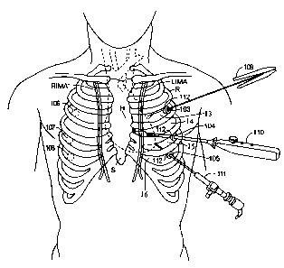
Fig. 5 shows the operative ports for performing the anastomosis of the
arterial
conduits onto the coronary arteries. A visualization port is placed in the
anterior wall of the
chest, typically through the fourth intercostal space, about 1-3 cm from the
sternum. The
precise placement of the visualization port is determined by the position of
the heart within
the patient's chest. A probe, such as a 22 gauge needle can be inserted
percutaneously through
the intercostal space while observing the anterior wall of the thoracic cavity
through the
thoracoscope. When the needle is observed entering the thoracic cavity above
the target
position, for instance above the LAD when the heart is in its native position,
the needle is
removed and a trocar is used to create an access port at that position. An
access cannula with
2o an internal diameter of 10-12 mm is placed in the access port and the
cardioscopic
microscope is inserted through the cannula. A cardioscopic microscope, adapted
especially
for this port-access CABG procedure is available from Karl Zeiss, Gmbh,
Germany. The
presently preferred configuration uses an OPMI~ microscope, model MDU or CS,
with an
NC31 microscope stand, an endoscopic adapter and a Port-Access StereoVision
Probe. Other
types of microscope-based and direct visualization systems which are
particularly well-suited
for use in the method of the present invention are disclosed in co-owned,
copending patent
applications Serial No. 08/135, 387, filed October 8, 1993, and Serial No.
08/227,366, filed
April 13, 1994, the complete disclosures of which are hereby incorporated
herein by
reference. With the microscope positioned in the visualization port, the left
anterior
3o descending coronary artery (LAD) should be within the field of view of the
microscope.
A number of instrument ports are placed about 3-S cm from the visualization
port to allow proper angulation of the instruments into the field of view of
the microscope.
Typically, two ports are placed near the stone in the third and fourth
intercostal spaces and
13
CA 02354677 2001-08-03
two more ports are placed to the left of the visualization port in the third
and sixth intercostal
spaces. An access cannula with an internal diameter of 5 mm is placed in each
of the
instrument ports.
Next the graft vessels, whether arterial or venous conduits, must be prepared
for anastomosis. Preferably, the distal ends of the graft vessels are prepared
outside of the
body by passing the distal end of the graft out through one of the access
ports. This simplifies
the procedure because the end of the graft can be prepared under direct
visualization with
magnifying surgical loupes and because standard surgical instruments can be
used for
preparing the graft rather than thoracoscopic instruments. The LIMA or RIMA
can be passed
out through one of the thoracic access ports before rerouting or tunneling the
vessel. The
RGEA can be passed out through one of the abdominal access ports before
tunneling the
RGEA through the diaphragm. If the graft vessel is too short to reach the
exterior of the body
through one of the access ports, the following graft vessel preparation
procedure can also be
carried out within the thoracic cavity using thoracoscopic instruments and
techniques. Prior to
15 preparing the graft vessel, the blood flow into the vessel must be stopped
by placing an
atraumatic clamp on the upstream end of the vessel. An atraumatic
thoracoscopic bulldog
clamp especially suited for this step of the procedure is described in co-
owned, copending
patent application serial number 08/265,477.
The graft vessel should be prepared by first detenmining the appropriate
length
2o of the conduit in order to reach the desired anastomosis site. The distal
end of the graft vessel
should then be skeletonized by stripping the pedicle away from the artery for
5-10 mm. The
distal end of the artery is transected to remove the ligating clip that was
previously applied. If
desired, Papavarin may be injected into the lumen of the artery to dilate it
and reverse any
arterial spasm. Depending on the technique preferred by the surgeon, the
distal end of the
25 graft vessel can be slit longitudinally to create a cobra head for the
anastomosis. Once
prepared, the graft vessel is reinserted into the thoracic cavity through the
access port.
When performing multiple anastomoses, it is preferable to do the most
difficult or most difficult to reach anastomosis first. For example, any
anastomosis to the
RCA or the PDA should be performed first since the most retraction of the
heart is necessary.
3o Following that, any anastornosis to the Cx or the OM branches should be
performed. Finally,
any anastomosis to the LAD can be performed last. The RIMA, RGEA or a vein
graft may be
used for anastomosis to the RCA or the PDA which are on the posterior aspect
of the heart.
Typically, the LIMA, RIMA or a vein graft is used when a graft is needed for
the Cx or the
14
CA 02354677 2001-08-03
OM branches because of their location on the left aspect of the heart. The
LIMA, or the
RIMA if the LIMA has already been used for the Cx, may be used for anastomosis
to the
LAD which is on the anterior aspect of the heart. Because the manifestations
of coronary
artery disease are highly variable, the extent of the disease should be
assessed
fluoroscopically beforehand and the anastomosis sites and the best use of the
available
conduits strategized carefully. The procedures for anastomosing to each of the
major
anastomosis sites will now be described. These procedures can be performed in
combination
to achieve complete revascularization of the heart.
Fig. 6 shows a first position of the heart for performing an anastomosis to
the
right coronary artery (RCA) or the posterior descending (PDA) branch. The
heart is
manipulated from outside of the body using instruments inserted through the
instrument ports
or the takedown ports in the patient's chest. Using the heart retractor
devices described below
in connection with Figs. 26 and 27 or any suitable means for manipulating the
heart from
outside of the body, the heart is rotated approximately 180 degrees to the
left of the patient to
position the RCA and/or PDA under the microscope in the visualization port.
With the heart
stabilized in this position, the distal extremity of the conduit vessel is
approximated to the
chosen anastomosis site and an end-to-side anastomosis is performed. The
likely graft vessels
for the RCA and the PDA, which include the RIMA and the RGEA, are shown in
phantom
lines in Fig. 6. After completion of the anastomosis, the heart is rotated
back to its native
2o position.
Fig. 7 shows an alternate position of the heart for performing the anastomosis
to the RCA or the PDA. In this variation of the procedure, the heart is
rotated approximately
180 degrees about an axis which is at an approximately 45 degree angle to the
sagittal axis of
the body. Flipped upward this way, the RCA and the PDA are positioned under
the
microscope in the visualization port. With the heart stabilized in this
position, the distal
extremity of the conduit vessel is approximated to the chosen anastomosis site
and an end-to-
side anastomosis is performed. The likely graft vessels for the RCA and the
PDA, which
include the RIMA and the RGEA, are shown in phantom lines in Fig. 7. After
completion of
the anastomosis, the heart is rotated back to its native position.
3o Fig. 8 shows the position of the heart for performing an anastomosis to the
circumflex artery (Cx) or the obtuse marginal (OM) branches. In order to
access the Cx or the
OM branches which are on the left aspect of the heart or the left posterior
aspect of the heart,
the heart is rotated toward the right by 45 to 90 degrees using retraction
instruments inserted
CA 02354677 2001-08-03
through the access ports. In this position the Cx and/or the OM branches will
be positioned
under the microscope in the visualization port. With the heart stabilized in
this position, the
distal extremity of the conduit vessel is approximated to the chosen
anastomosis site and an
end-to-side anastomosis is performed. The likely graft vessels for the Cx and
the OM
branches, which include the LIMA and the RIMA, are shown in phantom lines in
Fig. 8.
After completion of the anastomosis, the heart is rotated back to its native
position.
With the more difficult to reach anastomoses completed and the heart back in
its native position, as shown in Fig. 9 the anastomosis to the LAD can now be
completed.
With the heart in its native position, the LAD will be positioned under the
microscope in the
visualization port. With the heart stabilized in this position, the distal
extremity of the conduit
vessel is approximated to the chosen anastomosis site and an end-to-side
anastomosis is
performed. The likely graft vessels for the LAD, which include the LIMA and
the RIMA, are
shown in phantom lines in Fig. 9.
Alternatively to manipulating the heart within the closed chest to expose the
15 different aspects, a second visualization port and instrument ports can be
opened on the right
side of the chest, as shown by phantom lines XX in Fig. l, to access the right
coronary artery
RCA directly. In another alternative approach, right side access ports may be
used alone if
only the right coronary artery RCA and/or the obtuse marginal OM branches are
to be
revascularized or if the patient's anatomy favors a right side approach for
multivessel
20 revascularization.
Figs. 10-IS show the step-by-step sequence of creating an end-to-side
anastomosis. Referring now to Fig. 10, an incision 95 is made in the wall of
the coronary
artery CA, where the incision has dimensions selected to match those of the
distal end of the
25 internal mammary artery graft IMA. The incision 95 is made by first
piercing the arterial wall
using the tip of a scalpel (not illustrated). Scissors 96 are then introduced
through the
penetration and used to axially extend the penetration, as illustrated at 97
in Fig. 11.
The internal mammary artery IMA can be joined to the extended incision 97 in
the coronary artery CA by a variety of techniques, including suturing, laser
welding,
30 microstapling, and the like. In a currently preferred embodiment of the
method of the present
invention, it is preferred to use a continuous suturing technique as
illustrated in Figs. 10-15. A
length of suture 98 has needles 100 at either end, which are manipulated using
forceps 102 to
join the distal end 101 of the internal mammary artery IMA graft to the
opening created by the
16
CA 02354677 2001-08-03
incision 97 in the coronary artery CA, as shown in Figs. 11-15. The instrument
designs
presently preferred for performing the coronary anastomosis are described in
copending
application Serial No. 08/194,946, filed February 11, 1994, the entire
disclosure of which is
hereby incorporated herein by reference. Alternatively, an interrupted suture
technique for the
anastomosis can be used, as described in Rob and Smith's Operative Surgery>
Cardiac
Surgery for open-chest CABG surgery.
The presently preferred suture for port-access CABG surgery is a double-
armed suture of 8-10 cm length which was specially developed for this
procedure. The suture
has a first needle on one end and a second needle on the other end.
Preferably, the needles are
to 3/8 circle curved hardened stainless steel needles with tapered points. The
needles are
preferably attached to the suture by crimping. Alternatively, the needles may
be adhesively
bonded to be suture. The preferred suture material is a multifilament,
expanded PTFE suture
material with a size between 8-0 and 6-0 USP, preferably 7-0 USP. Suitable
suture material of
this type is available from W. L. Gore, Corporation under the tradename
Goretex~. A
15 contrasting color which is highly visible within the thoracic cavity, such
as black; blue or
white, is preferred for the suture material.
The configuration of this suture is especially advantageous for use in the
port-
access surgical CABG procedure. The suture can be inserted into the thoracic
cavity through
an access port and manipulated using thoracoscopic needle drivers to sew the
anastomosis
2o and to tie the suture within the thoracic cavity. Standard sutures, which
are normally much
longer, are very difficult to manipulate within the closed chest, especially
when tying the
suture using thoracoscopic instruments. The short length of the suture allows
the knots in the
suture to be pulled tight within the confines of the thoracic cavity while
grasping the needles
with the needle drivers. The multifilament, expanded PTFE suture material is
much easier to
25 handle and tie within the confines of the thoracic cavity than monofilament
suture material
which is generally stiffer and harder to handle. Additionally, the
multifilament, expanded
PTFE suture material has more resistance to damage than monofilament when it
is grasped
directly by the needle drivers.
Fig. 16 shows the heart of a patient after completion of a total
3o revascularization for multivessel coronary artery disease using port-access
techniques. Three
bypass grafts have been made, using the LIMA as a bypass to one of the OM
branches of the
Cx, the RIMA as a bypass to the LAD, tunneled via the transverse sinus, and
the RGEA as a
bypass to the PDA, tunneled through the diaphragm.
17
CA 02354677 2001-08-03
A sequential grafting technique or "skip grafting" is useful for achieving
total
revascularization when the number of significant coronary artery stenoses
exceeds the number
of available graft conduits. Sequential grafts are created by making a side-to-
side anastomosis
with a first coronary artery at an intermediate point on the graft vessel,
then an end-to-side
anastomosis between the distal end of the graft vessel and a second coronary
artery. Figs. 17-
18 show the step-by-step sequence of creating a side-to-side anastomosis. The
side-to-side
anastomosis is fashioned in a diamond-shaped manner, placing the graft vessel
arteriotomy at
right angles to the coronary arteriotomy. Small arteriotomies, 3-4 mm in
length, are used and
six to eight continuous stitches are placed through the coronary artery and
the graft vessel. An
to interrupted suture technique can also be used. Fig. 19 shows the heart of a
patient with a
completed sequential graft. The LIMA has been first grafted to the diagonal
branch of the left
coronary artery using a side-to-side anastomosis, then grafted to the LAD with
an end-to-side
anastomosis.
Free grafts using either arterial conduits or venous conduits can be used to
augment the in situ arterial grafts. Generally, the proximal end of a free
grafts is anastomosed
to the ascending aorta to provide an arterial blood source and the distal end
of the graft is
anastomosed to one of the coronary arteries. A common source of free grafts Is
the greater
saphenous vein. Other conduits used as free grafts include the lesser
saphenous vein, the
LIMA, the RIMA, the inferior epigastric artery, the splenic artery, the
subclavian artery, and
others. Fig. 20 shows the heart of a patient with a saphenous vein bypass
graft. The proximal
anastomosis can be created using suture techniques similar to those described
in connection
with Figs. 10-15 above with the exception that a thoracoscopic tissue punch
would be used to
create an aortotomy after the initial incision with a scalpel. Alternatively,
the proximal
anastomosis can be created using an anastomosis staple device, such as those
described in co-
owned, copending patent application serial number 08/394,333, the entire
disclosure of which
is hereby incorporated by reference.
Free grafts can be combined with in situ grafts or other free grafts to create
composite bypass grafts to help achieve total revascularization for
multivessel disease. For
example, a free graft can be anastomosed to the distal end of an in situ graft
like the LIMA or
3o RIMA when there is insufficient length of the graft after takedown.
Alternatively, a Y-graft
can be created as an alternative to the sequential grafts described above.
FIG. 21 shows the
heart of a patient with a Y-graft. The Y-graft was created by joining the
proximal end of a
RIMA free graft to an intermediate point on a LIMA in situ graft with an end-
to-side
18
CA 02354677 2001-08-03
anastomosis, then grafting the distal end of the RIMA to the Cx with an end-to-
side
anastomosis and grafting the distal and of the LIMA to the LAD. Other conduits
including
arterial and venous grafts can be combined in various combinations to create
composite
grafts.
Instrument Descriptions
Figs. 22-47 show an armamentarium of instruments for facilitating the port-
access multivessel CABG procedure. Fig. 22 shows a first embodiment of a
tunneler for
retracting the pulmonary artery away from the ascending aorta to facilitate
tunneling the
RIMA through the transverse sinus. The tunneler has an elongated shaft of
sufficient length to
to reach the great vessels of the heart from the takedown ports in the left
lateral side of the chest,
typically 1 S-30 cm in overall length. There is a handle on the proximal end
of the shaft. The
distal portion of the shaft is curved to facilitate passing the tunneler
through the transverse
sinus from the left side of the heart. The distal tip of the shaft is rounded
to make it
atraumatic. There is a hole through the shaft near the distal tip of the
tunneler. In use, a
t5 silastic tape or elastomeric tube is threaded through the hole and the
distal end of the tunneler
is inserted through one of the takedown ports. Under thoracoscope observation,
the curved
distal portion is inserted behind the pulmonary artery and the ascending aorta
and passed
through the transverse sinus to the right side of the heart, as shown in Fig.
23. When the distal
tip of the tunneler emerges on the right side of the heart, a grasper is
inserted through one of
2o the access ports, typically one of the takedown ports on the left lateral
side of the chest, to
grasp one side of the tape. The retractor is withdrawn and the ends of the
tape are passed out
through the access ports, preferably one of the takedown ports located at the
third or fourth
intercostal space, and tension is placed on the tape to retract the trunk,
thereby widening the
transverse sinus. With the pulmonary trunk retracted, a grasping instrument,
such as the
25 articulated tunneling grasper of Fig. 26, can more easily be reached
through the transverse
sinus.
A basic embodiment of the articulated tunneling grasper is shown in Fig. 24.
The articulated tunneling grasper has an elongated tubular shaft with a handle
on the proximal
end. A multilink articulator is attached to the distal end of the shaft. The
multilink articulator
3o is shown indetail in Fig. 25. The multilink articulator has a head which
attaches to the distal
end of the shaft. Two links are pivotally attached to the head. The first link
is a straight link.
The proximal end of the first link is pivotally attached to the head. The
second link is an L-
shaped link with a long leg that is approximately the same length as the first
link, and a short
19
CA 02354677 2001-08-03
leg extending perpendicular from the proximal end of the long leg. The second
link is
pivotally attached to the head at the proximal end of the long leg. An
actuator rod that passes
through the tubular shaft connects the end of the short leg with a sliding
actuator button on
the handle. The first link and the second link cross one another and their
distal ends are
pivotally attached to a third link. The third link is an L-shaped link with a
long leg extending
distally, and a short leg extending perpendicular from the proximal end of the
long leg. When
the actuator rod is in its neutral position the multilink articulator is in a
relatively straight
position, as shown in Fig. 24 by solid lines XX. When the actuator rod is
moved distally with
respect to the head, it pivots the second link counterclockwise, as shown in
Fig. 24 by
phantom lines XX'. The relative motion of the first and second links, in turn,
pivots the third
link counterclockwise, as shown. When the actuator rod is moved proximally
with respect to
the head, it pivots the second link clockwise, as shown in Fig. 24 by phantom
lines XX". The
relative motion of the first and second links, in turn, pivots the third link
clockwise. The distal
end of the multilink articulator can thus pivot approximately 90 degrees in
either direction.
Various end effectors can be attached to the distal end of the multilink
articulator for performing different tasks. The possible end effectors include
a simple hole, as
shown in Fig. 24, for placing a tape through the transverse sinus for
retracting the pulmonary
trunk, or a heart retraction device, such as a suction retractor or finger
retractor, as discussed
in more detail below, or a grasping mechanism, such as a cable-actuated
grasper.
2o In one particularly preferred embodiment, shown in Fig. 26, a cable-
actuated
grasper is mounted on the distal end of the multilink articulator shown in
Fig. 24. The grasper
has a first and second jaw with grasping surfaces on the facing surfaces of
the jaws. At least
one of the jaws, and preferably both jaws, are pivotally attached to the
distal end of the third
link. An actuator cable extends from a control button on the handle, through
the tubular shaft,
and to a linkage connected to the grasper jaws. The jaws of the grasper can be
actuated to
open and close using the control button.
In use, the articulated tunneling grasper is inserted through one of the
takedown ports in a straight position. The distal end of the grasper is
inserted behind the
pulmonary artery and the ascending aorta, and through the transverse sinus, as
shown in Fig.
27. The multilink articulator is actuated to assume an appropriate curve to
pass easily through
the transverse sinus. Once the distal end of the grasper emerges from the
transverse sinus on
the right side of the heart, as shown in Fig. 27, the multilink actuator can
be used to
manipulate the grasper closer to the RIMA. Another grasper may be inserted
through another
CA 02354677 2001-08-03
~ i
access toward to assist with handling the RIMA to the particular grasper. The
grasper is
opened, then closed to grasp the pedicle of the RIMA so as not to damage the
vessel. The
tunneling grasper, with the RIMA in its grasp, is withdrawn through the
transverse sinus to
the left side of the heart. The RIMA has thus been tunneled through the
transverse sinus from
the right side of the heart to the left side, as discussed above in relation
to Fig. 2.
Tunneling the RIMA through the transverse sinus from the right side of the
heart to the left side is the currently preferred path for rerouting the RIMA
for attachment to
the Cx or the OM branches. Alternatively, the RIMA can be routed across the
anterior side of
the heart using the articulated tunneler or another thoracoscopic grasping
device. When
rerouting a graft vessel, particularly when tunneling through a space such as
the transverse
sinus, it is important to avoid twisting or kinking the graft vessel. One way
to avoid twisting
the vessel is to mark a line along the vessel which can serve as an indicator
of whether the
vessel is straight. For instance, the vessel can be marked by drawing a line
along the vessel or
on the pedicle with a surgical marker containing a nontoxic ink, such as
methylene blue. The
t5 vessel is preferably marked before takedown to assure that the vessel is in
a straight condition
when it is marked. Alternatively, the clips or sutures that are used to ligate
side branches of
the vessel during takedown can be used as markers to determine if the graft
vessel is straight
when it is rerouted.
Fig. 28 shows a first embodiment of a heart retractor with a finger-like
2o manipulator on the distal end for rotating the heart within the closed
chest of the patient to
expose each of the coronary arteries to be anastomosed. The retractor has an
elongated shaft
of approximately 15-30 cm with a handle on the proximal end of the shaft. The
distal end of
the retractor shaft is curved to create a finger-like manipulator. The curved
manipulator has a
radius of curvature in one preferred embodiment of approximately 4.5 cm. The
radius of
25 curvature in other embodiment can range from 3.5-6 cm. The curvature of the
finger-like
manipulator subtends an arc of approximately 90 to 180 degrees. The finger-
like manipulator
has an outer diameter of approximately 5-10 mm. The finger-like manipulator is
preferably
molded of a rigid plastic, such as ABS or nylon. Alternatively, the finger-
like manipulator can
be made of metal, such as stainless steel. In one particular alternative
embodiment, the finger-
30 like manipulator is made of annealed 316 stainless steel which is malleable
so that it can be
manually bent to the desired curvature. The exterior of the finger-like
manipulator is covered
with an absorbent and/or high friction material to assist in grasping and
manipulating the
heart. The covering of the finger-like manipulator extends to the very distal
end of the
21
CA 02354677 2001-08-03
manipulator and covers the rounded distal tip. The preferred material for
covering the finger-
like manipulator is a nonwoven polyester fabric, embossed with an open mesh
pattern. The
nonwoven polyester gives the covering absorbency, while the open mesh pattern
improves the
friction of the surface. A fabric with a self-sticking adhesive surface is
preferred for
convenience in assembling the retractor. The currently preferred material for
the covering of
the finger-like manipulator is a 2.4 oz. nonwoven, embossed polyester medical
tape with
WetstickTM adhesive available from Avery Dennison, Specialty Tape Division,
Painesville,
OH.
Alternate materials for the covering of the finger-like manipulator include
1o nonembossed, nonwoven fabrics, such as polyester surgical felt. While the
absorbency of
these materials is quite acceptable, the friction of the smooth, nonembossed
fabric is less than
for embossed materials. Examples of acceptable materials in this category
include Fastsorb
820 and Exsorbx 400 available from Berkshire Corp, Great Barrington, MA or
Surgical Felt
6077 or 6079 available from BARD, Vascular Surgery Division, Haverhill, MA.
Other
~5 materials suitable for covering the finger-like manipulator include woven
materials and knit
materials made of polyester, cotton or other fibers. These materials also tend
to have a lower
coefficient of friction for gripping tissue. Another alternate material for
the covering of the
finger-like manipulator is a composite material, including a first layer of a
highly absorbent
material, like surgical felt, and a second layer of mesh-like material to
increasing the
2o coefficient of friction for gripping the surface of the heart.
The covering material is preferably die cut in a pattern that easily conforms
to
the shape of the finger-like manipulator. Fig. 30 shows a die-cutting pattern
for the covering
material to cover a finger-like manipulator having a radius of curvature of
4.5 cm which
subtends 180 degrees of arc, and an outer diameter of 8 mm, such as the one
shown in Fig.
25 28. Fig. 30B shows an enlarged detail drawing of the die-cutting pattern of
Fig. 30A. The
self-adhesive covering material is cut to this pattern and adhesively bonded
to the exterior of
the finger-like manipulator.
The absorbency, combined with the texture of the covering, gives the retractor
a good frictional grip on the surface of the heart. Keeping the interface
between the retractor
3o surface and the surface of the heart dry is important for maintaining a
good frictional grip.
Another preferred embodiment of the retractor, shown in Fig. 29, combines
suction irrigation
with the retractor to augment the absorbency of the covering material. In this
embodiment, a
suction lumen extends through the shaft of the retractor and through the
finger-like
22
CA 02354677 2001-08-03
manipulator. A series of suction holes connect the suction lumen with the
surface of the
finger-like manipulator on the inner curve of the distal end. A constant or
intermittent suction
through the holes will keep the covering material dry to improve the
frictional grip on the
surface of the heart.
In use, the retractor is typically inserted into the thoracic cavity through
one of
the takedown ports on the left lateral side of the chest. The curved finger-
like manipulator of
the retractor is hooked around the apex of the heart, as shown in Fig. 31. The
retractor can be
used to rotate or translate the position of the heart within the closed chest.
For example, the
retractor can be used to roll the heart toward the right side of the patient
to expose the Cx or
to the OM branches on the left aspect of the heart to the microscope in the
visualization port.
This position of the heart is shown in Fig. 7. The retractor can also be used
to lift the apex of
the heart and flip the heart 180 degrees to expose the RCA or PDA on the
posterior aspect of
the heart to view. This position of the heart is shown in Fig. 9.
The retractor can be fixed to the operating table to stabilize the heart in
the
15 desired position; as shown in Fig. 32. A positioning device, such as the
Omnitract model
XXX or the Mediflex model XXX, is attached to the operating table and bent to
the correct
position and locked in place. A clamp on the distal end of the positioning
device is attached to
the proximal end of the retractor to hold it in place and maintain the
position of the heart
during the course of the grafting step.
2o Fig. 33A shows a side view of an embodiment of a suction heart retractor
for
manipulating the heart within the closed chest of the patient. The retractor
has an elongated
tubular shaft having a suction cup-shaped manipulator on the distal end. The
suction cup-
shaped manipulator may be mounted straight on the shaft or it may be mounted
at an angle to
the shaft. In one particularly preferred embodiment, there is a 45 degree bend
near the distal
25 end of the shaft so that the suction cup-shaped manipulator is mounted at a
45 degree angle to
the proximal shaft. In either embodiment, the suction cup-shaped manipulator
is preferably
flexibly mounted to the distal end of the shaft. A vacuum lumen extends
through the tubular
shaft from the proximal end to the distal end. The distal end of the vacuum
lumen is in fluid
communication with the interior of the suction cup-shaped manipulator. The
proximal end of
30 the vacuum lumen is adapted for attachment to a vacuum source. A fitting
for connecting to
the vacuum source, such as a barb fitting or luer fitting, may be attached to
the proximal end
of the tubular shaft, or a flexible extension tube may be attached to the
proximal end of the
shaft with a fitting at the far end of the extension tube.
23
CA 02354677 2001-08-03
The shaft of the retractor is preferably made of a rigid material that will
support the forces required for manipulating the heart without significant
deformation.
Acceptable materials for the retractor shaft include stainless steel and
liquid crystal polymer.
To facilitate forming an angled or curved shaft, a mineral filled liquid
crystal polymer (e.g.
calcium carbonate) is preferred. This material can be heat formed at 350 to
400 degrees F.
Fig. 33B shows a longitudinal cross section of the distal end of the heart
retractor of Fig. 33A, and Fig. 33C shows a distal end view of the heart
retractor of Fig. 33A.
The suction cup-shaped manipulator has an external diameter of approximately
12 to 50 mm
for a surface area of approximately 110 to 1960 mm2. The surface area of the
suction cup-
to shaped manipulator allows a firm grip on the surface of the heart when a
vacuum is applied to
the interior of the suction cup, without causing vacuum damage to the tissue.
A valve on the
shaft of the retractor allows the surgeon to coptrol the vacuum to turn it on
and off.
Preferably, the vacuum should be limited to a maximum of 150 mmHg to avoid
tissue
damage. The suction cup-shaped manipulator is made of a soft, flexible
elastomeric material,
t5 such as silicone rubber with a hardness of approximately 40 to 80 Shore A
durometer. The
soft, flexible suction cup-shaped manipulator is designed so that when a
vacuum is applied
within the suction cup, the suction cup conforms to the surface of the heart
and does not cause
deformation of the heart tissue.
The distal surface of the suction cup-shaped manipulator is textured to create
a
2o high friction surface. In one particularly preferred embodiment, the
suction cup-shaped
manipulator has a pattern of bumps on the distal surface and a circular ridge
around the
periphery of the suction cup. The bumps in one preferred embodiment have a
height of
approximately 1 mm with a 120 degree conical end and straight sides. Other
geometries for
the friction-increasing bumps include conical, cylindrical or hemispherical,
as well as other
25 possible geometries. The circular ridge around the periphery has a height
of approximately 1-
2 mm. The geometry and the pattern of the bumps create a reliable friction
grip on the surface
of the heart under vacuum without causing any damage to the heart tissue. An
alternative
embodiment of the retractor has an absorbent high friction material adhesively
attached to or
cast into the distal surface of the suction cup-shaped manipulator in place of
the pattern of
3o bumps. A suitable absorbent high friction material for this application is
a nonwoven
polyester fabric embossed with an open mesh pattern.
In use, the distal end of the retractor is inserted through one of the access
ports,
typically one of the takedown ports in the left lateral side of the patient's
chest. The soft,
24
CA 02354677 2001-08-03
flexible nature of the suction cup-shaped manipulator allows it to be folded
or collapsed as it
is pushed through the access port. The retractor can be inserted through an
access cannula or
the cannula can be removed from the access port to facilitate insertion of the
suction cup-
shaped manipulator directly through the access port. In one preferred
embodiment of the
method, suction cup-shaped manipulator is placed on the anterior surface of
the heart near the
apex, as shown in Fig. 34, and a vacuum is applied to grip the surface of the
heart. From this
position, the retractor can be used to rotate the heart in either direction.
In Fig. 35, the
retractor has been used to rotate the heart approximately 90 degrees to the
right to expose the
Cx and the OM branches on the left aspect of the heart to view. The retractor
can also be used
1o to rotate the heart 180 degrees to the left to expose the RCA and PDA on
the posterior aspect
of the heart, as in Fig. 8. In an alternative embodiment of the method, the
suction cup-shaped
manipulator is placed on the posterior side of the heart near the apex and a
vacuum is applied
to grip the surface of the heart. Then, the retractor is used to lift and
rotate the heart to flip it
180 degrees to expose the RCA and PDA on the posterior aspect of the heart, as
in Fig. 7.
15 This retractor can also be fixed to the operating table to stabilize the
heart in the desired
position similarly to the embodiment of Fig. 32.
Fig. 36 shows a third retraction device for manipulating the heart within a
patient's closed chest. The retraction device has an elongated tubular shaft.
The tubular shaft
has a right angle bend at the distal end. A first end of a flexible snare is
attached to the shaft
2o at the distal end. The second end of the flexible snare extends through a
lumen within the
tubular shaft and attaches to a sliding handle at the proximal end. The snare
is made of a
flexible wire or band. Preferably, the flexible wire or band is covered with a
soft, flexible
friction material to increase the surface area and to improve the frictional
grip on the heart.
Suitable materials for the covering of the snare include soft, flexible
polymers or elastomers
25 or absorbent, high-friction fabrics. The flexible wire or band of the snare
is preferably made
of a highly resilient material such as a superelastic nickel/titanium alloy or
a spring temper
stainless steel or titanium alloy.
Fig. 37 shows the heart retractor of Fig. 36 in a predeployed position for
insertion through an access cannula. When the sliding handle is in a proximal
position, the
3o snare forms a small loop, as shown in Fig. 37, which easily deforms to fit
through a 10 mm
access cannula. When the sliding handle is in a distal position, the snare
forms a large loop, as
shown in Fig. 36, which is large enough to encircle the heart. The wire is
preferably
preshaped so that the snare opens up in a loop perpendicular to the axis of
the distal segment
CA 02354677 2001-08-03
of the shaft. Fig. 38 shows a cross section of a patient showing the
retraction device inserted
into the thoracic cavity through one of the access ports with the snare
encircling the heart.
From this position, the retractor can be used to manipulate the heart to a
desired position. For
example, the retractor can be used to lift and rotate the heart to flip it 180
degrees to expose
the RCA and PDA on the posterior aspect of the heart, as in Fig. 7.
Fig. 49 shows a fourth retractor device for manipulating the heart within the
close chest of a patient in a predeployed position for insertion through an
access cannula. The
retractor has an elongated tubular shaft with a handle on the proximal end. In
a preferred
embodiment, the distal end of the shaft has an angled portion at an
approximately 0 to 45
to degree angle to the proximal portion of the shaft. A flexible band extends
through a lumen
within the tubular shaft and extends beyond the distal end of the shaft. The
distal end of the
band is pivotally attached to a distal link. The distal link is, in turn,
pivotally attached to a
proximal link which, in turn, is pivotally attached to the distal end of the
tubular shaft. The
proximal end of the band is attached to a sliding actuator button on the
handle. When the
~5 activator button is in a proximal position, the distal portion of the
flexible band is positioned
parallel to and in close proximity to be proximal and distal links, as shown
in Fig. 39. When
the activator button is in a distal position, the distal portion of the
flexible band extends from
the instant end of the tubular shaft to form a loop together with the proximal
and distal links,
as shown in Fig. 40. In the illustrative embodiment of Figs. 39 and 40, the
handle has a
2o semicircular cassette for storage of the band when the band is in the
proximal position. Other
embodiment of the retractor could have a circular storage cassette or a linear
configuration for
storing the retracted band. Preferably, the flexible band is made of a
resilient material such as
a spring tempered stainless steel or titanium alloy. The proximal and distal
links are also
preferably made of a stainless steel or titanium alloy. The surfaces of the
flexible band and/or
25 the proximal and distal links facing the inside of the loop are preferably
covered with a soft,
flexible friction material to improve the frictional grip a the retractor on
the heart. Suitable
materials for the covering of the snare include soft, flexible polymers or
elastomers or
absorbent, high-friction fabrics.
In use, the distal end of the retractor is inserted into the thoracic cavity
to one
3o of the access ports, typically one of the takedown ports on the left
lateral side of the chest.
The actuator button is advanced distally to open the loop large enough to
encircle the heart.
The loop is passed around the heart from the apex end and tightened gently
around the heart,
as shown in Fig. 41. A force limiter can be incorporated into the actuating
mechanism of the
26
CA 02354677 2001-08-03
retractor to prevent excessive force on the heart. From this position, the
retractor can be used
to manipulate the heart to a desired position. For example, the retractor can
be used to lift and
rotate the heart to flip it 180 degrees to expose the RCA and PDA on the
posterior aspect of
the heart, as in Fig. 7.
Figs. 42-45 show a topical hypothermia device which can be used to improve
myocardial protection during the port-access multivessel CABG procedure. The
topical
hypothermia device has a flexible heat exchanger which has at least one fluid
passage
therethrough to circulate a cooling fluid. The flexible heat exchanger is
collapsible to a
predeployed position which can easily fit through an access port into the
chest of the patient.
1o The flexible heat exchanger is attached to the distal end of an elongated
tubular shaft. The
tubular shaft is preferably made of a rigid material such as stainless steel
or a rigid plastic. An
inflow lumen extends through the tubular shaft and is fluidly connected to the
flexible heat
exchanger. A return lumen extends through the tubular shaft parallel to the
inflow lumen. The
inflow lumen and the return lumen may be formed of extruded plastic tubes
which are
15 inserted through the tubular shaft. Alternatively, the lumens may be formed
integrally with
the tubular shaft by extrusion. The proximal ends of the inflow lumen and the
return lumen
are adapted for attachment to a circulating pump and a reservoir of cooling
fluid, which is
preferably a saline solution.
In the illustrative embodiment of Fig. 42, the flexible heat exchanger is made
2o from two sheets of flexible plastic which are heat sealed or RF sealed
together to form a
serpentine cooling path through the heat exchanger. Preferred materials for
manufacturing the
flexible heat exchanger include polyurethane, vinyl, polypropylene, nylon,
etc. The flexible
heat exchanger, in one preferred embodiment, has a length of 12-18 cm and a
width of 7-10
cm. Optionally, the flexible heat exchanger may have a flexible backbone which
extends from
25 the distal end of the tubular shaft to the distal edge of the heat
exchanger. The flexible
backbone may be made from a flexible polymer, elastomer, or a resilient metal
wire, such as
spring temper stainless steel or a superelastic nickel/titanium alloy, or a
composite of metal
and plastic. The flexible heat exchanger is rolled, folded or twisted and
placed in an
introduces sheath in the predeployed position as shown in Fig. 43. Preferably,
the introduces
3o sheath is sized to fit through an access cannula with a 10-12 mm internal
diameter.
In use, the topical hypothermia device is prepared in the predeployed position
by first priming the flexible heat exchanger by filling it with cooling fluid
and connecting the
proximal end of the inflow lumen and the return lumen to the circulating pump
and the
27
CA 02354677 2001-08-03
reservoir of cooling fluid, respectively. The flexible heat exchanger is
rolled and covered with
the introducer sheath. The topical hypothermia device is inserted through one
of the access
ports in this predeployed position. The distal end of the introducer sheath is
placed under the
heart and then withdrawn proximally with respect to the flexible heat
exchanger, thereby
placing the heat exchanger underneath the heart. Alternatively, the sheath can
be withdrawn
after the topical hypothermia device is introduced through the access port and
the flexible
heat exchanger placed under the heart with the help of the flexible backbone.
The circulating
pump is turned on to force cooling fluid into the flexible heat exchanger and
through the
cooling passage. The flexible heat exchanger inflates with cooling fluid and
spreads out under
the heart to make good thermal contact with the myocardium, as shown in Fig.
45. Preferably,
the flexible heat exchanger is constructed so that it curves to conform to the
exterior of the
heart when inflated to the deployed position, as shown in Fig. 44, to create a
better thermal
contact with the myocardium. Typically, a cooling fluid at 0-4 degrees Celcius
is circulated
through the heat exchanger with a flow rate of greater than 350 ml/min to
rapidly cool the
~5 heart.
In an alternate embodiment of the topical cooling device, the flexible heat
exchanger may also be covered with a thermal insulating material, such as
surgical felt, to
prevent thermal shock to the myocardial tissue. Another way to avoid thermal
shock to the
myocardial tissue is to use a more moderate temperature for the cooling fluid,
with better
2o thermal contact and a higher flow rate to rapidly cool the myocardium
without the risk of
thermal shock.
Fig. 46 shows an alternate embodiment of the topical cooling device, which is
similar to the embodiment of Fig. 42 except for the construction of the
flexible heat
exchanger. In this embodiment; the flexible heat exchanger is in the form of a
ring made by
25 heat sealing two sheets of plastic together. The cooling fluid enters one
side of the ring-
shaped heat exchanger and follows a serpentine cooling path through the heat
exchanger
around to the other side of the ring. A preformed, resilient wire loop is
attached around the
outside of the ring-shaped heat exchanger to initialize the shape of the heat
exchanger during
deployment, as shown in Fig. 47.
30 The topical cooling device can be used alone to induce hypothermia cardiac
arrest in the patient's heart or the topical cooling device can be used in
conjunction with
cardioplegic arrest to improve the myocardial protection during the surgical
procedure. In
addition, the topical cooling device can be used to rewarm the heart after the
completion of
28
CA 02354677 2001-08-03
the surgical procedure by circulating warm fluid through the flexible heat
exchanger. In
addition to the multivessel CABG procedure of the present invention, the
topical cooling
device will find utility for improving myocardial protection in any open-chest
or closed-chest
cardiac surgery.
Another closely related surgical approach for performing closed-chest
multivessel CABG surgery is through an anterior mediastinotomy, that is,
through an incision
into the mediastinum, the mass of tissues and organs between the lungs that
includes the
heart. Another term for this surgical approach is a rib-sparing, anterior mini-
thoracotomy.
There are two ways to perform the anterior mediastinotomy for this approach.
The first way is
1o through an intercostal incision 25-50 mm long in the fourth or fifth
intercostal space to the
left of the sternum, as shown in Fig. 48. The second way is to create a larger
access port by
removing either the third, fourth or fifth costal cartilage, preferably on the
left side of the
sternum. V~hen one of the costal cartilages is removed, it creates an access
port approximately
50-60 mm square, as shown in Fig. 49. The access port can be held open using a
tissue
15 spreader for an access cannula which is oval or square in shape. Actual
cutting or removal of
ribs is not necessary. The best position for the port may be decided by
viewing through the
lateral IMA takedown ports in the third or fourth intercostal space and
probing with a needle
to find the best position and line of sight for the particular anastomosis
site. It should be noted
that, because the anterior mediastinotomy may cut across the path of the
internal mammary
2o artery, it is preferable to make the access port after completion of the
IMA takedown.
A tissue spreader or oval cannula for retraction would be useful to maintain
the access channel. Retraction of the ribs should be kept to a minimum in
order to reduce the
trauma to the patient. For introduction without retraction of the ribs, the
oval cannula should
have interior dimensions of approximately 12 mm width and 25-50 mm length, and
a thin
25 wall of approximately 1 mm thick. For varying degrees of retraction, the
width of the oval
cannula can be increased anywhere from 12 mm to 25 mm, which should be
sufficient for
adequate visualization and instrument access. Visualization and instrument
insertion can thus
be accomplished through a single elongated access port, rather than using
separate
visualization and instrument ports as in the port-access approach described
above.
3o Visualization can be accomplished using a surgical microscope, as described
above, or by
direct visualization through the access port, with or without magnifying
loupes. The cannula
should be configured to facilitate retraction of the pedicle through the lumen
of the cannula
without harm so that the distal end of the graft vessel can be prepared for
anastomosis outside
29
CA 02354677 2001-08-03
of the body under direct visualization. Therefore, the cannula should have no
sharp edges that
could harm the graft vessel or pedicle. The insertion length of the cannula
should be about 25-
50 mm.
Preferably, illumination means are incorporated into the oval cannula or into
the tissue spreader used to maintain the access channel. A light conduction
path is
incorporated into the wall of the oval cannula or into the blades of the
tissue spreader to direct
a beam of light distally onto the surgical site. A light source is connected
to the light
conduction path. The light source can be integrated into the device or an
external light source
may be connected to the device by an optical cable.
1o An exemplary embodiment of an illuminated access device is shown in a top
view in Fig. 50 and a side view in Fig. S 1. This particular embodiment is an
illuminated oval
cannula, however the following inventive features can also be incorporated
into a blade
retractor, tissue spreader, or standard circular access cannula. Optical
fibers are embedded
into the wall of the oval cannula. The optical fibers terminate at the distal
end of the cannula
to direct a beam of light distally toward the surgical site. A narrow or
diffuse beam of light
can be created depending on the arrangement and the numerical aperture of the
optical fibers.
At the proximal end of the cannula, the optical fibers gather together into an
optical connector
for connection to an external light source. In one currently preferred
embodiment, a
multiplicity of small diameter optical fibers are distributed evenly about the
periphery of the
oval cannula. The wall of the oval cannula can be made of an opaque material
to avoid light
escaping from the optical fibers from interfering with visualization through
the lumen of the
cannula. Alternatively, the interior and/or exterior wall of the cannula can
be made
transparent or translucent to create a diffuse ambient light within or around
the cannula.
Anastomosis between the graft vessel and the coronary artery is performed
using instruments inserted through the access port. One advantage of this
approach is that the
access port is large enough so that the surgeon can insert a finger through
the access port or
oval cannula to directly palpate the heart, for instance to locate a stenosis
in the coronary
artery. It may be advantageous to elevate the heart within the thoracic cavity
to facilitate
palpate the heart and/or performing the anastomosis. A device similar to the
topical cooling
3o devices of Figs. 42-47 may be used to elevate the heart within the thoracic
cavity by insetting
it underneath the heart and inflating it, with or without circulating cooling
fluid. The
tunneling and retraction devices of Figs. 22-41 can be used through the access
port or through
the takedown ports to manipulate the heart to expose different aspects of the
heart for
CA 02354677 2001-08-03
visualization and anastomosis of multiple coronary arteries according to the
methods
described above. Alternatively, a second mediastinal access port can be opened
on the right
side of the chest to access the right coronary artery directly. In another
alternative approach, a
right side mediastinal access port may be used alone if only the right
coronary artery is to be
revascularized or if the patient's anatomy favors a right side approach for
multivessel
revascularization.
31