Language selection

Search

Patent 2354693 Summary

Third-party information liability

Some of the information on this Web page has been provided by external sources. The Government of Canada is not responsible for the accuracy, reliability or currency of the information supplied by external sources. Users wishing to rely upon this information should consult directly with the source of the information. Content provided by external sources is not subject to official languages, privacy and accessibility requirements.

Claims and Abstract availability

Any discrepancies in the text and image of the Claims and Abstract are due to differing posting times. Text of the Claims and Abstract are posted:

  • At the time the application is open to public inspection;
  • At the time of issue of the patent (grant).
(12) Patent: (11) CA 2354693
(54) English Title: CONVECTIVE AIR TEMPERATURE AND HUMIDITY SENSOR
(54) French Title: CAPTEUR CONVECTIF DE TEMPERATURE ET D'HUMIDITE DE L'AIR AMBIANT
Status: Expired and beyond the Period of Reversal
Bibliographic Data
(51) International Patent Classification (IPC):
  • G01W 1/17 (2006.01)
  • G01K 1/20 (2006.01)
  • G01N 25/56 (2006.01)
(72) Inventors :
  • WALKER, JEFFERY CHARLES (United Kingdom)
  • DEEDMAN, DAVID KENNETH (United Kingdom)
  • FLEMING, NIGEL PAUL (United Kingdom)
  • OUGHTON, BRIAN WILLIAM (United Kingdom)
  • SANDOE, IAIN DERECK (United Kingdom)
  • WILTON, PAUL MILES (United Kingdom)
(73) Owners :
  • SELEX ES LTD
(71) Applicants :
  • SELEX ES LTD (United Kingdom)
(74) Agent: SMART & BIGGAR LP
(74) Associate agent:
(45) Issued: 2005-08-02
(86) PCT Filing Date: 1999-12-08
(87) Open to Public Inspection: 2000-06-22
Examination requested: 2002-11-19
Availability of licence: N/A
Dedicated to the Public: N/A
(25) Language of filing: English

Patent Cooperation Treaty (PCT): Yes
(86) PCT Filing Number: PCT/GB1999/004138
(87) International Publication Number: WO 2000036439
(85) National Entry: 2001-06-08

(30) Application Priority Data:
Application No. Country/Territory Date
9827186.9 (United Kingdom) 1998-12-11

Abstracts

English Abstract


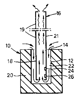
The sensor has an outer member (10) formed with an upwardly
directed hole (12) having an open upper end (14). An inner member
in the form of a tube (16) is provided having a lower portion (18)
positioned in the hole (12) and an upper portion (19) which projects
above the outer member (10). Solar radiation applied to the upper
portion (19) of the tube (16) creates a chimney effect which causes
air to flow upwardly inside the tube (16) and downwardly from the
open upper end (14) through a space (22) between the inner and outer
members (10, 16). Sensing devices (24, 26) for sensing temperature
and humidity are arranged within the outer member (10) and in the
air flow path.


French Abstract

L'invention porte sur un capteur possédant un élément (10) interne formé d'un trou (12) orienté vers le haut et pourvu d'une extrémité (14) supérieure ouverte. Un élément intérieur de la forme d'un tube (16) est constitué d'une partie (18) inférieure positionnée dans le trou (12), et d'une partie (19) supérieure qui fait saillie de l'élément (10) externe. Un rayon solaire appliqué sur la partie (19) supérieure du tube (16) crée un effet de cheminée qui fait monter l'air à l'intérieur du tube (16) et qui le fait descendre de l'extrémité (14) supérieure ouverte par un espace (22) se trouvant entre les éléments (10, 16) interne et externe. Les capteurs (24, 26) de température et d'humidité sont placés à l'intérieur de l'élément (10) externe et dans la voie d'écoulement d'air.

Claims

Note: Claims are shown in the official language in which they were submitted.

5
CLAIMS:
1. A sensor comprising; a tube having a first portion
and a second portion, a shielding member raving a cavity
therein, and at least one sensing device for sensing a
characteristic of ambient air, wherein the first portion of
the tube is positioned within the cavity of the shielding
member and the second portion of the tube is arranged to
protrude from the cavity, there being a clearance between
the outer surface of the first portion of the tube and the
surface of the shielding member surrounding the cavity such
that heat applied to the second portion of the tube causes
air to flow through. the tube in a direction from the first
portion towards the second portion thereby drawing fresh air
into the cavity through the clearance between the tube and
the shielding member and wherein the sensing device is
located within the cavity of the shielding member.
2. A sensor according to claim 1 in which the sensing
device is arranged on the first portion of the tube.
3. A sensor according to claim 1 in which the sensing
device is arranged on the inside of the first portion of the
tube.
4. A sensor according to any one of claim 1 to 3 in
which the cavity in the shielding member has a closed lower
end.
5. A sensor according to claim 4 in which the first
portion of the tube has a first end arranged adjacent the
closed end of the cavity.
6. A sensor according to any one of claims 1 to 5 in
which the shielding member is made from an insulative
material.

6
7. A sensor according to arty one of claims 1 to 6 in
which the tube is made from a conductive material.
8. A sensor according to claim 7 in which the tube is
made from a material which is at least partly metallic.
9. A sensor according to any one of claims 1 to 8
wherein the tube is fluted.
10. A sensor according to any one of claims 1 to 9
comprising a sensing device which senses temperature.
11. A sensor according to any one of claims 1 to 9
comprising a sensing device which senses humidity.
12. A sensor according to any one of claims 1 to 11 in
which the tube and the cavity are arranged to be
substantially coaxial.
13. A sensor according to any one of claims 1 to 12 in
which the cavity is hole of circular transverse cross
section.
14. A sensor according to any one of claims 1 to 13 in
which the tube is of circular transverse cross section,

Description

Note: Descriptions are shown in the official language in which they were submitted.


CA 02354693 2002-11-19
26158-132
1
CONVECTIVE AIR TEMPERATURE AND HUMIDITY SENSOR
The invention relates to a sensor and is primarily concerned with a sensor for
sensing
temperature andlor humidity of ambient air
One of the problems with sensors used to sense temperature and/or humidity is
that of
maintaining accuracy in the presence of strong sunlight.. It is known to
install sensing
devices in ventilated housings such as a Stevenson Screen which are coloured
white to
minimise the effect of sunlight. However, white makes the sensor highly
visible which is not
always desirable.
When measuring temperature and/or humidity, a 'flow of air over the sensing
device should
ideally be provided. In the Stevenson Screen, air flows through the ventilated
housing but
relies on a slight wind to achieve that. With no significant air movement on a
sunny day, the
temperature of the interior of the housing can rise giving an inaccurate
record of ambient
temperature. Whilst it has been proposed to utilise a powered fan to provide a
flow of air
over a sensing device to reduce that problem, the use of a fan is undesirable
in dust and sand
envirorunents and can become noisy and unreliable.
An object of the present invention is to provide an improved sensor which will
help to
overcome the above problems.
According to the invention there is provided a sensor comprising a tube having
a first
portion and a second portion, a shielding member having a cavity therein, and
at least one
sensing device for sensing a characteristic of ambient air, wherein the first
portion of the
tube is positioned within the cavity of the shielding member and the second
portion of the
tube is arranged to protrude from the cavity, tTrere being a clearance between
the outer
surface of the first portion of the tube and the surface of the shielding
member surrounding
the cavity such that heat applied to the second portion of the tube causes air
to flow through
the tube in a direction from the first portion towards the second portion
thereby drawing
fresh air into the cavity through the clearance between the tube and the
shielding member
and wherein the sensing device is located within the cavity of the shielding
member.

CA 02354693 2001-06-08
WO 00/36439 PCT/CB99/04138
2
The tube produces a chimney effect as the second portion heats up as a result
of, say, solar
radiation, causing the air to flow even in the absence of a light wind.
Moreover, as the
sensing device is arranged within the shielding member it is shielded from
direct sunlight.
The sensing device may be arranged on the first portion of the tube and is
preferably
arranged on the inside of the first portion of the tube. In that way, the
sensing device is
particularly well shielded from direct sunlight.
Preferably, the cavity has a closed lower end.
The lower portion of the tube has a first end arranged adjacent the closed end
of the
cavity.
Although the downward flow of air between the tube and shielding member will
help to
insulate the sensing device from solar radiation where the sensing device is
arranged on the
tube, it is desirable to produce the shielding member from an insulative
material such as
plastics so that the shielding member does not readily heat up and radiate
heat across the
clearance space to the sensing device.
Preferably, the tube is made from a relatively heat conductive material, most
preferably the
material is at least partly metallic.
Optionally, the tube may be fluted to provide maximum heat transfer.
The sensing device preferably senses meteorological air characteristics such
as temperature
or humidity.
If desired, a plurality of sensing devices can be provided. For example, two
sensors maybe
provided for sensing temperature and humidity respectively.
In a preferred embodiment, the cavity and the tube are arranged to be
substantially coaxial
and preferably define an annular space between them.
A sensor in accordance with the invention will now be described by way of
example with
reference to the accompanying drawings in which:-
Fig I is a diagrammatic perspective view of a sensor in accordance with the
invention and

CA 02354693 2001-06-08
WO 00/36439 PCT/G 899/04138
3
Fig 2 is a vertical cross section through the sensor shown in Fig 1.
The sensor comprises a pot-like outer member 10 made of heat insulative
material such as a
plastic. The outer member 10 has therein a vertical hole 12 which has an
opening 14 at its
upper end and a closed lower end 15 as viewed in the drawings. An elongate
inner member
in the form of a thin-walled tube 16 is provided which has a lower portion 18
positioned in
the hole 12 and an upper portion 19 which projects out of the opening 14 and
extends above
the outer member 10.
The bottom of the lower portion 18 is spaced from the closed lower end 15 of
the hole 12.
As will be appreciated from the drawings, the outer member 10 has a wall 20
which is
considerably thicker than the wall of the tube 16, the tube wall being
indicated at 21. At
least the upper portion 19 of the tube 16 is metallic, e.g. made of aluminium.
The hole 12
and the tube 16 are of circular transverse cross-section and are substantially
coaxial so as to
define an annular clearance space 22 between them.
The lower portion 18 of the tube 16 has two sensing devices 24, 26 mounted on
the inside
of its wall 21 as shown in Fig 2. In the particular embodiment shown, the
sensing device 24
is a temperature sensor and the sensing device 26 is a humidity sensor. It
will be noted that
the sensing devices 24, 26 are placed towards the bottom end of the lower
portion 18 of the
tube 16. Signals from the sensing devices 24, 26 are transmitted through
respective wires
28, 30 to monitoring circuitry (not shown).
In use, the sensor is positioned at a suitable location where, say,
temperature and humidity
are to be monitored. When subjected to solar radiation, the upper portion 19
of the tube 16
above warms up and the warmed air inside it rises creating a chimney effect in
the tube 16.
As indicated by arrows in Fig 2, the rising air in the tube 16 draws fresh
ambient air into the
bottom of the lower portion 19, the incoming air flowing downwardly through
the annular
space 22 from the open upper end 14 of the hole 12 in the outer member 10.
Although the
outer member 10 may also be subject to solar radiation, the relatively thicker
wall 20 and
the fact that the outer member is formed from an insulative material shields
the sensing
devices 24, 26 from heat resulting from such solar radiation. Also, additional
insulation is
provided by the flow of ambient air downwards through the annular space 22.

CA 02354693 2001-06-08
WO 00/36439 PGT/GB99/04138
4
The air flows over the sensing devices 24, 26 arranged in the air flow path
and enables the
them to provide accurate readings from the air flowing up the inside of the
tube 16. There is
minimal risk of inaccuracies arising resulting from the superimposition of
heat due to direct
solar radiation on the outer member 10. Also with both the upper open end 14
of the outer
member 10 and the upper open end of the tube 16 facing the same way, a form of
balanced
flue is achieved which helps to prevent the effect of wind creating
undesirable air flow
problems.
Whereas in the prior art, solar radiation is a significant problem, the
present invention uses
solar radiation to advantage to improve the accuracy the sensing device. As
will be
appreciated, the construction of the sensor is straightforward making it
simple and relatively
inexpensive to manufacture particularly when compared to sensors requiring the
presence of
a fan to create a flow of air.

Representative Drawing
A single figure which represents the drawing illustrating the invention.
Administrative Status

2024-08-01:As part of the Next Generation Patents (NGP) transition, the Canadian Patents Database (CPD) now contains a more detailed Event History, which replicates the Event Log of our new back-office solution.

Please note that "Inactive:" events refers to events no longer in use in our new back-office solution.

For a clearer understanding of the status of the application/patent presented on this page, the site Disclaimer , as well as the definitions for Patent , Event History , Maintenance Fee  and Payment History  should be consulted.

Event History

Description Date
Time Limit for Reversal Expired 2015-12-08
Letter Sent 2014-12-08
Letter Sent 2013-07-30
Letter Sent 2010-03-11
Letter Sent 2010-03-01
Inactive: Multiple transfers 2010-02-05
Letter Sent 2007-11-01
Inactive: Single transfer 2007-09-18
Inactive: IPC from MCD 2006-03-12
Grant by Issuance 2005-08-02
Inactive: Cover page published 2005-08-01
Inactive: Final fee received 2005-05-18
Pre-grant 2005-05-18
Notice of Allowance is Issued 2004-12-20
Letter Sent 2004-12-20
Inactive: Approved for allowance (AFA) 2004-12-02
Letter Sent 2002-12-23
Request for Examination Received 2002-11-19
Request for Examination Requirements Determined Compliant 2002-11-19
All Requirements for Examination Determined Compliant 2002-11-19
Amendment Received - Voluntary Amendment 2002-11-19
Inactive: Cover page published 2001-10-17
Inactive: First IPC assigned 2001-09-25
Letter Sent 2001-08-28
Inactive: Notice - National entry - No RFE 2001-08-28
Application Received - PCT 2001-08-27
Application Published (Open to Public Inspection) 2000-06-22

Abandonment History

There is no abandonment history.

Maintenance Fee

The last payment was received on 2004-11-19

Note : If the full payment has not been received on or before the date indicated, a further fee may be required which may be one of the following

  • the reinstatement fee;
  • the late payment fee; or
  • additional fee to reverse deemed expiry.

Please refer to the CIPO Patent Fees web page to see all current fee amounts.

Owners on Record

Note: Records showing the ownership history in alphabetical order.

Current Owners on Record
SELEX ES LTD
Past Owners on Record
BRIAN WILLIAM OUGHTON
DAVID KENNETH DEEDMAN
IAIN DERECK SANDOE
JEFFERY CHARLES WALKER
NIGEL PAUL FLEMING
PAUL MILES WILTON
Past Owners that do not appear in the "Owners on Record" listing will appear in other documentation within the application.
Documents

To view selected files, please enter reCAPTCHA code :


To view images, click a link in the Document Description column. To download the documents, select one or more checkboxes in the first column and then click the "Download Selected in PDF format (Zip Archive)" or the "Download Selected as Single PDF" button.

List of published and non-published patent-specific documents on the CPD .

If you have any difficulty accessing content, you can call the Client Service Centre at 1-866-997-1936 or send them an e-mail at CIPO Client Service Centre.


Document
Description 
Date
(yyyy-mm-dd) 
Number of pages   Size of Image (KB) 
Representative drawing 2001-10-10 1 6
Description 2002-11-19 4 181
Claims 2002-11-19 2 74
Abstract 2001-06-08 1 68
Description 2001-06-08 4 178
Claims 2001-06-08 2 60
Drawings 2001-06-08 1 16
Cover Page 2001-10-15 1 42
Representative drawing 2005-07-22 1 7
Cover Page 2005-07-22 1 42
Reminder of maintenance fee due 2001-08-28 1 116
Notice of National Entry 2001-08-28 1 210
Courtesy - Certificate of registration (related document(s)) 2001-08-28 1 137
Courtesy - Certificate of registration (related document(s)) 2001-08-28 1 136
Acknowledgement of Request for Examination 2002-12-23 1 174
Commissioner's Notice - Application Found Allowable 2004-12-20 1 162
Courtesy - Certificate of registration (related document(s)) 2007-11-01 1 104
Courtesy - Certificate of registration (related document(s)) 2013-07-30 1 102
Maintenance Fee Notice 2015-01-19 1 170
PCT 2001-06-08 10 372
Correspondence 2005-05-18 1 29