Language selection

Search

Patent 2354711 Summary

Third-party information liability

Some of the information on this Web page has been provided by external sources. The Government of Canada is not responsible for the accuracy, reliability or currency of the information supplied by external sources. Users wishing to rely upon this information should consult directly with the source of the information. Content provided by external sources is not subject to official languages, privacy and accessibility requirements.

Claims and Abstract availability

Any discrepancies in the text and image of the Claims and Abstract are due to differing posting times. Text of the Claims and Abstract are posted:

  • At the time the application is open to public inspection;
  • At the time of issue of the patent (grant).
(12) Patent: (11) CA 2354711
(54) English Title: LIFT ASSIST MECHANISM FOR RAILROAD CAR DECK
(54) French Title: MECANISME DE LEVAGE POUR PLANCHER DE WAGON DE TRAIN
Status: Expired and beyond the Period of Reversal
Bibliographic Data
(51) International Patent Classification (IPC):
  • B61D 17/00 (2006.01)
  • B60P 3/08 (2006.01)
  • B61D 3/04 (2006.01)
  • B61D 3/18 (2006.01)
(72) Inventors :
  • JARVIS, JAMES (United States of America)
(73) Owners :
  • GUNDERSON LLC
(71) Applicants :
  • INC. GUNDERSON (United States of America)
(74) Agent: OYEN WIGGS GREEN & MUTALA LLP
(74) Associate agent:
(45) Issued: 2007-02-06
(22) Filed Date: 2001-08-03
(41) Open to Public Inspection: 2002-02-17
Examination requested: 2002-08-28
Availability of licence: N/A
Dedicated to the Public: N/A
(25) Language of filing: English

Patent Cooperation Treaty (PCT): No

(30) Application Priority Data:
Application No. Country/Territory Date
09/641,548 (United States of America) 2000-08-17

Abstracts

English Abstract


A covered railroad car includes a car body having a pair of sidewalls and at
least
a pair of parallel horizontal support beams extending along each of the
sidewalls at
substantially the same vertical height. An interior deck portion is pivotally
connected
to the pair of support beams so as to move about a pivot axis on each
respective
support beam and a pair of brackets are coupled respectively to each of the
support
beams. A pair of spring-loaded lift assist mechanisms are coupled respectively
between each one of the pair of brackets and the interior deck portion and
spaced
apart from the pivot axis so as to provide a lifting force causing the
interior deck
portion to pivot about each pivot axis.


Claims

Note: Claims are shown in the official language in which they were submitted.

WHAT IS CLAIMED IS:
1. In a covered railroad car having a car body comprising a
pair of side walls and at least a pair of parallel horizontal support beams
extending along each of said side walls at substantially the same vertical
height, the combination comprising:
(a) an interior deck portion pivotally connected to said pair of
support beams so as to move about a pivot axis on each
respective support beam;
(b) a pair of brackets coupled respectively to each of the sup-
port beams; and
(c) a pair of spring loaded lift assist mechanisms coupled
respectively between each one of said pair of brackets and
said interior deck portion, and spaced apart from said pivot
axis, whereby to provide a lifting force that counterbal-
ances at least a portion of the weight of said interior deck
portion to facilitate manually causing said interior deck
portion to pivot about each pivot axis.
2. The combination of claim 1 wherein the lift assist mecha-
nism comprises an pneumatic cylinder and piston combination.
3. The combination of claim 1 wherein the lift assist mecha-
nism comprises a mechanical spring.
4. The combination of claim 1 wherein said brackets each
comprise a pair of parallel plates connected by at least one cross piece
and housing said lift assist mechanism.
5. The combination of claim 4 wherein each respective
bracket includes a flange affixed to an underside of a support beam.

-2-
6. The combination of claim 5 wherein said support beams are
mounted on interior vertical posts thereby defining an interior space
between said support beams and said side walls and said flange is offset
from said bracket such that said lift assist mechanism is situated within
said interior space.
7. The combination of claim 6 wherein said lift assist mecha-
nism comprises a piston member and a cylinder member, said cylinder
member coupled to said bracket and said piston member coupled to a
mounting pin on said interior deck portion.
8. The combination of claim 4 wherein said parallel plates
include a mounting slot generally oriented in a direction of travel of said
lift assist mechanism for receiving a securing member affixing said lift
assist mechanism to said bracket.

Description

Note: Descriptions are shown in the official language in which they were submitted.


CA 02354711 2005-03-11
1
LIFT ASSIST MECHANISM FOR RAILROAD CAR DECK
BACKGROUND OF THE INVENTION
The present invention relates to a moveable
deck in the interior of a railroad freight car for
carrying motor vehicles on multiple levels.
Railroad freight cars have long been used for
transporting newly manufactured automobiles long
distances from a point of manufacture or a point of
arrival to cities where dealerships are located or where
the automobiles are reloaded onto trucks for moving the
automobiles over highways to the locations of
dealerships. In order for such railroad cars to be most
economical, it is desirable that they carry a maximum
number of motor vehicles but it is also desirable that
the freight cars be able to carry several different types
of motor vehicles on each car and be able to reconfigure
the railroad freight car to carry such different types of
vehicles without undue difficulty.
It is known to adjust load carrying decks in
motor vehicle carrying railroad cars to facilitate
carrying different types of motor vehicles but provisions
for making such adjustments in the past have been
dif f icult .
A solution to this problem is shown in the
apparatus described in U.S. Patent Np 5,979,335 entitled
Railroad Freight Car for Carrying Motor Vehicles. The
'335 patent, which is owned by the assignee of the
present invention, discloses a multi-unit railroad
freight car for carrying motor vehicles on multiple
levels. This is accomplished by providing a plurality of
motor vehicle decks spaced apart inside the car wherein
the decks are adjustable in height.
The endmost middle level deck in each unit is
mounted on a pivot axis at one end so that the other end
may be raised and lowered to facilitate the loading and

CA 02354711 2001-08-03
2
unloading of vehicles on the next lowest deck. A cable
and winch system is used to raise and lower the hinged
portion of the deck. When a manually operated cable
system used to raise and lower the deck, the entire
weight of the deck is borne by the cable and winch. The
deck is heavy and some operators may have difficulty
raising and lowering it with only a mechanical crank. In
addition, because of the weight it may be difficult for
the operator to tell when the deck is fully raised.
BRIEF SUMMARY OF THE INVENTION
The present invention provides a spring--loaded
assist mechanism connected to a bracket coupled to
interior beams which support the interior deck portions
for partially supporting the weight of the deck when it
is raised or lowered. The lift assist mechanism has an
extensible arm coupled between the support beams and a
moveable portion of the deck for providing a lift-ing
force for helping the interior deck portion to be raised.
The lifting force provided by the spring mechanism
assists the winch operator so that the entire dead weight
of the deck portion is not borne entirely by the winch
cable. Although the stroke of the lift assist mechanism
is fixed, it is disposed inside a slot in a mounting
bracket oriented in the direction of the extensible arm.
Thus, when the deck has attained its uppermost height and
the arm is fully extended, the lift assist mechanism can
go no further, but can move as a unit within the slot.
When this happens, the abrupt change in weight
experienced by the winch operator signals that the deck
is fully raised.
The lift assist mechanism is preferably a gas
cylinder having a piston and cylinder arrangement wherein
one end of the gas cylinder is coupled to a bracket
connected to a horizontal support beam and the other end
of the gas cylinder is connected to a bracket affixed to
a pivotable deck portion. The bracket itself may be a

CA 02354711 2001-08-03
3
pair of parallel plates and associated cross members
welded to the underside of the support beam and occupying
the interior space between the horizontal support beam
and the vertical support posts for the railroad car body
side. In this way, the brackets and the gas cylinder are
situated in unused space and do not interfere with
anything else inside the railroad freight car.
The foregoing and other objectives, features,
and advantages of the invention will be more readily
understood upon consideration of the following detailed
description of the invention, taken in conjunction with
the accompanying drawings.
DESCRIPTION OF THE SEVERAL VIEWS OF THE DRAWINGS
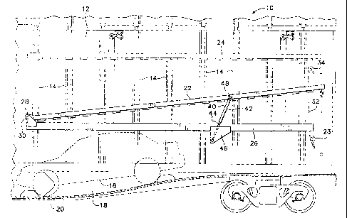
FIG. 1 is a partial side cutaway view of a
railroad car employing the lift assist mechanism of the
present invention.
FIG. 2 is a partial side cutaway view of the
lift assist mechanism shown in FIG. 1.
FIG. 3 is an end view taken along line 3-3 of
the lift assist mechanism of FIG. 2.
DETAILED DESCRIPTION OF THE PREFERRED EMBODIMENT
Referring to FIG. 1, a railroad car 10 includes
an interior side wall 12. Only one such side wall is
shown in the drawings and it should be understood that
the opposite side of the railroad car 10 has exactly the
same construction as will be described herein with
respect to the side wall 12. The side wall 12 is secured
to vertical posts 14 which line the inside of the
railroad car 10. Automobiles, such as automobile 16
(shown in phantom outline), are stored inside the
railroad car. Only one such automobile 16 is shown in
FIG. 1 and this automobile is stored inside a cargo well
18, the lower surface of which forms the floor 20 of the
railroad car 10.

CA 02354711 2001-08-03
4
FIG. 1 shows two decks 22 and 24. Deck 22 is a
moveable deck portion which is pivotally connected to a
horizontal support beam 26 by a pivot pin 28 which is
housed within a bracket 30 welded to the horizontal
support beam 26. The horizontal support beam 26 is, in
turn, secured to each of the vertical posts 14 by means
of bolts and the like (not shown).
The moveable deck portion 22 is raised and
lowered by means of a cable 32 looped over a pulley 34.
The cable 32 is controlled by a hand-cranked winch 36.
A spring loaded lift assist mechanism 40
comprises, preferably, an air cylinder 42 and a
reciprocating piston 44. The lift assist mechanism 40 is
coupled to a bracket 46 which is welded to the support
beam 26. An upper bracket 48 is welded to the moveable
deck 22 to receive the other end of the lift assist
mechanism 40.
Referring now to FIGS. 2 and 3, the bracket 46
includes a flange 50 which is welded to the underneath of
the support beam 26. The bracket 46 therefore extends
into an interior space that lies between the support
beams 26 and the vertical posts 14. In this way, the
lift assist mechanism is situated in what is otherwise
unused space inside the railroad car and does not
interfere with any other structure or cargo inside the
car. The bracket 46 comprises a pair of parallel plates
52 and 54 separated by cross plates 66 and 67 which are
welded to plates 52 and 54 to form a rigid unit.
The lift assist mechanism 40 is supported in
the bracket 46 on a centering spacer 56. A bolt 58
extends through the spacer S6 and is secured at the
opposite plate by a nut 60. The nut and bolt combination
extends through a slot 63 in the bracket 46. The slot 63
allows some leeway for connecting the lift assist
mechanism 40 during assembly. This is necessary because
the opposite end of the lift assist mechanism 40 is
affixed to an upper bracket 48 at a fixed point. The

CA 02354711 2001-08-03
slot 63 also permits the mechanism 40 to move as a unit
when the gas cylinder is fully extended. When this
occurs, the sudden change in weight on the winch crank
signals that the deck is fully raised. The gas cylinder
5 42 has an end that is secured to a pin 62 which is
coupled to the upper bracket 48. The upper bracket 48 is
welded to the moveable deck portion 22 at a point
approximately two-third's of the distance from the pivot
pin 28 to the forward end of the deck portion 22.
The lift assist mechanism is preferably a
pneumatic or gas spring. An example of the type of gas
spring suitable for this purpose is manufactured..~y
Industrial Gas Springs, Inc. of Newton Square,
Pennsylvania. The gas spring mechanism 40 provides a
lift assisting force as the moveable deck portion 22 is
raised by the winch 36. The winch 36 is adapted to be
hand-cranked.
As an alternative, other types of lift assist
devices may be used. For example, a mechanical spring
could be used in place of an gas spring or hybrids of
gas, air and mechanical spring combinations may also be
used.
The terms and expressions which have been
employed in the foregoing specification are used therein
as terms of description and not of limitation, and there
is no intention, in the use of such terms and
expressions, of excluding equivalents of the features
shown and described or portions thereof, it being
recognized that the scope of the invention is defined and
limited only by the claims which follow.

Representative Drawing
A single figure which represents the drawing illustrating the invention.
Administrative Status

2024-08-01:As part of the Next Generation Patents (NGP) transition, the Canadian Patents Database (CPD) now contains a more detailed Event History, which replicates the Event Log of our new back-office solution.

Please note that "Inactive:" events refers to events no longer in use in our new back-office solution.

For a clearer understanding of the status of the application/patent presented on this page, the site Disclaimer , as well as the definitions for Patent , Event History , Maintenance Fee  and Payment History  should be consulted.

Event History

Description Date
Time Limit for Reversal Expired 2011-08-03
Letter Sent 2010-08-03
Grant by Issuance 2007-02-06
Inactive: Cover page published 2007-02-05
Letter Sent 2006-12-13
Inactive: Final fee received 2006-11-20
Pre-grant 2006-11-20
Notice of Allowance is Issued 2006-07-13
Letter Sent 2006-07-13
Notice of Allowance is Issued 2006-07-13
Inactive: Approved for allowance (AFA) 2006-07-04
Inactive: IPC from MCD 2006-03-12
Amendment Received - Voluntary Amendment 2006-01-13
Inactive: S.30(2) Rules - Examiner requisition 2005-07-13
Amendment Received - Voluntary Amendment 2005-03-11
Inactive: S.30(2) Rules - Examiner requisition 2004-11-02
Amendment Received - Voluntary Amendment 2002-12-11
Amendment Received - Voluntary Amendment 2002-11-13
Letter Sent 2002-10-10
All Requirements for Examination Determined Compliant 2002-08-28
Request for Examination Requirements Determined Compliant 2002-08-28
Request for Examination Received 2002-08-28
Application Published (Open to Public Inspection) 2002-02-17
Inactive: Cover page published 2002-02-17
Inactive: First IPC assigned 2001-10-22
Inactive: Filing certificate - No RFE (English) 2001-08-28
Filing Requirements Determined Compliant 2001-08-28
Letter Sent 2001-08-28
Application Received - Regular National 2001-08-28

Abandonment History

There is no abandonment history.

Maintenance Fee

The last payment was received on 2006-07-21

Note : If the full payment has not been received on or before the date indicated, a further fee may be required which may be one of the following

  • the reinstatement fee;
  • the late payment fee; or
  • additional fee to reverse deemed expiry.

Please refer to the CIPO Patent Fees web page to see all current fee amounts.

Owners on Record

Note: Records showing the ownership history in alphabetical order.

Current Owners on Record
GUNDERSON LLC
Past Owners on Record
JAMES JARVIS
Past Owners that do not appear in the "Owners on Record" listing will appear in other documentation within the application.
Documents

To view selected files, please enter reCAPTCHA code :


To view images, click a link in the Document Description column. To download the documents, select one or more checkboxes in the first column and then click the "Download Selected in PDF format (Zip Archive)" or the "Download Selected as Single PDF" button.

List of published and non-published patent-specific documents on the CPD .

If you have any difficulty accessing content, you can call the Client Service Centre at 1-866-997-1936 or send them an e-mail at CIPO Client Service Centre.


Document
Description 
Date
(yyyy-mm-dd) 
Number of pages   Size of Image (KB) 
Representative drawing 2002-01-17 1 22
Drawings 2002-12-11 2 73
Claims 2001-08-03 2 67
Abstract 2001-08-03 1 20
Description 2001-08-03 5 264
Drawings 2001-08-03 2 79
Cover Page 2002-02-08 1 51
Description 2005-03-11 5 255
Claims 2006-01-13 2 63
Representative drawing 2007-01-16 1 25
Cover Page 2007-01-16 1 56
Courtesy - Certificate of registration (related document(s)) 2001-08-28 1 136
Filing Certificate (English) 2001-08-28 1 175
Acknowledgement of Request for Examination 2002-10-10 1 176
Reminder of maintenance fee due 2003-04-07 1 107
Commissioner's Notice - Application Found Allowable 2006-07-13 1 162
Maintenance Fee Notice 2010-09-14 1 170
Correspondence 2006-11-20 1 33