Language selection

Search

Patent 2354807 Summary

Third-party information liability

Some of the information on this Web page has been provided by external sources. The Government of Canada is not responsible for the accuracy, reliability or currency of the information supplied by external sources. Users wishing to rely upon this information should consult directly with the source of the information. Content provided by external sources is not subject to official languages, privacy and accessibility requirements.

Claims and Abstract availability

Any discrepancies in the text and image of the Claims and Abstract are due to differing posting times. Text of the Claims and Abstract are posted:

  • At the time the application is open to public inspection;
  • At the time of issue of the patent (grant).
(12) Patent Application: (11) CA 2354807
(54) English Title: MOTOR COOLING FAN BLADE ASSEMBLY WITH FINGER GUARD
(54) French Title: LAME DE VENTILATEUR DE REFROIDISSEMENT A MOTEUR AVEC PROTEGE-DOIGTS
Status: Deemed Abandoned and Beyond the Period of Reinstatement - Pending Response to Notice of Disregarded Communication
Bibliographic Data
(51) International Patent Classification (IPC):
  • F04D 29/18 (2006.01)
  • F04D 25/08 (2006.01)
  • F04D 29/32 (2006.01)
  • F04D 29/34 (2006.01)
  • H02K 9/04 (2006.01)
(72) Inventors :
  • GARLOCH, DUANE D. (United States of America)
  • WATERMAN, TIMOTHY J. (United States of America)
(73) Owners :
  • CARRIER CORPORATION
(71) Applicants :
  • CARRIER CORPORATION (United States of America)
(74) Agent: NORTON ROSE FULBRIGHT CANADA LLP/S.E.N.C.R.L., S.R.L.
(74) Associate agent:
(45) Issued:
(22) Filed Date: 2001-08-07
(41) Open to Public Inspection: 2002-02-28
Examination requested: 2001-08-07
Availability of licence: N/A
Dedicated to the Public: N/A
(25) Language of filing: English

Patent Cooperation Treaty (PCT): No

(30) Application Priority Data:
Application No. Country/Territory Date
09/652,745 (United States of America) 2000-08-31

Abstracts

English Abstract


A prop fan blade assembly for a draft inducer motor cooling fan used in a high
efficiency furnace includes rings concentric with and attached to an outer
blade guard.
Cooling air is drawn through the concentric rings by the fan and blown onto
the
motor. The rings function as a finger guard while producing a confined airflow
pattern which does not interfere with burner operation.


Claims

Note: Claims are shown in the official language in which they were submitted.

What is claimed is:
1. A prop fan blade assembly for a motor cooling fan, characterized by:
a hub having a centered hole therein for attachment to a fan shaft;
a plurality of fan blades attached to said hub, an outermost edge of each of
said
plurality of fan blades describing a first diameter around said fan shaft as
said fan
shaft and plurality of fan blades rotate;
an outer finger guard ring attached to said outermost edge of at least two of
said plurality of fan blades, said outer finger guard ring having a circular
shape;
at least one circular-shaped inner finger guard ring concentrically arranged
with said outer finger guard ring and attached to at least two of said
plurality of fan
blades; and
said outer finger guard ring and said at least one inner finger guard ring
being
disposed such that air drawn by said fan passes between said at least one
inner finger
guard ring and said outer finger guard ring before it passes between said
plurality of
fan blades.
2. A prop fan blade assembly according to claim 1 wherein an edge of said at
least
one inner finger guard ring is coplanar with an edge of said outer finger
guard ring.
3. A prop fan blade assembly according to claim 1, wherein said fan blade
assembly
is one-piece.
4. A prop fan blade assembly according to claim 3, wherein said fan blade
assembly
is plastic.
5. A prop fan blade assembly according to claim 1, wherein said at least one
inner
finger guard ring includes a notched portion in between each of said fan
blades.
6. A prop fan blade assembly according to claim 1, wherein said at least one
inner
finger guard ring is attached to each of said plurality of fan blades across
an entire
width of each fan blade.
-4-

7. A prop fan blade assembly according to claim 1, wherein said at least one
inner
finger guard ring is attached to each of said plurality of fan blades at a
leading edge of
each fan blade.
8. A prop fan blade assembly according to claim 1, wherein said at least one
inner
finger guard ring extends above and below said plurality of fan blades.
-5-

Description

Note: Descriptions are shown in the official language in which they were submitted.


CA 02354807 2001-08-07
r
MOTOR COOLING FAN BLADE ASSEMBLY WITH FINGER GUARD
This invention relates to the field of motor cooling fans, and in particular,
to a
fan blade assembly for a motor cooling fan used in a furnace.
Hot air furnaces have become more efficient over the years. Certain
improvements in heat exchangers, burner design, and combustion have increased
the
efficiency of furnaces, but these improvements frequently lead to the forced
redesign
of standard parts. One improvement that improves furnace efficiency is the
addition
of a draft inducer motor in the flue to create an induced draft. Such a motor
needs to
be cooled by a separate fan. The existing motor cooling fan for the draft
inducer
motor of a high efficiency furnace is deficient in that the fan throws air in
a wider
pattern than desired, sometimes interfering with proper burner operation. An
integral
finger guard in the form of a shroud in the existing motor, required for
safety
purposes, does not allow for controlling the discharge airflow pattern.
Briefly stated, a prop fan blade assembly for a draft inducer motor cooling
fan
used in a high efficiency furnace includes rings concentric with and attached
to an
outer blade guard. Cooling air is drawn through the concentric rings by the
fan and
blown onto the motor. The rings function as a finger guard while producing a
confined airflow pattern which does not interfere with burner operation.
According to an embodiment of the invention, a fan blade assembly for a
motor cooling fan includes a hub having a centered hole therein for attachment
to a
fan shaft a plurality of fan blades attached to the hub, an outermost edge of
each of the
plurality of fan blades describing a first diameter around the fan shaft as
the fan shaft
and plurality of fan blades rotate; an outer finger guard ring attached to the
outermost
edge of at least two of the plurality of fan blades, the outer finger guard
ring having a
circular shape; at least one circular-shaped inner finger guard ring
concentrically
arranged with the outer finger guard ring and attached to at least two of the
plurality
of fan blades; and the outer finger guard ring and the at least one inner
finger guard
ring being disposed such that air drawn by the fan passes between the at least
one
-1-

CA 02354807 2001-08-07
inner finger guard ring and the outer finger guard ring before it passes
between the
plurality of fan blades.
Fig. 1 shows a simplified schematic view of a draft inducer motor housing and
its relation to a burner assembly in a gas fiirnace.
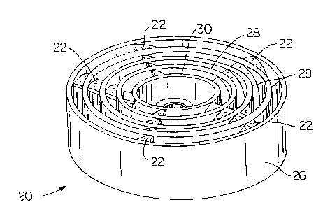
Fig. 2 shows a perspective view of the fan of the present invention.
Fig. 3 shows a top view of the fan of Fig. 2.
Fig. 4 shows a cross section view taken across the line 4-4 of Fig. 3.
Fig. 5 shows a second perspective view of the fan of the present invention.
Refernng to Fig. 1, in the prior art, a draft inducer motor 4 drives fan
blades 6
producing an airflow pattern that cools draft inducer motor 4 as shown by
arrows 8.
The air is blown partly toward a burner assembly 10. Burner assembly 10
includes a
gas orifice 12 which provides natural gas or propane gas to a burner 14. The
gas is
ignited producing a flame 16. As is readily seen, air from fan blades 6 can
interfere
with flame 16.
Referring to Figs. 2-3, a prop fan blade assembly 20 includes a plurality of
fan
blades 22 attached to a hub 24. Hub 24 includes a central hole 18 to permit
connection to a shaft of a fan motor (not shown). Fan blade assembly 20
fiuther
includes an outer finger guard ring 26 preferably attached to the outer tip of
each fan
blade 22. In addition, a plurality of inner finger guard rings 28, concentric
with outer
finger guard ring 26, are also attached to each fan blade 22. Rings 28 can
either be
attached to or near a leading edge 34 of fan blades 22 or be attached to the
entire
width of each fan blade 22 as shown in Fig. 5.
An extension 30 of hub 24 extends past the point on hub 24 that fan blades 22
attach to. Extension 30 provides additional strength to hub 24 and limits the
space
through which a finger or other piece could be inserted and contact fan blades
22. The
spacing between ring 26, rings 28, and hub extension 24 preferably meets UL
guidelines for protecting people from moving parts.
Referring to Fig. 4, the outer finger guard ring 26 and the inner finger guard
rings 28 are disposed such that air drawn by fan blade assembly 20 passes
between the
finger guard rings 26, 28 before it passes between fan blades 22. In the
preferred
-2-

CA 02354807 2001-08-07
1
embodiment, rings 28 are on the side of fan blades 22 in the direction the air
flow
comes from (upstream), while ring 26 extends a distance beyond fan blades 22
in the
direction downstream of the air flow, preferably so that a downstream edge 27
of ring
26 is even with a downstream end 25 of hub 24. Rings 26, 28 are optionally on
both
sides of fan blades 22.
The edges of rings 26, 28 in the upstream the air flow direction are in the
same
plane if the fan blades 22 are substantially perpendicular to the fan motor
shaft, but if
the fan blades 22 are angled or curved in the upstream direction as shown in
Fig. 5,
the heights of rings 28 are preferably the same, resulting in the upstream
edges of ring
26 some of rings 28, and ring 30 being at different levels as measured from
downstream end 25 of hub 24.
Referring also to Fig. 5, a plurality of notches 32 are in rings 28, extending
from a trailing edge 35 of one fan blade 22 to the leading edge 34 of the next
fan
blade 22. Since the leading edges 34 are not in the same plane as the trailing
edges 35
due to the angle of the fan blades 22 to the plane normal to the rotating fan
shaft (not
shown), the distance, as measured in the direction of the axis of the fan
shaft, between
the leading edge 34 and the trailing edge 35, measured at each ring, becomes
the
vertical distance of each notch 32. The horizontal distance of each notch is
preferably
equal to the distance between fan blades 22. In other words, since there is
full contact
between each ring 28 and each fan blade 22 along the width (in the direction
of
rotation) of the fan blade, each ring 28 is higher (in the axial direction of
the fan shaft)
at the trailing edge 35 than at the leading edge 34 of each fan blade 22. Each
notch 32
in each ring 28 brings the lower edge (closer to the downstream end 25 of hub
24) of
ring 28 from the level of trailing edge 35 of one fan blade 22 to the level of
leading
edge 34 of the next fan blade 22. The notches 32 as shown in the figures
provides
additional air flow not present if notches 32 are absent.
Although fan blade assembly 20 can be constructed by attaching its
component pieces using an adhesive or welding/brazing, depending on whether
the
fan material is wood, plastic, or metal, in the preferred embodiment, fan
blade
assembly 20 is one-piece plastic, such as VALOX 310-SEO unreinforced PBT
polyester plastic.
-3-

Representative Drawing
A single figure which represents the drawing illustrating the invention.
Administrative Status

2024-08-01:As part of the Next Generation Patents (NGP) transition, the Canadian Patents Database (CPD) now contains a more detailed Event History, which replicates the Event Log of our new back-office solution.

Please note that "Inactive:" events refers to events no longer in use in our new back-office solution.

For a clearer understanding of the status of the application/patent presented on this page, the site Disclaimer , as well as the definitions for Patent , Event History , Maintenance Fee  and Payment History  should be consulted.

Event History

Description Date
Application Not Reinstated by Deadline 2007-08-07
Time Limit for Reversal Expired 2007-08-07
Deemed Abandoned - Failure to Respond to Maintenance Fee Notice 2006-08-07
Amendment Received - Voluntary Amendment 2006-07-19
Inactive: IPC from MCD 2006-03-12
Inactive: S.30(2) Rules - Examiner requisition 2006-01-30
Amendment Received - Voluntary Amendment 2005-06-29
Inactive: S.29 Rules - Examiner requisition 2005-01-06
Inactive: S.30(2) Rules - Examiner requisition 2005-01-06
Amendment Received - Voluntary Amendment 2004-10-18
Inactive: S.30(2) Rules - Examiner requisition 2004-04-16
Inactive: S.29 Rules - Examiner requisition 2004-04-16
Letter Sent 2003-08-25
Revocation of Agent Requirements Determined Compliant 2003-03-25
Inactive: Office letter 2003-03-25
Appointment of Agent Requirements Determined Compliant 2003-03-25
Appointment of Agent Request 2003-03-14
Revocation of Agent Request 2003-03-14
Application Published (Open to Public Inspection) 2002-02-28
Inactive: Cover page published 2002-02-27
Inactive: First IPC assigned 2001-10-23
Inactive: Filing certificate - RFE (English) 2001-08-28
Filing Requirements Determined Compliant 2001-08-28
Letter Sent 2001-08-28
Application Received - Regular National 2001-08-28
Request for Examination Requirements Determined Compliant 2001-08-07
All Requirements for Examination Determined Compliant 2001-08-07

Abandonment History

Abandonment Date Reason Reinstatement Date
2006-08-07

Maintenance Fee

The last payment was received on 2005-08-08

Note : If the full payment has not been received on or before the date indicated, a further fee may be required which may be one of the following

  • the reinstatement fee;
  • the late payment fee; or
  • additional fee to reverse deemed expiry.

Please refer to the CIPO Patent Fees web page to see all current fee amounts.

Fee History

Fee Type Anniversary Year Due Date Paid Date
Request for examination - standard 2001-08-07
Registration of a document 2001-08-07
Application fee - standard 2001-08-07
MF (application, 3rd anniv.) - standard 03 2004-08-09 2003-07-30
MF (application, 2nd anniv.) - standard 02 2003-08-07 2003-08-06
MF (application, 4th anniv.) - standard 04 2005-08-08 2005-08-08
Owners on Record

Note: Records showing the ownership history in alphabetical order.

Current Owners on Record
CARRIER CORPORATION
Past Owners on Record
DUANE D. GARLOCH
TIMOTHY J. WATERMAN
Past Owners that do not appear in the "Owners on Record" listing will appear in other documentation within the application.
Documents

To view selected files, please enter reCAPTCHA code :


To view images, click a link in the Document Description column. To download the documents, select one or more checkboxes in the first column and then click the "Download Selected in PDF format (Zip Archive)" or the "Download Selected as Single PDF" button.

List of published and non-published patent-specific documents on the CPD .

If you have any difficulty accessing content, you can call the Client Service Centre at 1-866-997-1936 or send them an e-mail at CIPO Client Service Centre.


Document
Description 
Date
(yyyy-mm-dd) 
Number of pages   Size of Image (KB) 
Representative drawing 2002-01-18 1 17
Abstract 2001-08-07 1 11
Description 2001-08-07 3 161
Claims 2001-08-07 2 50
Drawings 2001-08-07 3 86
Cover Page 2002-02-22 1 42
Description 2004-10-18 3 166
Claims 2004-10-18 2 51
Drawings 2004-10-18 3 86
Description 2005-06-29 3 165
Claims 2005-06-29 2 49
Claims 2006-07-19 2 49
Courtesy - Certificate of registration (related document(s)) 2001-08-28 1 136
Filing Certificate (English) 2001-08-28 1 175
Reminder of maintenance fee due 2003-04-08 1 107
Courtesy - Abandonment Letter (Maintenance Fee) 2006-10-02 1 175
Correspondence 2003-03-14 3 92
Correspondence 2003-03-25 1 14
Correspondence 2003-03-25 1 16
Correspondence 2003-08-25 1 17