Note: Descriptions are shown in the official language in which they were submitted.
CA 02355013 2001-08-13
METHOD FOR PRODUCTION OF CATALYST
BACKGROUND OF THE INVENTION
Field of the Invention:
This invention relates to a method for producing a
catalyst. More specifically, it relates to a method for
producing a catalyst which comprises controlling the liquid
level of the top face of a monolithic carrier by an
image-processing sensor, especially a method for producing
an exhaust gas purifying catalyst.
Description of Related Art:
In the deposition of a catalytically active component
on a monolithic carrier, when the expensive active component
is deposited also on the lateral face of the carrier, such
lateral face so deposited does not treat exhaust gases and
it rather brings the disadvantage of heightening the price
of produced catalysts. Thus, it is required a method for not
depositing or adhering the active component to the lateral
face.
In this method, a slurry containing the active component
is raised from the bottom face of carrier into the cells,
and after the slurry has reached the top face of the carrier,
the slurry in the cells is discharged from the lower side
in a state not overflowing the top face. For preventing the
slurry from overflowing the top face, it may cite a visual
observation. It may use a laser or supersonic sensor in
consideration of productivity.
The method using such a sensor, however, has the problem
of not satisfactorily corresponding to variations in the
viscosity and the speed of forced penetration of the slurry
because it is incapable of confirming the position of the
- 1 -
CA 02355013 2004-06-04
slurry with accuracy till the slurry reaches the top
face, and capable of detecting the liquid level only
after the slurry has surpassed the top face. Thus, in
order to coat the slurry to the carrier completely, it
has entailed the problem of suffering the slurry to
overflow the top face and come to adhere to the lateral
face and the device being used for the deposition.
SUMMARY OF THE INVENTION
We have pursued a diligent study of a method capable
of accurately detecting the liquid level of the slurry at
the proximity of the top face of the carrier while the
slurry is ascending in the interior of the carrier, and
have found that the position of liquid level of the
slurry can be accurately detected by an image-processing
sensor using a charge coupled device (CCD) camera. This
invention has been perfected as a result.
In accordance with one aspect of the present
invention, there is provided a method for the production
of a catalyst, which comprises introducing a liquid
substance containing a catalytic component into a
monolithic carrier from the bottom face thereof; and
detecting the liquid level near or at the top face of the
carrier by an image-processing sensor placed above the
carrier.
According to the present invention, it can eliminate
the problems of the conventional method such as the
adhesion of the liquid substance overflowing the top face
of the carrier to the lateral face and the device being
used for the deposition and the consequent loss of the
expensive liquid substance and spotting of the carrier
and device used. It also permits a saving in the cost of
2
CA 02355013 2004-06-04
production by ensuring safety of coating and decreasing
the loss of liquid substances.
The above and other objects, features and advantages
2a
CA 02355013 2001-08-13
of the present invention will become clear from the following
description of the preferred embodiments.
BRIEF DESCRIPTION OF DRAWINGS
The accompanying drawing incorporated in and forming
a part of the specification, illustrates several aspects of
the present invention, and together with the description serve
to explain the principles of the invention. In the drawings:
Fig. 1 is a partial cross section intended to describe
the retain of a monolithic carrier in the case of deposition;
Fig. 2 is a partial cross section of the impregnating
device for depositing a slurry on a carrier;
Fig. 3 is another partial cross section of the
impregnating device; and
Fig. 4 is a partial cross section of yet another example
of the impregnating device.
DETAILED DESCRIPTION OF THE PREFERRED EMBODIMENTS
Now, this invention will be described in detail below.
The monolithic carrier to be used in this invention is
not restricted but required to be a ref ractory structure having
a plurality of cells penetrate through the interior thereof.
Monolithic honeycomb carriers and metal honeycomb carriers
may be cited as examples.
The monolithic carriers which are usable herein
generally include honeycomb carriers using cordierite,
mullite, CY-alumina, zirconia, titania, titanium phosphate,
aluminum titanate, alumino silicate, and magnesium silicate
as raw materials and integral structures using such
heat-resistant metals as stainless steel and Fe-Cr-Al alloys,
for example.
The monolithic carrier is produced by a method of
- 3 -
CA 02355013 2001-08-13
extrusion molding, or reeling a sheet like element into a
roll, or the like. The shape of the gas passages in the
monolithic carrier (the shape of cells) may be hexagon,
tetragon, triangle, or corrugation whichever best suits the
occasion. The cell density {the number of cells per unit cross
section, 6.45 cm2 (1 square inch )} is generally in the range
of 100 to 1500 cells, though variable with the kinds of exhaust
gas such as unburnt hydrocarbon, carbon monoxide, and nitrogen
oxides which occur in tunnels or emanate from plants and
internal combustion engines such as automobile engines and
diesel engines. Incidentally, the visible shape of the
carrier is not discriminated but may be a triangle, circular,
elliptic, or rectangular cross section.
The monolithic carrier is put to use as coated in advance
with a refractory inorganic oxide or as simultaneously coated
with such an inorganic oxide and a catalytic component
effective in treating an exhaust gas. This invention
designates such inorganic oxide, catalytically active
component, and mixture thereof as a"catalytic component."
Examples of the refractory inorganic oxide may include y,
(5, 77, and 0 activated alumina, ceriumoxide, zirconiumoxide,
tungsten oxide, titanium oxide, silicon oxide, zeolite,
alkaline earth elements, and complex oxides thereof. The
catalytic component is not particularly discriminated but
required to be capable of disposing of harmful substances
in the exhaust gas. Examples of the catalytic component may
include noble metals such as rhodium, platinum, and palladium,
base metals such as manganese, cobalt, chromium, nickel, and
iron, and mixtures thereof.
The catalytic component is treated by a known method
such as a mill into slurry and then deposited on a monolithic
carrier. The slurry, which is usable in this invention, is
- 4 -
CA 02355013 2001-08-13
not restricted but required to be capable of ascending the
interiors of the cells. The slurry can be produced for example
by treating an inorganic oxide such as an alumina powder with
an aqueous inorganic or organic acid solution or by treating
an inorganic oxide such as alumina and a catalytic component
such as the salt of platinum with an aqueous inorganic or
organic acid solution. The liquid substance, which is used
in this invention, embraces the aqueous solution of a catalytic
component besides the slurry mentioned above.
Further, this invention embraces also multilayer coating.
The term"multilayer coating" as used herein means depositing
coats of one same kind or different kinds in a multiple steps.
In highly refractory and high performance catalysts,
catalysts having a plurality of coats such as two are usual.
Now, this invention will be described below with the
drawings attached hereto.
Fig. 1 is a partial cross section intended to describe
the retention of a carrier. The method will be described with
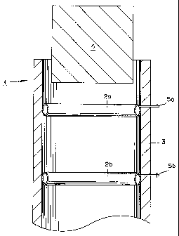
a cylindrical carrier as a typical example. In Fig. 1, a hol low
frame 3 of a shape permitting insertion therein of a carrier
4 is prepared in advance and provided on the inner face thereof
with at least one retainer 2 (two in Fig. 1) shaped like a
swimming ring that is able to press the carrier 4 from the
lateral side thereof.
For the purpose of impregnating the carrier 4 with slurry
(not shown), the retainer 2 like a swimming ring retains the
carrier 4 and seals the lateral side of the carrier as well.
The retainer 2 is made of an elastic material such as rubber
or plastic or soft plastic because it is inflated by inserting
a gas such as air and consequently enabled to retain the carrier
4. The gas is admitted into this retainer via a nozzle 5 that
is disposed on the outer face of the retainer 2. Optionally,
- 5 -
CA 02355013 2001-08-13
the retainer may be used at one point in the bottom face.
Though the internal shape of the hollow frame 3 is not
restricted but required to permit insertion therein of the
carrier, it is preferred to bear similarity with the outer
shape of the carrier. Specifically, when the carrier has a
circular outer shape, the inner face of the frame is also
a circular shape. The reason for constructing the flame as
described above is that when the retainer 2 is inflated, it
will uniformly hold the whole of the lateral face of the carrier
4 and seal the lateral face thereof as well.
The carrier 4 is inserted into the interior of an
impregnating device 1 from the above portion thereof. When
the carrier 4 reaches a position with the bottom face of the
retainer 2b, this motion is stopped. Then, the carrier 4 is
fixed by inflating the retainer 2b. The retainer 2b so
inflated is retained in the inflated state. Thereafter, with
respect to the top face of the carrier, the retainer 2a is
also inflated and fixed in the inflated state. Consequently,
the carrier is fixed in the impregnating device.
Now, the method for depositing the carrier with a slurry
as a typical example will be described below. Fig. 2 is a
partial cross section illustrating one example of the
impregnating device serving to deposit a slurry on a carrier.
In Fig. 2, a slurry 26 held inside a hollow frame 23 is ascended
in the interior of the frame 23 by the action of a known liquid
delivering device of the shape of a piston (not shown). The
ascent of the slurry 26 in the interior of a monolithic carrier
24 is monitored and detected from above the carrier with an
image-processing sensor 27. The image sensor 27 is positioned
above the monolithic carrier. Commendably, the distance of
this sensor 27 from the carrier is suitably decided in
consideration of factors such as the precision of the image
- 6 -
CA 02355013 2001-08-13
sensor 27 and the color of the slurry.
The image sensor 27 is set as follows. The monolithic
carrier 24 is set in an impregnating device 21. The color
of the carrier 24 is extracted by the image sensor (CCD camera)
27. The "image (processing) sensor" 27 means a sensor that
extracts the color by setting a relevant range based on a
color image signal from the camera and then judging the
coincidence of a designated color on an image plane. The
designated color (such as of the carrier), for example, has
the number of picture elements of the designated color
decreased when a different color (such as of the slurry) is
appeared therein. The ascent of liquid level can be detected
by the change of the number of picture elements. The white
of carrier is extracted as the designated color, for example.
In the multilayer coated catalyst, the color of the catalyst
deposited in the immediately preceding step is tobe extracted.
In that case, a certain number of picture elements are measured
in the range of 100,000 to 300,000, for example, though
depending on the quality of CCD camera in use. Since any sort
of slurry differs in color from the carrier, when the slurry
is reached toward the proximity of the top face of the carrier,
a color different from the extracted color develops on the
image plane of the camera. When such a different color appears
on the image plane, the number of picture elements of the
extracted color in advance comes to be decreased. Thisdecline
permits detection of the ascent of the slurry to the proximity
of the top face of the carrier. The expression "the proximity
of the top face of the carrier" as used herein refers to the
range embracing the top face of the carrier and the interior
of the carrier and allowing detection by the image sensor.
The range detectable by the image sensor is variable
with the cell density and cross section of carrier, the quality
- 7 -
CA 02355013 2001-08-13
and lens of CCD camera, and the precision of image sensor.
Though the stopping position of the slurry at the top face
is not easily set in advance because it is affected by the
viscosity of slurry and the speed of ascent of slurry, it
is possible by the image sensor to detect the slurry at the
proximity of the top face and brings the slurry to stop at
the top face without suffering the slurry from overflowing
the top face.
Further, since the image sensor 27 is capable of detecting
the slurry not only at the proximity of the top face of the
carrier 24 but also in the interiors of the cells, it is possible
to detect the liquid level of the slurry 26 in the interiors
of the cells. It is, consequently, possible either to coat
the carrier 24 completely as far as the top face with the
slurry 26 or leave quantitatively the undeposited part to
a certain degree in the vicinity of the top face.
The position at which the CCD camera is set may be directly
above or oblique relative to the top face of the carrier 24
so long as the detection can be attained.
The site of the production of the carrier may be furnished
with an illuminating device. The kind, quantity, and position
of installation thereof are not restricted so long as they
do not affect the detection by the image sensor.
Since the use of the image sensor 27 permits the position
of the slurry 26 to be accurately detected, the slurry can
be stopped without overflowing the top face of the carrier
24. After coating has been completed up to the top face,
aspirating the excess slurry fromthe bottom face of the carrier
or expelling the excess slurry by blowing a gas from above
the carrier terminates it.
The series of steps mentioned above may be performed
either individually or continuously automatically,
- 8 -
CA 02355013 2001-08-13
The carrier is removed from the impregnating device after
the gas filled in the retainer has been withdrawn. Then, the
removed carrier is dried and optionally calcined to complete
a catalyst.
Fig. 3 is another partial cross section of the
impregnating device for depositing the slurry on the carrier.
In Fig. 3, a slurry 36 is ascended in the interior of a hollow
frame 33 made of a hard resin 33 by a known liquid-delivering
device of the type of piston (not shown). When the slurry
36 so ascending happens to leak between the carrier 34 and
the frame 33, the leaking slurry 36 is at a disadvantage in
adhering to the carrier 34 and the frame 33 and inducing a
loss of the expensive slurry. To avoid this leakage, a
retainer 38 made of an elastic substance such as rubber or
plastic or soft plastic is used to seal tightly the gap between
the carrier 34 and the frame 33 and prevent the slurry 36
from leaking to the exterior.
The slurry is deposited on the carrier by controlling
the liquid level using the image sensor 37. The carrier coated
with the slurry is dried and optionally calcined to complete
a catalyst.
Fig. 4 is a partial cross section of yet another example
of the impregnating device for depositing the slurry on the
carrier. In Fig. 4, since a carrier retainer 48 made of an
elastic substance such as rubber or plastic or soft plastic
retains a carrier 44, the carrier 44 can be retained in intimate
contact with the retainer 48. If the slurry 46 has ascended
to the site of this intimate contact, this slurry 46 will
not leak from the gap between the carrier 44 and the retainer
48. Thus the slurry 46 that contains an expensive material
can be used or reused without incurring any loss.
The carrier retainer 48 is fixed to a frame 43 made of
- 9 -
CA 02355013 2001-08-13
a material such as stainless steel, which is incapable of
inducing an interaction with the slurry. Since the top of
the frame 43 falls below the retainer 48, it is enabled to
retain the carrier 44. The top shape of the frame 43 is not
restricted but required to be capable of retaining the carrier
and causing the slurry to flow inwardly. It may be inclined
inwardly, for example.
The slurry 46 is ascended in the interior of the retainer
48 by a known liquid-delivering device such as a piston (not
shown).
The slurry is deposited on the carrier by controlling
the liquid level using the image sensor 47. The carrier coated
with the slurry is dried and optionally calcined to complete
a catalyst.
The devices for retaining and impregnating the carrier
may be selected from among known devices except for the image
sensor.
Methods for depositing the slurry on the carrier
automatically by controlling the liquid level with the image
sensor are embraced in the scope of this invention.
EXAMPLES
Now, this invention will be specif ically described below
with the examples. It should be noted that this invention
is not limited to these examples.
EXAMPLE 1
A monolithic carrier (400 cpsi/6 mil, available from
Denso K.K. in Japan) was set in an impregnating device
illustrated in Fig. 2. A CCD camera set above the carrier
was used to extract the white part of the carrier. The number
of picture elements was 100,000 to 120,000.
- 10 -
CA 02355013 2001-08-13
Then, a slurry containing a Pd type catalytic component
was forcibly introduced into the carrier from the bottom face
thereof. This slurry had a specific gravity of 1.600 g/ml
and a viscosity of 500 cps. The flow velocity of the slurry
being introduced was 3,000 L/hr.- The system was set so as
to stop the introduction of the slurry when the blown slurry
ascended at the proximity of the top face of the carrier,
the number of picture elements of the extracted white decreased,
and the number surpassed 1,000. This is termed as a tolerance
1,000 in the number of picture elements. The system could
be stopped without suffering the slurry to overflow the top
face of the carrier and adhere to the lateral face thereof.
At this time, the slurry is completely coated to the
top face without overflow on the lateral face.
EXAMPLE 2
The procedure of Example 1 was repeated except that the
flow velocity of the slurry was changed to 2,800 L/hr. At
this time, the top face of the carrier was coated with the
slurry except for the two cells next to the outermost periphery.
EXAMPLE 3
The procedure of Example 1 was repeated except that the
flow velocity of the slurry was changed to 1, 000 L/hr. A size
of about 5 mm from the top face of the carrier was left uncoated
with the slurry.
EXAMPLE 4
The procedure of Example 1 was repeated except that the
viscosity of the slurry was changed to 1,000 cps. A size of
about 5 mm from the top face of the carrier was left uncoated
with the slurry.
- 11 -
CA 02355013 2001-08-13
EXAMPLE 5
The procedure of Example 1 was repeated except that the
tolerance was changed to 60,000. A size of about 5 mm from
the top face of the carrier was left uncoated with the slurry.
EXAMPLE 6
The catalyst prepared in Example 1 was set in the device
illustrated in Fig. 2. The brown portion of the prepared
catalyst was extracted by the CCD camera set above the catalyst.
The number of picture elements was 150,000 to 170,000.
Then, a slurry containing a Rh type catalytic component
was introduced into the carrier with force from the bottom
face of the carrier. This slurry had a specific gravity of
1.300 g/ml and a viscosity of 150 cps. The flow velocity of
the slurry during the introduction was 2,500 L/hr.
The system was so set as to stop the introduction of
the slurry when the yellowish white slurry ascended at the
proximity of the top face of the catalyst, the number of picture
elements of the extracted brown was declined, and the number
fell below 10,000.
As a result, the systemcouldbe stoppedwithout suffering
the slurry to overflow the top face of the catalyst and adhere
to the lateral face. At this time, the top face of the catalyst
was coated with the slurry except for three cells next to
the outermost periphery.
COMPARATIVE EXAMPLE
A monolithic carrier ( supra ) was set in an impregnating
device.
Then, a slurry containing a Pd type catalytic component
was introduced into the carrier with force from the bottom
- 12 -
CA 02355013 2006-09-29
face thereof. This slurry had a specific gravity of 1.600
g/ml and a viscosity of 500 cps. The flow velocity of the
slurry during the introduction was 3,000 L/hr.
The liquid level of the slurry was detected with a laser
sensor. Since the laser sensor only could detect-the liquid
level after the slurry had surpassed the top face of the carrier,
the slurry overflowed and adhered to the lateral face of the
carrier.
As demonstrated above, this invention is to control the
position for stopping the liquid level, the uncoated portion
of the carrier, and the overflow by optimizing conditions
such as the tolerance of CCD camera in the number of picture
elements, the viscosity of slurry, and the flow velocity of
slurry by force, while the conventional laser sensor was
incapable of controlling the position for stopping the liquid
level of the slurry.
It is possible to ef fect the deposition with high accuracy
without inducing excess adhesion to the lateral face of the
carrier by combining the image sensor and the retainer.
- 13 -