Note: Descriptions are shown in the official language in which they were submitted.
CA 02355670 2001-06-15
WO 00/37279 PCT/IJS99/30426
SYSTEM. METHOD AND APPARATUS FOR CONNECTING
ELECTRICAL SOURCES IN SERIES UNDER FULL LOAD
BACKGROUND
Field of the Invention
The present invention is related to a system, method and apparatus for
connecting a low-voltage high-current DC source (P~) when additional power
is required by the load. The invention enables the series connection to be
made under full power and, in a preferred embodiment, doubles the current
rating of the first source Po.
In the preferred embodiment, the invention doubles the current rating of
~. the-low-current high-voltage source Pp by breaking it into two series
sources
and reconfiguring them to operate in parallel. The output voltage of Po in
parallel mode is only half its series value but this is compensated for by the
addition of the series connected high-current low-voltage source P~. An
important feature of this invention is that it enables the second source P~ to
be
connected in series with the first source Pp while under full power seamlessly
and without appreciably dropping the flow of power to the load or raising the
voltage of the load while operating within the rating constraints of the first
and
second sources Pp, P~ such that the power transfer is transparent to the load,
i.e., no anamolies in power (current or voltage interruptions, spikes,
oscillations, drop-aff, perturbations, etc.) are sensed by the load. This is
achieved by using the second source P~ to commutate the load current. The
resulting circuit topology allows the load current to be increased to its
limit
with both sources contributing power at their rated limits. A further feature
of
this invention is the control strategy used to control the source P~ and
effect
the transitions between modes.
The Problem Solved by this Invention
CA 02355670 2001-06-15
WO 00/37279 PCT/US99/30426
In a typical application of the present invention, an electrical load is
supplied by a diesel engine driving a three phase, single-winding alternator
connected to a diode rectifier. The alternator/rectifier combination is
constrained by current and voltage ratings based on the rated engine power
at full rpm. In this case, the load is generally operated at constant DC
voltage
with power varying in proportion to the DC input current. This mode of
operation is herein referred to as Diesel Operation (Figure 1 ).
It is desirable to operate the load at higher power by connecting a
second high-current power source in series with the output of the rectifier.
The second source, which is constrained at about half the rated load voltage,
must be switched in while the load is operating at full diesel power and,
furthermore, must not raise the load voltage.
The problem, therefore, is to find an economically viable circuit
topology and control strategy to connect a low-voltage high-current power
source P~ in series with a high-voltage low-current power source Po that is
operating an electrical load. The circuit must double the current rating of
Po,
not increase the load voltage, and allow for smooth connection of the second
source P! at times when increased load current is required for higher power
operation.
Approaches to Supply More Current to the Load at Rated Voltage
Additional current is available to operate the load at higher power if an
external DC source is connected in parallel with the output of the rectifier
(Figure 2). When the voltage of the external source is greater than the output
of the rectifier, the rectifier diodes become reverse biased, the load current
transfers from the alternator to the external source and, as a result, the
alternator/rectifier current decreases to zero. This type of Parallel Line
Connection allows an external source to supply the additional current and
power at the rated voltage of the load. The connection can be made while the
2
CA 02355670 2001-06-15
_ WO 00!37279 PCT/US99/30426
load is operating at full diesel power but the voltage of the external source
must equal the required voltage of the load.
If the voltage of the external source is lower than the rated load
voltage, the source can be connected in series with the rectifier to provide
additional power while maintaining the required load voltage (Figure 3). In
this type of series line connection, the alternator is operated at a reduced
voltage so that the resulting load voltage remains at its rated valued. The
rectifier and external source each carry the full load current but they
contribute
power proportional to their respective voltages. This mode is also referred to
herein as Diesel Boost Operation since the voltage of the external power
source is boosted by the diesel/alternatorlrectifier combination to supply the
load at its rated voltage and with higher power.
Disadvanta4es of these Aaproaches
The use of a parallel line connection is limited to cases where the
voitage of the external source is equal to the required operating voltage of
the
load.
The use of a series line connection has two serious problems. The first
is that the alternator and rectifier must be oversized to handle the increased
load current even though they operate at less than rated voltage while in
series mode. For example, if the load power is doubled during Diesel Boost
Operation and the external source supplies half the load voltage, then the
alternator and rectifier must carry twice their rated current at half their
rated
voltage. White the alternator's output power remains essentially the same as
in Diesel Mode, the losses due to the high currents are prohibitive and this
mode of operation is only possible for a very short time.
The second problem is that there is considerable difficulty in switching
from Diesel Operation to Series Line Operation without shutting off (i.e.,
interrupting) power to the load. The required load transfer must be rapid and
3
~
CA 02355670 2004-O1-26
without any power interruptions in the load. There is no economical method to
accomplish the required commutation process with a simple series line
connection.
An approach to supply more current to the load may be to reconfigure
the alternator windings into two parallel sets of windings (forming a dual
winding alternator) and connecting the windings to two rectifiers. However,
there are no known means heretofore to simultaneously maintain the load at
its rated voltage (without drop aff, perturbations, etc.) with two parallel
connected rectifiers.
In summary, a parallel line connection will not work when the voltage of
the available external source is less than the rated voltage of the load. A
series line connection is not practical because the size of the alternator and
rectifier have to be increased to handle the higher currents and there is no
feasible way to make the connection while under power. A dual winding
alternator with two parallel connected rectifiers will not work because the
output voltage is too low for the load.
Heretofore, there has been no means for resolving the foregoing
problems.
SUMMARY AND OBJECTS OF THE INVENTION
The present invention overcomes the drawbacks mentioned above by
providing a low-voltage/high-current source P~ to supply additional power to a
high voltage load without appreciably dropping the flow of power to the load
or
raising the voltage of the toad while operating within the rating constraints
of
the first and second sources Po, P~ such that the power transfer is seamless,
i.e., transparent to the load, i.e., no anamolies in power (current or voltage
interruptions, spikes, osc~tations, drop-off, perturbations, etc.) are sensed
by
the load.
In one embodiment, the invention doubles the current rating of a high-
voltage low-current source Pp, allowing it to operate virtually indefinitely
(i.e.,
4
CA 02355670 2001-06-15
WO 00/37279 PCT/US99/30426
extended periods of time) at increased currents required by a series
connection with a low-voltage high-current source P~.
The present invention further provides the second source P~ to be
connected (and disconnected) in series with the first source Pp while the load
is operating under full power.
The resulting circuit topology and control strategy overcomes the
disadvantages of both the parallel and series line connections that previously
rendered them unsuitable for this application. This invention makes it
possible to add a high-current source in series with an operating low-current
source and increase the load current to its limit.
BRIEF DESCRIPTION OF THE PREFERRED EMBODIMENT
Fig. 1 shows the diesel operation;
Fig. 2 shows the parallel line connection;
Fig. 3 shows the simple series line connection;
Fig. 4 shows the series line connection with parallel rectifiers;
Fig. 5 shows the present invention capable of full load power transfer;
Fig. 6 shows the present invention optimized for fewer components;
Fig. 7 shows the present invention in dual mode;
Fig. 8 shows the flow chart for the connect sequence of the present
invention;
Fig. 9 shows the flow chart for the disconnect sequence the present
invention; and
CA 02355670 2001-06-15
WO 00/37279 PCT/US99/30426
Fig. 10 shows the diesel powered AC haul truck with the dual mode
diesel boost trolley configuration or the present invention.
DETAILED DESCRIPTION OF THE PREFERRED EMBODIMENTS
The invention is preferably explained by considering the solution in two
parts. However, it will be appreciated that the form of explanation shall not
limit the scope of the invention as claimed and that the invention may be
explained or practiced otherwise.
Part I - Use of a Dual Winding Alternator and a Second Rectifier to Double
the Current Rating
The solution to the problem of high alternator/rectifier currents during
series operation is to use a dual winding alternator and two rectifiers as
illustrated in Figure 4. In this instance, the alternator is configured with
two
star windings and the resulting six outputs are connected to two separate
diode rectifiers. In the preferred embodiment, each winding has the same
rated current and one-half the rated voltage as the single winding alternator.
Of course, other configurations are possible in the present invention. For
example, it is possible to configure three star windings with nine outputs
connected to three separate rectifiers.
The outputs of the two rectifiers can be connected in series to supply
the rated current and voltage to the load. The addition of the second
rectifier
is not obvious because the additional rectifier slightly reduces the overall
system efficiency, but this is acceptable especially for the particular
application of the present invention. An advantage revealed by the present
invention is that with the use of each additional rectifier the voltage rating
of
each rectifier may be reduced because the series connection reduces the
blocking voltage requirement on each rectifier.
This series configuration, for example, is suitable for normal Diesel
Operation when the load power can be met by the diesel engine and the full
6
CA 02355670 2001-06-15
WO 00/37279 PCT/US99/30426
load voltage must be supplied by the alternatoNrectifier combination. In this
mode, the alternator windings and rectifier are at the same current levels
that
they would be for a single winding/single rectifier solution. Advantageously,
the voltage and flux levels in the alternator are unchanged.
The outputs of the two rectifiers can be connected in parallel to supply,
in the preferred embodiment, twice the rated current at half the rated
voltage.
This configuration is suitable for Diesel Boost Operation when the alternator
and rectifier must handle much higher currents at a greatly reduced voltage.
Here again, the alternator windings and rectifiers operate at the same current
level as for the single winding case, but in this case, the parallel
configuration
doubles the output current.
The use of a dual winding alternator with two rectifiers that can be
connected in either series or parallel solves the problem of excessively high
alternator and rectifier currents. The series connection provides rated
voltage
under Diesel Operation and the parallel connection doubles the output current
capability. Hence, the present invention resolves the previous problems
seamlessly and without appreciably dropping the flow of power to the load or
raising the voltage of the load while operating within the rating constraints
of
the first and second sources Po, P~ such that the power transfer is
transparent
to the load, i.e., no anamolies in power (current or voltage interruptions,
spikes, oscillations, drop-off, perturbations, etc.) are sensed by the load.
The use of a dual winding alternator with two rectifiers that can be
configured in either series or parallel may be applied to various
applications.
Although the present invention is explained below with reference to a diesel
engine trolley, the invention may be applied, for example, to locomotives
where the available power is limited, high current is required at low voltage,
and high voltage is required at low current, corresponding to low speed and
high speed operation, respectively. A distinguishing feature of this invention
is that the dual winding alternator with two rectifiers is used to facilitate
smooth series-to-parallel and parallel-to-series transitions particularly
while
under full load and while maintaining full load voltage.
7
CA 02355670 2001-06-15
WO 00/37279 PCT/US99/30426
In the preferred embodiment, a voltage source inverter (VSI) is used as
the load to facilitate this smooth transition. The VSI incorporates a
capacitor
bank as part of its input circuit, which forms the so-called DC link. The VSI
can be operated so that, within certain limits, its output voltage (which is
connected to the load) can be adjusted independently of the DC link (input)
voltage. The system controller adjusts the DC link voltage by varying the
excitation of the alternator.
Part 2 - Use an External (Low Voltage) Source to Commutate the Load
The solution to the commutation problem is to make the transition in
distinct steps using a new circuit topology and control strategy. In the
circuit
shown in Figure 5, the external power source is first connected in parallel
with
one of the dual rectifiers. This provides a commutation path for the load
current so that the said rectifier can be disconnected and then reconnected in
parallel with the other rectifier. This smoothly reconfigures the alternator
and
rectifiers from series to parallel operation, doubles their combined current
rating, and halves their voltage rating, without interrupting the load
current.
Finally, the load current is increased to its limit with both sources
contributing
power at their rated limits.
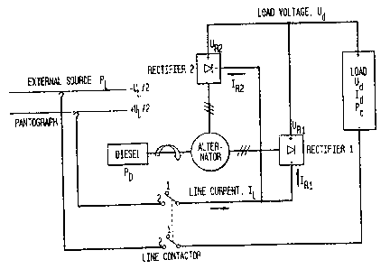
Connect Seguence; Making the External Series Connection Under Load
The commutation process to connect the external source in series and
switch the rectifier outputs from series to parallel configuration is a
process
comprising at least the following steps set forth in Figure 8. In the
preferred
embodiment, the controller controls the operation.
In summary, the connection sequence of the preferred embodiment
begins with the rectifiers of the dual-windings of a source in a series
configuration. The external source is placed in a parallel configuration with
one of the rectifiers and the internal source gradually decreases in voltage
until this rectifier is reverse biased, i.e., no longer supplying power to the
load.
s
CA 02355670 2001-06-15
WO 00/37279 PCT/US99/30426
The reversed biased rectifier is then placed in parallel with the other
rectifier in
order to provide twice the current as the original configuration.
Step 802 begins from an initial state of Diesel Operation with the
rectifier outputs connected in series and the load supplied by the diesel
engine (Step 804). During Diesel Operation, the alternator excitation and
engine speed are controlled by the controller (CPU, Figure 4) so as to meet
the power, voltage, and current requirements of the toad. For diesel boost
operation, the system controller (also referred to as the TCU (Traction
Control
Unit)) controls the switching in Figure 4-6 on the basis of input signals such
as
the external line voltage and vehicle speed. The TCU controls an automated
sequence to connect and disconnect the external power source while under
full load.
The transition begins by measuring the external line voltage (Step 806)
and adjusting the alternator excitation (Step 808) so that the rectified
outputs
of each winding are close to the external line voltage (U~). The line
contactor
is then closed (Step 810) to connect the external source in parallel with the
output of Rectifier 1. No precharging is required before making the
connection because the system controller maintains the rectifier output
voltage to be close to (U~) the external line voltage and no appreciable
current
flows through the line contactor.
Next, the excitation is reduced slightly (Step 812) to lower the DC
output of the rectifiers and therefore lower the input voltage of the
inverter's
DC link. As a result, the external supply reverse biases Rectifier 1 and
causes
the portion of the load carried by Rectifier 1 to be transferred to the
external
supply. The load current is now supplied by the external source in series with
Rectifier 2. No current flows in Rectifier 1. Opening switch S2 (Step 814) now
opens the series connection between the two rectifiers at zero current. Due to
this arrangement, the load is maintained at all times at the voltage and
current
level corresponding to its rated power during Diesel Operation (Po).
9
CA 02355670 2001-06-15
WO 00/37279 PCT/US99/30426
It will be appreciated that this circuit topology is able to advantageously
connect the line without any precharge process and then open switch S2 at
zero current because the load is a voltage source inverter. The controller for
such an inverter is able to compensate, within certain limits, for variations
in
the input voltage connected to the inverter's DC link and maintain the load at
full power. Therefore, in addition to its normal function of controlling the
load
inverter, the controller also actively adjusts the excitation to vary (Step
816)
the inverter input voltage during the connection sequence to provide a smooth
transition to series operation while under load. This results in a seamless
series connection to the external source.
At this time, the series connection between Rectifier 1 and Rectifier 2 is
open and has no effect on the operation because there is no current flowing in
Rectifier 1. The negative output of Rectifier 1 is then disconnected (Step
818)
from the negative terminals of the DC bus and reconnected to the negative
output of Rectifier 2. Here again, no current flows in Rectifier 1 or either
switch due to the circuit topology.
Step 822 is to connect Rectifier 1 in parallel with Rectifier 2 by
connecting positive output of Rectifier 1 to the positive output of Rectifier
2.
Since the alternator windings share a common flux path, half of the load
current flowing in winding 1 quickly and smoothly transfers to winding 2 until
both windings and rectifiers equally share the toad, thereby completing the
transfer.
The outputs of the two rectifiers are now connected in parallel with
each other and in series with the external source. Each alternator winding
operates at its full rated voltage but only half its rated current. The diesel
operates at half its rated output (0.5*P~) and the external supply provides
the
rest of the power (0.5*P~). The load operates at its rated voltage and with
current and power equivalent to what the diesel engine alone provides during
Diesel Operation.
CA 02355670 2001-06-15
WO 00/37279 PCT/US99/30426
The next Step (824) is to increase the load power to its maximum by
increasing the load current. The current splits equally between the two
rectifiers and alternator windings so they are not overloaded. The increased
power comes partially from the diesel and partially from the external source.
The transition from full diesel power (Pp) to full load power (PF=Pp+P~)
occurs
at the same voltage by doubling the current drawn from the line and through
the alternator. This power increase is also a seamless transition in that load
voltage remains constant and the controller simply adjusts the load to draw
more current from the combined power sources.
After the rectifiers are connected in parallel, the controller adjusts the
alternator excitation so as to maintain the load at the most optimum voltage.
This voltage could be adjusted, for example, in consideration of the vehicle's
speed to maintain the load at its most desirable operating point. The
controller can also compensate for variations in line voltage by adjusting the
excitation and so maintain the load at its ideal operating point.
Disconnect Seauence: Removing the External Series Connection Under
Load
The commutation process to disconnect the external power source and
restore the series connection of the two rectifier outputs for Diesel
Operation
will be described with reference to Figure 9.
In Step 902 the controller seamlessly reduces the load current to a
level that can be supplied by the diesel engine (Po). Step 904 is to
disconnect
the positive output of Rectifier 1 from the positive output of Rectifier 2.
This
removes the parallel rectifier connection and the load current smoothly
transfers completely to the remaining winding. The engine, alternator and
rectifier still provide half the load power, but one half of the alternator
and one
rectifier are at full current and voltage and the other half have no current.
The
other half of the load voltage is supplied in this instance by the line. Step
906
is to disconnect the negative output of Rectifier 1 from the negative output
of
Rectifier 2 and reconnect the negative output of Rectifier 1 to the negative
terminal of the DC bus (Step 908).
a
CA 02355670 2001-06-15
WO 00/37279 PCT/US99/30426
In preparation (Step 910) for restoring the serial connection between
the two rectifier outputs, the controller adjusts the excitation to ensure
that the
rectifier output is slightly less than the line voltage. The positive output
of
Rectifier 1 is then reconnected in Step 912 to the negative output of
Rectifier
2. No current flows during or after this transition because the line voltage
reverse biases Rectifier 1. The controller in Step 917 then raises the
excitation until Rectifier 1 begins to conduct and the diesel picks up the
second half of the load, reducing the line current to zero, seamlessly
transferring the load to the diesel. The line contactor is now opened at zero
current (Step 916). This leaves the system back in Diesel Operation with
(diesel) rated current and voltage at the load.
In the preferred embodiment, the two switches used to reconfigure the
system for Diesel Boost Trolley Operation are single pole {not three phase)
and are not required to make or break large currents or voltages. They
generally operate at zero current.
The precharge circuit in the embodiment shown in Figure 5 controls the
rate of power transfer from the alternator and Rectifier 1 to the external
source. This simplifies the control problem and allows the system controller
to
maintain the rated load voltage during the transfer. The rating of the
precharge circuit may be minimized because it only needs to accommodate
the difference in voltage between the external source voltage and the output
of Rectifier 1 at the beginning of the transfer. In some embodiments of the
invention (Figure 6), the precharge circuit can be eliminated by means of a
proper control strategy implemented by the controller.
The circuit of the present invention advantageously allows a high-
current, high-voltage load to be supplied with supplemental power from an
existing high-current, low-voltage source. Further, the circuit allows the
load
to operate at power levels beyond what available diesel engines can provide.
In addition, the circuit topology minimizes the size of the alternator by
permitting parallel connection of the windings (through the rectifiers) to
12
CA 02355670 2001-06-15
WO OOI37279 PCT/US99/30426
effectively double its rated current when only half its rated voltage is
required.
The present invention provides a smooth and bumpless transfer, allowing the
load to operate at maximum diesel power throughout the transition seamlessly
and without appreciably dropping the flow of power to the load or raising the
voltage of the load while operating within the rating constraints of the first
and
second sources Po, P~ such that the power transfer is transparent to the load,
i.e., no anamolies in power (current or voltage interruptions, spikes,
oscillations, drop-off, perturbations, etc.) are sensed by the load.
13
CA 02355670 2001-06-15
WO 00/37279 PCT/US99/30426
The present invention shall now be described as a particular example.
However, it shall be clear that the invention is not limited to such example
and
may, in addition, be practiced otherwise. The following notations will be used
in the following example.
Notation: Subscripts:
U = Voltage ~ = Line (L=Trolley Line)
I = Current o = Diesel
P = Power d = Load Value (d=DC)
R = Rectifier
A diesel powered off-highway haul truck (Figure 10) is driven by two
AC electric traction motors supplied by two inverters in accordance with the
circuit topology shown in Figure 4. The inverters are capable of handling a
combined power Pd at DC input voltage Ud and DC input current Id. The
inverters are connected to a common DC bus and are fed by an alternator
and rectifier bridge at the rated inverter input voltage Ud. At this voltage
level
the alternator and rectifier can supply current Ip, where Ip is only
approximately half of Id. The alternator is driven by a diesel engine capable
of
delivering maximum power Pp, where Po is approximately half of the load
power Pd.
While travelling up a grade, it is desired to ascent the grade at a faster
rate. To that end, the vehicle is connected to a low voltage trolley line with
voltage U~ by means of a pantograph, thereby increasing the DC current
supplied to the inverters from I~ to I~. This must be done under the
environment of maintaining the inverters at their rated DC input voltage Ud.
This provides approximately twice the power to the load and thereby doubles
the vehicle speed while on grade when connected to the low voltage trolley
line.
14
CA 02355670 2001-06-15
WO 00/37279 PCT/US99/30426
The Parallel Line Connection of the trolley line with the DC bus is not
possible since the voltage required by the inverters Ud is almost twice the
available trolley voltage U~. A Series Line Connection to the trolley line is
not
possible since the available trolley current I~ is twice the rated DC current
of
the alternator and rectifier Ip and they will rapidly overheat.
The truck is able to drive from the loading shovel to the trolley line
under diesel power Pp and can go up the grade at this power level. To utilize
the additional power available from the trolley, the truck must be able to
connect to the trolley line while maintaining continuous operation on the
grade
at power Po. If the power level falls during the transition, the truck will
slow
below the minimum allowable trolley speed limit (a safety limitation for mine
personnel) and be forced stop.
Prior to this invention, it has not been possible for the high voltage
inverters to make use of the available low voltage trolley power. Using the
circuit topology and control strategy described in the present invention it is
now possible to operate the truck on a low voltage trolley in Diesel Boost
Mode at the full rated load power Pd.
Diesel Boost Configuration and Control Strategy of the Present invention
The single winding alternator and diode rectifier of Figure 1 are
replaced with a dual winding alternator connected to two diode rectifiers
(Figure 6). The two windings are identical and each supplies half the rated
voltage of the alternator. A two-pole line contactor brings the trolley
voltage to
where it can be connected in parallel with Rectifier 1. A single pole, double-
throw changeover switch (S3) and two single-pole, single-throw switches (S~
and S2) enable the outputs of Rectifier 1 to be connected either in series or
parallel with Rectifier 2. An additional single pole high-speed circuit
breaker
provides overcurrent protection between the truck and trolley systems.
With all the switches in position 1, the two rectifiers are in series and
there is no connection to the trolley line. The load operates at Uo=Ud,maX,
ID~Id,max and Po<PdmaX. With all the switches in position 2, the two
rectifiers
is
CA 02355670 2001-06-15
WO 00/37279 PCT/US99/30426
are in parallel with each other and in series with the trolley line. The load
operates at U~=Ud,max, IL=Id,meX and Pp+ P~=Pdmax.
The truck operates in normal Diesel mode when the switches are in
position 1 and all the power is provided by the diesel engine. Transition from
Diesel to Diesel Boost operation functions according to the connection
sequence described previously. During Diesel Boost operation, the switches
are all in position 2. Transition from Diesel Boost to Diesel operation
functions according to the disconnect sequence described previously.
Of particular importance is that the duration of the actual transfer from
one mode to the other is not critical because the transfer takes place with
the
vehicle operating under full diesel power. With no precharge interval, the
limiting factor in the transition is the time required to raise and lower the
pantograph. Approximately one second is required for the DC link voltage
regulation to stabilize before the line contactor is closed and then the
connect
sequence begins. It has been found that, with the present invention, within
one second after S~ is closed the controller can raise the load power to its
full
level.
The transition from diesel to trolley is bumpless and the vehicle will not
slow down at all during the transfer. While on trolley, the diesel power (Po)
is
supplemented by power from the wayside substations (P~) and the inverters
are able to operate at their full power. Depending on the exact voltage,
current and power levels involved, this approximately doubles the vehicle's
on-grade speed. The transition from trolley to diesel is also quick and smooth
with the present invention. Hence, the present invention resolves the
previous problems seamlessly and without appreciably dropping the flow of
power to the load or raising the voltage of the load while operating within
the
rating constraints of the first and second sources Po, P~ such that the power
transfer is transparent to the load, i.e., no anamolies in power (current or
voltage interruptions, spikes, oscillations, drop-off, perturbations, etc.)
are
sensed by the load.
16
CA 02355670 2001-06-15
WO 00/37279 PCT/US99/30426
Alternative Examples of the Invention
In mines where the trolley voltage is suitably high (U~=tJd) the truck can
operate in Direct Trolley (DT) mode. This uses the Parallel Line Connection
described with reference to Figure 2 and does not require switches S~, S2 or
S3, only the circuit breaker and line contactor.
There are, however, some situations where both high and low voltage
trolley systems are installed, or could be installed, in the same mine. In
this
case, it would be desirable to operate the truck on either line using either
the
low voltage line in Diesel Boost Trolley (DBT) mode or the high voltage line
in
Direct Trolley (DT) mode. A variation of the invention, as shown in Figure 7,
is the addition of a second single-pole, double-throw switch (S4) to allow the
truck to operate on both high and low voltage trolley systems.
The switch's common terminal in this case is connected to the load
side of the positive pole of the line contactor. The other terminals are
connected to the positive and negative sides of Rectifier 2, such that in
position 1, the line contactor is connected to the negative terminal of
Rectifier
2 and in position 2 the line contactor is connected to the positive terminal
of
Rectifier 2. With S4 in position 1, the truck can operate in either Diesel or
Diesel Boost mode by moving the other switches to position 1 or position 2, as
previously described. This is suitable for operation under diesel power or on
the low voltage trolley system, when U~<Ud. With S4 in position 2, and all
other switches in position 1, the truck can operate in Direct Trolley mode as
described above. This is suitable for operation on the high voltage trolley
system, where U~=Ud. In operation, the operator drives the vehicle under
either trolley system and then raises the pantograph. The system controller
then measures the trolley line voltage and positions S4 accordingly. This
provides safe, automatic, and reliable operation on either trolley system
without any consideration from the driver as to the operating voltage of the
trolley line.
17