Note: Descriptions are shown in the official language in which they were submitted.
CA 02355819 2001-08-27
FPO1-0117-00
TITLE OF THE INVENTION
Optical Fiber, Method of Making Optical Fiber Preform,
and Method of Making Optical Fiber
BACKGROUND OF THE INVENTION
Field of the Invention
The present invention relates to an optical fiber for
transmitting light; a method of making an optical fiber
preform, and a method of making an optical fiber.
Related Background Art
In light transmissions using an optical fiber,
transmission loss such as Rayleigh scattering loss caused
by Rayleigh scattering within the optical fiber, structural
asymmetry loss caused by disturbance in structures within
the optical fiber, and the like becomes problematic.
These kinds of transmission loss are greatly influenced
by the tension applied to the optical fiber when making the
optical fiber by drawing an optical fiber preformupon heating.
Namely, if the tension applied to the optical fiber is too
low or too high with respect to the tension range considered
favorable at the time of drawing, then the Rayleigh scattering
loss, structural asymmetry loss, and the like within the
optical fiber may increase. More specifically, the
structural asymmetry loss increases at a lower tension. At
a higher tension, on the other hand, both the Rayleigh
1
CA 02355819 2001-08-27
FPO1-0117-00
scattering loss and structural asymmetry loss increase.
Such a tension at the time of drawing also influences
transmission characteristicsof the opticalfiber other than
its transmission loss, its structures, its mechanical
strength, and the like.
The tension applied to the optical fiber at the time
of drawing usually changes with time during when the optical
fiber preform is being drawn upon heating. Consequently,
if the optical fiber pre form is drawn as it is, the tension
applied to the optical fiber preform may vary greatly over
the whole length thereof, thereby making it difficult to
make a long optical fiber yielding a low transmission loss .
Therefore, tension control for keeping the tension within
a favorable tension range is necessary in the optical fiber
drawing step.
SUN~1ARY OF THE INVENTION
The above-mentioned favorable tension range at the time
of drawing an optical fiber may vary depending on the structure
and material of an optical fiberpreform, its specificdrawing
condition, and the like. Here, if the tension range
permissible as a drawing condition for yielding a favorable
optical fiber is narrow, then it becomes very hard to carry
out tension control at a sufficient accuracy over the whole
length of the optical fiber preform.
For example, in an optical fiber (optical fiberpreform)
2
CA 02355819 2001-08-27
FPO1-0117-00
having a core made of pure Si02 (pure silica) , its core region
yields a viscosity higher than that in its cladding region
doped with F or the like ( see, for example, "Hanawa et al . ,
the Transactionsof theInstitute of Electronics,Information
and Communication Engineers, 1989/3, Vol. J72-C-I, No. 3,
pp. 167-176" ) . Therefore, at the time of drawing the optical
fiber preform, the stress occurring within the optical fiber
is concentrated into the core, thus causing transmission
losstoincrease. For restraining the transmissionlossfrom
increasing due to the stress concentration into the core
in such a case, severe tension control is necessary at a
high accuracy, or it may become problematic in that tension
control cannot be carried out in such a manner as to
sufficiently lower the transmission loss, and so forth.
Also, "Sakaguchi, the Transactions of the Institute
of Electronics, Information and Communication Engineers,
2000/1, Vol. J83-C, No. 1, pp. 30-36", discloses that
annealing an optical fiber after drawing reduces the Rayleigh
scattering within the optical fiber. Namely, the Rayleigh
scattering intensity within glass is not constantly fixed
by materials thereof, but depends on a fictive temperature
Tf which is a virtual temperature indicative of the randomness
in the state of arrangement of atoms within glass.
Specifically, the Rayleigh scattering intensity increases
as the fictive temperature Tf within glass is higher
(randomness is greater).
3
CA 02355819 2001-08-27
FP01-0117-00
Y
In this regard, when drawing an optical fiber preform
upon heating, a heating furnace is installed downstream a
drawing furnace and is heated such that the drawn optical
fiber attains a temperature within a predetermined
temperature range when passing through the heating furnace.
As a consequence, the heating by use of the heating furnace
prevents the drawn optical fiber from cooling drastically,
whereby the optical fiber is annealed. Here, due to the
structural relaxation of glass caused by rearrangement of
atoms, the fictive temperature Tf within the optical fiber
decreases, whereby the Rayleigh scattering intensity within
the optical fiber is suppressed.
However, the inventor has found that, even when such
a manufacturing method yielding an effect of lowering the
Rayleigh scattering loss is used, if the tension at the time
of drawing the optical fiber preform is not within the
favorable tension range, the structural asymmetry loss will
increase due to the stress concentration into the core, and
so forth, whereby the transmission loss may not be reduced
as a whole.
In order to overcome the foregoing problems, it is an
object of the present invention to provide an optical fiber,
a method of making an optical fiber preform; and a method
of making an optical fiber which facilitate the tension
control at the time of drawing.
For achieving such a problem, the optical fiber in
4
CA 02355819 2001-08-27
FPO1-0117-00
accordance with the present invention comprises a core
region; and a cladding region, provided at an outer periphery
of the core region, having one or a plurality of cladding
layers doped with fluorine which lowers a refractive index,
wherein the outermost cladding layer of the one or plurality
of cladding layers is configured such that fluorine
successively lowers the doping amount thereof in an outer
peripheral part including an outer periphery thereof to a
predetermined doping amount which is the minimum doping
amount of fluorine within the layer.
In the above-mentioned optical fiber, among the
cladding layers formed as being doped with F (fluorine),
the outermost cladding layer is configured so as to yield
such an F doping amount distribution that the doping amount
of F gradually decreases from the inner side to the outer
side within the outer peripheral part (the outer periphery
and its vicinity) in the outermost cladding layer. Here,
viscosity becomes higher in the outer peripheral part of
the outermost cladding layer in which the doping amount of
F is smaller, whereby the stress applied to the inside of
the optical fiber is dispersed into the outer peripheral
part of the outermost cladding layer, which suppresses the
stress concentration into the core. Also, this stress
dispersion makes it possible to widen the favorable tension
range permissible at the time of drawing the optical fiber.
As a consequence, the optical fiber in accordance with
5
CA 02355819 2001-08-27
FPO1-0117-00
,,
the present invention becomes an optical fiber having a
configuration which simplifies the tension control at the
time of drawing. At the same time, the increase in
transmission loss and the deterioration in transmission
characteristics are prevented from occurring due to the
excessive stress concentration into the core and the like,
which realizes an optical fiber having stable transmission
characteristics over the whole length thereof.
Since the region reducing the doping amount of F is
the outer peripheral part of the outermost cladding layer,
the F doping amount distribution has no influence over the
light transmitted through the core region and the cladding
region in the vicinity thereof. Therefore, while favorably
keeping transmission characteristics and the like of the
optical fiber, it can facilitate the tension control, or
reduce the transmission loss thereby.
The method of making an optical fiber preform in
accordance with the present invention comprises: (1) a
synthesizing step of depositing a glass fine particle onto
an outer periphery of a core preform including at least a
core region, so as to synthesize a glass fine particle layer
to become the outermost cladding layer in one or a plurality
of layers of cladding in a cladding region disposed at an
outer periphery of the core region; (2) a dehydrating step
of dehydrating the synthesized glass fine particle layer
upon heating; and (3) a consolidating step of consolidating
6
CA 02355819 2001-08-27
FPO1-0117-00
the dehydrated glass fine particle layer upon heating so
as to form the outermost cladding layer, thus forming an
optical fiber preform having the core region and the cladding
region having the one or plurality of layers of cladding;
wherein (4), before consolidating the glass fine particle
layer upon heating, doping the glass fine particle layer
with fluorine and eliminating a part of doped fluorine from
an outer peripheral part including an outer periphery
thereof.
Drawing the optical fiber preform obtained by such a
method of making an optical fiber pre form makes it possible
to yield an optical fiber which is doped with or rid of F
such that the doping amount of F within the outer peripheral
part in the outermost cladding layer in the cladding layers
of the cladding region successively decreases to a
predetermined doping amount which is the minimum doping
amount of F within the layer.
Alternatively, the method of making an optical fiber
preform in accordance with the present invention comprises:
(1) a synthesizing step of depositing a glass fine particle
onto an outer periphery of a core preform including at least
a core region, so as to synthesize a glass fine particle
layer to become the outermost cladding layer in one or a
plurality of layers of cladding in a cladding region disposed
at an outer periphery of the core region; (2) a dehydrating
step of dehydrating the synthesized glass fine particle layer
7
CA 02355819 2001-08-27
FPOl-0117-00
upon heating; and (3) a consolidating step of consolidating
the dehydrated glass fine particle layer upon heating so
as to form the outermost cladding layer, thus forming an
optical fiber preform having the core region and the cladding
region having the one or plurality of layers of cladding;
wherein (4) the glass fine particle layer is synthesized
in the synthesizing step such that the glass fine particle
layer is dopedwith fluorine by using amaterial gas containing
fluorine while the material gas containing fluorine is
adjusted such that the doping amount of fluorine successively
decreases within an outer peripheral part including an outer
periphery thereof.
Drawing the optical fiber preform obtained by such a
method of making an optical fiber preform similarly makes
it possible to yield an optical fiber which is doped with
F such that the doping amount of F within the outer peripheral
part in the outermost cladding layer successively decreases
to a predetermined doping amount which is the minimum doping
amount of F within the layer.
The method of making an optical fiber in accordance
with the present invention comprises preparing an optical
fiber pre form comprising a core region, and a cladding region,
provided at an outer periphery of the core region, having
one or a plurality of cladding layers doped with fluorine
which lowers a refractive index, in which the outermost
cladding layer of the one or plurality of cladding layers
8
CA 02355819 2001-08-27
FPO1-0117-00
is configured such that fluorine successively lowers the
doping amount thereof in an outer peripheral part including
an outer periphery thereof to a predetermined doping amount
which is the minimum doping amount of fluorine within the
'layer; and, when drawing the optical fiber preform upon
heating, drawing the optical fiber pre form at a tens ionwithin
the range of 0.05 to 0.20 N.
Since the optical fiber preform (optical fiber) has
such a configuration that the stress is dispersed into the
outer peripheral part of the outer cladding layer, whereas
the tension control is carried out such that the tension
at the time of drawing is held within the favorable tension
range of 0.05 to 0.20 N, an optical fiber having favorable
transmission characteristics over the whole length thereof
can be obtained.
Alternatively, the method of making an optical fiber
in accordance with the presentinvention comprisespreparing
an optical fiber preform comprising a core region; and a
cladding region, provided at an outer periphery of the core
region, having one or a plurality of cladding layers doped
with fluorine which lowers a refractive index, in which the
outermost cladding layer of the one or plurality of cladding
layers is configured such that fluorine successively lowers
the doping amount thereof in an outer peripheral part
including an outer periphery thereof to a predetermined
doping amount which is the minimum doping amount of fluorine
9
CA 02355819 2001-08-27
FPO1-0117-00
within the layer; and, when drawing the optical fiber preform
upon heating, causing a heating furnace disposed downstream
a drawing furnace to heat the optical fiber drawn by the
drawing furnace to a temperature within a predetermined
temperature range.
Thus, while the structure mentioned above suppresses
the stress concentration and reduces the transmission loss,
annealing the optical fiber by using the heating furnace
disposed downstream the drawing furnace upon heating lowers
the fictive temperature Tf within the optical fiber, which
makes it possible to reduce the Rayleigh scattering loss.
When a resin coating section for coating the drawn
optical fiber with a resin exists in the above-mentioned
methods of making an optical fiber, it is preferred that
the heating furnace disposed downstream the drawing furnace
be located between the drawing furnace and the resin coating
section.
The present invention will become more fullyunderstood
from the detailed description given hereinbelow and the
accompanying drawings which are given by way of illustration
only, and thus are not to be considered as limiting the present
invention.
Further scope of applicability of the present invention
will become apparent from the detailed description given
hereinafter. However, it should be understood that the
detailed description andspecific examples, whileindicating
CA 02355819 2001-08-27
FP01-0117-00
preferred embodiments of the invention, are given by way
ofillustration only,since variouschangesand modifications
within the spirit and scope of the invention will become
apparent to those skilled in the art from this detailed
description.
BRIEF DESCRIPTION OF THE DRAWINGS
Fig. 1 is a view schematically showing the
cross-sectional structure and refractive index profile of
a first embodiment of the optical fiber;
Fig. 2 is a view schematically showing the
cross-sectional structure and refractive index profile of
a second embodiment of the optical fiber;
Fig. 3 is a flowchart schematically showing the method
of making an optical fiber;
Fig. 4 is a view schematically showing the method of
making an optical fiber, and an embodiment of the drawing
apparatus used for making the optical fiber;
Fig. 5 is a chart showing the refractive index profile
in a first comparative example of the optical fiber;
Fig. 6 is a chart showing the refractive index profile
in a second comparative example of the optical fiber;
Fig. 7 is a graph showing the dependence of transmission
loss upon tension in optical fibers;
Fig. 8 is a graph showing the dependence of transmission
loss upon tension in optical fibers; and
11
CA 02355819 2001-08-27
w FPOl-0117-00
Fig. 9 is a graph showing the dependence of transmission
loss upon bending diameter in optical fibers.
DESCRIPTION OF THE PREFERRED EMBODIMENTS
In the following, preferred embodiments of the optical
fiber, method of making an optical fiber preform, and method
of making an optical fiber in accordance with the present
invention will be explained in detail with reference to the
drawings. In the explanation of the drawings, constituents
identical to each other will be referred to with numerals
or letters identical to each other without repeating their
overlapping descriptions. Also, ratios of sizes in the
drawings do not always correspond to those explained.
In the following, the relative refractive index
difference indicating the value of refractive index in each
part is assumed to be defined by the refractive index
difference from pure Si02 (pure silica) expressed in terms
of ~ while the refractive index in pure Si02 is taken as a
reference (relative refractive index difference = 0) . The
average doping amount of F or average relative refractive
index difference in each region or each layer is defined
by the value averaging the F doping amounts or relative
refractive index differences weighted according to their
corresponding areas within the region (within the layer).
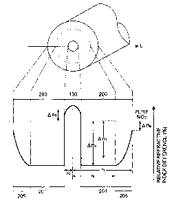
First, the configuration of the optical fiber will be
explained. Fig. 1 is a view schematically showing the
12
CA 02355819 2001-08-27
FPO1-0117-00
cross-sectional structure of a first embodiment of the
optical fiber in accordance with the present invention, and
its refractive index profile in the fiber diameter direction
(direction indicated by the line L in the drawing) . Though
different in scale, the abscissa of the refractive index
profile (relative refractiveindex difference distribution)
shown in Fig. 1 corresponds to individual positions in a
cross section, perpendicular to the center axis of the optical
fiber, extending along the line L shown in the cross-sectional
structure in the drawing.
This optical fiber is an optical fiber of Si02 glass
( silica glass ) type; and comprises a core region 100 including
the center axis of the optical fiber, and a cladding region
200 provided at the outer periphery of the core region 100.
In such a configuration, the light transmitted through the
optical fiber is transmitted through the core region 100
and the part of cladding region 200 on the inner periphery
side thereof near the core region 100.
The core region 100 is formed such that its outer
periphery has a radius of ro. In the core region 100, pure
Si02 glass is doped with a predetermined amount of C1
(chlorine) as an additive for raising the refractive index.
As a consequence, the average relative refractive index
difference within the core region 100 is ~n0 (where ono >
0) . In this embodiment, as shown in Fig. 1, the core region
100 is formed so as to have a graded refractive index
13
CA 02355819 2001-08-27
FPO1-0117-00
distribution in which the doping amount of C1 and relative
refractive index difference are maximized near the center
axis of the optical fiber.
On the other hand, in this embodiment, the cladding
region 200 is configured so as to have a single cladding
layer 201. The cladding layer 201 is formed such that its
outer periphery has a radius of rl. In the cladding layer
201, pure Si02 glass is doped with a predetermined amount
of F (fluorine) as an additive for lowering the refractive
index. As a consequence, the average relative refractive
index difference within the cladding layer 201 is Onl (where
~nl < 0 ) .
In the configuration of this embodiment, the cladding
layer 201 is the outermost cladding layer within the cladding
region 200. In its region including the outer periphery (the
part located at the radius of rl) , a regional area whose radius
ranges from ra to rl (where ro < ra < rl) is defined as an
outer peripheral part 205, which is configured such that
the F doping amount and relative refractive index difference
attain a predetermined distribution therewithin.
Namely, in the cladding layer 201, which is the
outermost cladding layer, the regional area whose radius
ranges from ro to ra on the inside of the outer peripheral
part 205 is doped with a substantially constant amount of
F which is the maximum doping amount of F within the cladding
layer. As a consequence, the part on the inside of the outer
14
CA 02355819 2001-08-27
FPO1-0117-00
peripheral part 205 attains a relative refractive index
difference of ~nb which is the minimum relative refractive
index difference of F (corresponding to the maximum F doping
amount and having the maximum absolute value) within the
layer.
On the other hand, the outer peripheral part 205 is
doped with F such that the F doping amount successively
decreases from the inner side to the outer side from the
above-mentioned maximum doping amount of F to a predetermined
doping amount which is the minimum F doping amount within
the layer. As a consequence, the outer peripheral part 205
is configured such that its relative refractive index
difference changes from the inner side to the outer side
from the above-mentioned minimal relative refractive index
difference of ~nb to Ona, which is the maximum relative
refractive index difference (corresponding to the minimum
F doping amount and having the minimum absolute value) within
the layer.
In the optical fiber of this embodiment, as mentioned
above, the F doping amount distribution within the cladding
layer 201 acting as the outermost cladding layer of the
cladding region 200 is configured such that the F doping
amount in its outer peripheral part 205 gradually decreases
as shown in Fig. 1.
The core region 100 of this optical fiber is made of
C1-doped Si02 core . Though slightly lowered by the C1 doping,
CA 02355819 2001-08-27
FPO1-0117-00
the viscosity of the core region 100 is higher than that
of the cladding region 200 due to the doping amount and the
like. Therefore, if the cladding layer 201 has a normal
configuration which is doped with a substantially constant
doping amount of F, the stress is concentrated into the core
in excess.
When the F doping amount is lowered in the outer
peripheral part 205 of the cladding layer 201 as mentioned
above, by contrast, the viscosity of the outer peripheral
part 205 becomes higher, so that the stress is dispersed
into the outer peripheral part 205, whereby the stress
concentration into the core is suppressed.
Since the stress concentration into the core is
suppressed as such, the favorable tension range permitted
at the time of drawing the optical fiber becomes wider, thereby
facilitating the tension control at the time of drawing.
Also, the stress is prevented from being concentrated into
the core in excess, and the increase in transmission loss
and the deterioration in transmission characteristics due
to insufficient tension control and the like are kept from
occurring, whereby an optical fiber having stable
transmission characteristics over the whole length thereof
is realized.
Preferably, concerning the minimum relative
refractive index difference ~nb in the part on the inside
of the outer peripheral part 205 and the maximum relative
16
CA 02355819 2001-08-27
FPO1-0117-00
refractive index difference Ana in the vicinity of the outer
periphery of the outer peripheral part 205, the relative
refractive index difference ona is higher than ~nb by at least
0. 05$ ( Ona Z ~ttb +0.05% ) . More preferably, the former is
higher than the latter by at least 0 . 1~ ( Ona Z Onb +0.1% ) .
When the amount of decrease in F doping amount in the
outer peripheral part 205 of the cladding layer 201 is at
least 0.05 or at least 0.1$, in terms of the relative
refractive index difference, the viscosity in the vicinity
of the outer periphery of the outer peripheral part 205 can
be made on a par with that of the core region 100, for example,
whereby the effect of dispersing the stress into the outer
peripheral part 205 can fully be improved.
Concerning the doping of the core region 100 with C1,
it is preferred that the average relative refractive index
difference fall within the range of 0.01% s ~rco s 0.12% in order
to fully secure the effect of confining light into the core
region 100, and the like. Since this C1 doping is less
influential in transmission loss and the like, the C1-doped
core can be handled similarly to the pure Si02 core. The
C1 doping is also effective in lowering the viscosity of
the core region 100. The core region 100 may have a graded
refractive index distribution as shown in Fig. 1, or a
substantially constant refractive index distribution
therewithin.
For suppressing the stress concentration into the core
17
CA 02355819 2001-08-27
FPO1-0117-00
or reducing the transmission loss due to the facilitation
of the tension control at the time of manufacture (at the
time of drawing), it is specifically preferred that the
Rayleigh scattering coefficient A be 0.81 dB/km~um9 or less,
or the transmission loss al.oo at a wavelength of 1.00 um be
0.82 dB/km or less.
In an optical fiber with a pure Si02 core (or a C1-doped
Si02 core similar to the pure Si02 core) having a normal
configuration, the Rayleigh scattering coefficient A and
the transmission loss al.oo are about 0.85 dB/km~pm' and 0.86
dB/km (reference values), respectively. By contrast, the
optical fiber in accordance with this embodiment can make
the Rayleigh scattering coefficient A and the transmission
loss al, oo fall within their respective ranges mentioned above,
which are reduced by about 5~ from their respective reference
values.
Such a reduction in the Rayleigh scattering coefficient
A or the transmission loss al.oo is realized by the
above-mentioned configuration of the optical fiber, or a
combination of thisconfiguration and a manufacturing method
which can reduce the transmission loss caused by Rayleigh
scattering loss and the like. The reduction in transmission
loss effected by the manufacturing method will be explained
later.
The Rayleigh scattering coefficientAwill be explained
here. The Rayleigh scattering coefficient A is an amount
18
CA 02355819 2001-08-27
FPO1-0117-00
which acts as an index of the Rayleigh scattering loss included
in the transmission loss of the optical fiber. In general,
the transmission loss a~, (dB/km) of the optical fiber at a
wavelength h is represented by the following expression:
ax = A~~.' + B + C(~,
according to the Rayleigh scattering loss and other
transmission loss components such as structural asymmetry
loss. In this expression, the first term, A/A4 (dB/km),
indicates the Rayleigh scattering loss, and its coefficient
A is the Rayleigh scattering coefficient (dB/kmy.m'). As
can be seen from the above expression, the Rayleigh scattering
loss is in proportion to the Rayleigh scattering coefficient
A, whereby the Rayleigh scattering coefficient A can be used
as an index of the reduction in Rayleigh scattering loss.
In view of the above-mentioned expression, the Rayleigh
scattering coefficient A can be determined from data
concerning the dependence of transmission loss (e.g., the
gradient in a 1/1~' plot) upon wavelength.
As for the transmission loss in the optical fiber of
the present invention, a numeric range is given to the
transmission loss al.oo at a wavelength of 1.00 dun in the
condition mentioned above. This is because of the fact that
the value of transmission loss at a wavelength of 1.00 um
is greater than that in the 1.55-dun band used for optical
transmission or the like and can be evaluatedwith a sufficient
accuracy in a relatively short optical fiber sample having
19
CA 02355819 2001-08-27
FPO1-0117-00
a length of about 1 to 10 km.
Also, the transmission loss al.oo at a wavelength of
1.00 ~zm and the transmission loss al.ss at a wavelength of
1.55 um correspond to each other with a predetermined
relationship therebetween. Therefore, if the transmission
loss al.oo is reduced, then the reduction can similarly be
seen concerning the transmission loss al.ss. Specifically,
from the above-mentioned expression, transmission losses
al . oo and al . ss become
al.~ ~A+B+C(1.00~, and
al.ss ~ A x 0.17325 + B + C (1.55 ~ ,
thereby yielding the relationship of
ai.oo ~ al.ss + A x 0.82675 + C(1.00~- C(1.55
therebetween.
Fig. 2 is a view schematically showing the
cross-sectional structure of a second embodiment of the
optical fiber in accordance with the present invention, and
its refractive index profile in the fiber diameter direction.
As in the first embodiment, this optical fiber is an
optical fiber of SiQ2 glass (silica glass) type; and comprises
a core region 100 including the center axis of the optical
fiber, and a cladding region 200 provided at the outer
periphery of~the core region 100. Here, the configuration
of the core region 100 is substantially the same as that
of the core region 100 in the optical fiber shown in Fig.
1.
CA 02355819 2001-08-27
FPO1-0117-00
On the other hand, the cladding region 200 in this
embodiment comprises two layers of cladding, i . a . , an inner
cladding layer 201 provided at the outer periphery of the
core region 100 and an outer cladding layer 202 further
provided at the outer periphery of the inner cladding layer
201.
The inner cladding layer 201 is formed such that its
outer periphery has a radius of rl. In the inner cladding
layer 201, pure Si02 glass is doped with a predetermined amount
of F (fluorine) as an additive for lowering the refractive
index. As a consequence, the average relative refractive
index difference within the inner cladding layer 201 is ~nl
(where ~nl < 0 ) .
The outer cladding layer 202 is formed such that its
outer periphery has a radius of r2. In the outer cladding
layer 202, pure Si02 glass is doped with a predetermined amount
of F (fluorine) . As a consequence, the average relative
refractive index difference within the outer cladding layer
202 is ant (where ~n2 < 0). However, the average F doping
amount in the outer cladding layer 202 is smaller than that
in the inner cladding layer 201, whereby the average relative
refractive index differences of cladding regions 201 and
202 have a relationship of 0 > ~n2 > ~nl.
Also, in the configurationof this embodiment, the outer
cladding layer 202 is the outermost cladding layer in the
cladding region 200. In its region including the outer
21
CA 02355819 2001-08-27
FPO1-0117-00
periphery, a regional area whose radius ranges from ra to
r2 (where rl < ra < r2) is defined as an outer peripheral part
205, which is configured such that the F doping amount and
relative refractive index difference attain a predetermined
distribution therewithin.
Namely, in the outer cladding layer 202, which is the
outermost cladding layer, the regional area whose radius
ranges from rl to ra on the inside of the outer peripheral
part 205 is doped with a substantially constant amount of
F which is the maximum doping amount of F. As a consequence,
the part on the inside of the outer peripheral part 205 attains
a relative refractive index difference of ~nb which is the
minimum relative refractive index difference within the
layer.
On the other hand, the outer peripheral part 205 is
doped with F such that the F doping amount successively
decreases from the inner side to the outer side from the
above-mentioned maximum doping amount of F to a predetermined
doping amount which is the minimum F doping amount within
the layer. As a consequence, the outer peripheral part 205
is configured such that its relative refractive index
difference changes from the inner side to the outer side
from the above-mentioned minimal relative refractive index
difference of ~nb to Ona, which is the maximum relative
refractive index difference.
In the optical fiber of this embodiment, as in the first
22
CA 02355819 2001-08-27
FPO1-0117-00
embodiment, the F doping amount distribution within the outer
cladding layer 202 acting as the outermost layer of the
cladding region 200 is configured such that the F doping
amount in its outer peripheral part 205 gradually decreases .
Therefore, the viscosity of the outer peripheral part 205
increases so much that the stress is dispersed into the outer
peripheral part 205, whereby the stress concentration into
the core is suppressed.
Since the stress concentration into the core is
suppressed as such, the favorable tension range permitted
at the time of drawing the optical fiber becomes wider, thereby
facilitating the tension control at the time of drawing.
Also, the stress is prevented from being concentrated into
the core in excess, and the increase in transmission loss
and the deterioration in transmission characteristics due
to insufficient tension control and the like are kept from
occurring, whereby an optical fiber having stable
transmission characteristics over the whole length thereof
is realized.
While the cladding region 200 in the optical fiber of
the first embodiment is constituted by a single cladding
layer 201, the cladding region 200 in the optical fiber of
the second embodiment comprises two layers, i . a . , the inner
cladding layer 201 having a greater F doping amount (smaller
relative refractiveindex difference) and the outer cladding
layer 202 having a smaller F doping amount (greater relative
23
CA 02355819 2001-08-27
FPOl-0117-00
refractive index difference).
In the cladding region 200 having such a two-layer
structure, the inner cladding layer 201 positioned at the
outer periphery of the core region 100 can efficiently confine
the transmitted light into the core region 100 and its vicinity.
On the other hand, the outer cladding layer 202 is effective
in adjusting transmission characteristics of the optical
fiber, reducing the stress concentration into the core, and
so forth. The configurations of the outer cladding layer
202 and the outer peripheral part 205 therewithin can reliably
suppress the stress concentration into the core region 100.
Preferably, for fully obtaining the effect of
suppressing the stress concentration into the core region
100, the average relative refractive index difference On2
of the outer cladding layer 202 is set so as to satisfy
Onz a-0.26% . More preferably, it is set so as to satisfy
~n2 z -0.22% .
Methods of making an optical fiber preform and an
optical fiber will now be explained. Fig. 3 is a flowchart
schematically showing a method of making an optical fiber
including a method of making an optical fiber preform, by
which the optical fiber preform and optical fiber having
the above-mentioned configuration are obtained.
In the manufacturing method shown in Fig. 3, an optical
fiber preform having a configuration in which the F doping
amountsuccessively decreases(therelative refractiveindex
24
CA 02355819 2001-08-27
FPO1-0117-00
difference successively increases) within the outer
peripheral part 205 of the outermost cladding layer to a
predetermined doping amount which is the minimum doping
amount of F within the outermost cladding layer, as
exemplified by the optical fibers in accordance with the
first and second embodiments, is prepared (step 5100
including steps 5101 to S106) . Then, thus obtained optical
fiber preform is drawn upon heating (5107) , so as to yield
an optical fiber configured as shown in Figs. 1 and 2 (S108) .
First, the preparation of the optical fiber preform
(5100) will be explained. Initially, a core preform
including at least a core region is prepared (5101) . As the
core pre form, a conventional core preform can be used. For
example, a preform formed with a core region or further with
a part of a cladding region and extended to a predetermined
length can be used. The core region can be a pure Si02 core
or a C1-doped Si02 core, for example.
When forming the core preform (extended core body) with
a part of the cladding region in a configuratiomhaving a
single cladding layer 201 as in Fig. 1, there is a method
forming a part thereof from the core pre form. In this case,
however, it is necessary that the core preform be free of
at least a regional area including the outer peripheral part
205. Zn a configuration having two cladding layers 201, 202
as in Fig. 2, there is a method forming the inner cladding
layer 201 from the core preform. The part of cladding region
CA 02355819 2001-08-27
FPO1-0117-00
formed in the core preform may be formed by synthesis,
dehydration, and consolidating as in the outermost cladding
layer, which will be explained later, or by a rod-in-collapse
method.
With respect to such a core preform, a synthesizing
method such as VAD method or OVD method is used so as to
synthesize a glass fine particle layer on its outer periphery
(5102; synthesizingstep). Specifically, fineparticles of
glass are generated by a flame from a glass synthesizing
burner to which a material gas having a predetermined gas
composition is supplied, and these fine particles of glass
are deposited on the outer periphery of the core preform,
so as to synthesize the glass fine particle layer. This glass
fine particle layer is a layer to become the outermost cladding
layer (or a predetermined part of on the outer side of the
outermost cladding layer including at least the outer
peripheral part thereof) after consolidating upon heating.
Subsequently, thus synthesized glass fine particle
layer is dehydrated upon heating (5103; dehydrating step) ,
and thus dehydrated glass fine particle layer is consolidated
upon heating (5105; consolidating step), so as to make an
optical fiber preform having the outermost cladding layer
formed from the glass fine particle layer (5106).
If necessary, the glass fine particle layer may be doped
with F by immersion (5104; immersing step) at a step between
the dehydrating step (S103) and the consolidating step (5105) .
26
CA 02355819 2001-08-27
FPO1-0117-00
In the immersing step, the atmosphere in the consolidating
furnace is set to a gas atmosphere containing a predetermined
concentration of F, and the glass fine particle layer is
doped with F by immersion in this gas atmosphere.
In such a method of making an optical fiber preform,
a method for yielding an F doping amount distribution
configured such that the doping amount gradually decreases
in the outer peripheral part of the glass fine particle layer
(outermost cladding layer) as shown in Figs. 1 and 2 is,
for example, one in which the glass fine particle layer is
doped with F before the glass fine particle layer is
consolidated upon heating and then, after the doping, a part
of thus added F is eliminated from the outer peripheral part
of the glass fine particle layer (corresponding to the outer
peripheral part of the outermost cladding layer) including
the outer periphery thereof.
Specifically, for example, a glass fine particle layer
made of Si02 is synthesized as a jacket layer (sooting;
synthesizing step) on the outer periphery of the core preform.
Thereafter, it is dehydrated by heating at 1200°C in an SiCl4
atmosphere (dehydrating step), and then is doped with F by
immersion upon heating at 1200°C in an SiF4 atmosphere
(immersing step) .
Subsequently, the glass fine particle layer (glass fine
particle body) is consolidated upon heating at 1500°C
(consolidating step) . Here, F (SiF4 ) is eliminated from the
27
CA 02355819 2001-08-27
FPO1-0117-00
gas atmosphere employed at the time of consolidating upon
heating or its concentration is set to a level (e . g. , a minute
concentration) lower than that at the time of immersion.
In this case, a part of added F is eliminated from the outer
peripheral part of the glass fine particle layer (outermost
cladding layer) in contact with the above-mentioned gas
atmosphere during consolidating upon heating, so as to form
such a doping amount distribution that the F doping amount
gradually decreases in the outer peripheral part.
A method in which a part of F in the outer peripheral
part is thus eliminated after doping with F can eliminate
F at the time of consolidating upon heating as in the
above-mentioned example, thereby being able to yield such
a doping amount distribution that the F doping amount
gradually decreases in the outer peripheral part without
adding a new step. Therefore, an optical fiber having the
above-mentioned configuration can be obtained without
raising the manufactureng cost.
Without depending on how F is added, such a method is
similarly applicable to a case where F is added to the glass
fine particle layer at the time of synthesis without immersion
into F, for example. Also, without being restricted to a
method in which F is eliminated in the consolidating step,
the elimination of F can be realized by various methods
utilizing combinations of setting temperature, gas
composition, gas flow rate, processing time, and the like
28
_ ~. _ .. ,. _ ~ 02355819 2001-08-27
FPO1-0117-00
in each of the dehydrating step, immersing step, and
consolidating step. Also, the setting of these conditions
can adjust the amount of elimination of F, the gradient of
decrease in the doping amount distribution, and the like.
Similarly employable as a method for yielding an F
doping amount distribution in which the doping amount
gradually decreases in the outer peripheral part in the glass
fine particle layer (outermost cladding layer) is a method
in which, without F being eliminated after doping, the F
doping amount is gradually lowered at the time of doping
the glass fine particle layer with F.
Specifically, when synthesizing the glass fine
particle layer as a j acket layer on the outer periphery of
the core preform (synthesizing step) , for example, a material
gas containing F is supplied to the glass synthesizing burner,
so as to dope the depositing fine particles of glass with
F. If the amount of F contained in the supplied material
gas is lowered as the fine particles of glass are deposited
at this time, a doping amount distribution having a
configuration in which the F doping amount gradually
decreases in the outer peripheral part can be formed.
After the glass fine particle layer is doped with C1
at the time of synthesis, C1 may be substituted by F. In
this case, it will be sufficient if the amount of C1 contained
in the material gas is similarly lowered.
The drawing upon heating of thus prepared optical fiber
29
CA 02355819 2001-08-27
FPOl-0117-00
preform (step 5107 in Fig. 3) will now be explained. Fig.
4 is a diagram schematically showing a method of making an
optical fiber in accordance with the present invention, and
an embodiment of the drawing apparatus used for making the
optical fiber.
The drawing apparatus 1 shown in Fig. 4 is a drawing
apparatus for drawing a silica glass type optical fiber,
and has a drawing furnace 11, a heating furnace 21 for annealing,
and a resin curing unit 31. The drawing furnace 11, heating
furnace 21, and resin curing unit 31 are successively arranged
in this order in the direction of drawing an optical fiber
preform 2 (in the direction from the upper side to the lower
side in Fig. 4).
First, the optical fiber preform 2 held by a preform
supply apparatus (not depicted) is supplied to the drawing
furnace 11, the lower end of the optical fiber preform 2
is heated by a heater 12 within the drawing furnace 11 so
as to soften, and an optical fiber 3 is drawn. An inert gas
supply passage 15 from an inert gas supply unit 14 is connected
to a muffle tube 13 of the drawing furnace 11, whereby an
inert gas atmosphere is attained within the muffle tube 13
of the drawing furnace ll.
Here, employed as the optical fiber preform 2 supplied
from the preform supply apparatus is one prepared such that
the F doping amount successively decreases within the outer
peripheral part of the outermost cladding layer to a
CA 02355819 2001-08-27
FPO1-0117-00
predetermined doping amount which is the minimum doping
amount of F within the outermost cladding layer as mentioned
above.
The heated and drawn optical fiber 3 is drastically
cooled to about 1700°C by the inert gas within the muffle
tube 13. Thereafter, the optical fiber 3 is taken out of
the drawing furnace 11 from the lower part of the muffle
tube 13, and is cooled with air between the drawing furnace
11 and the heating furnace 21. As the inert gas, N2 gas can
be used, for example. The heat conduction coefficient A of
N2 gas (T = 300 K) is 26 mW/(m~K). The heat conduction
coefficient 1~ of air (T = 300 K) is 26 mW/ (m~K) . .
Subsequently, the air-cooled optical fiber 3 is fed
to the heating furnace 21 for annealing disposed downstream
the drawing furnace 11, and between the drawing furnace 11
. and the resin curing unit 31 . Then, a predetermined segment
of the optical fiber 3 is heated so as to attain a temperature
within a predetermined temperature range, and is annealed
at a predetermined cooling rate . The heating furnace 21 has
a muffle tube 23 through which the optical fiber 3 passes.
Preferably, the muffle tube 23 is set so as to have a total
length L2 (m) satisfying
L2 a V/8
in the drawing direction of the optical fiber preform 2 (the
vertical direction in Fig. 4) . Here, V is the drawing rate
(m/s) .
31
CA 02355819 2001-08-27
FPOl-0117-00
Preferably, the muffle tube 23 in the heating furnace
21 is set at a position where the temperature of the optical
fiber 3 immediately before it enters the muffle tube 23
(entering temperature) falls within the range of 1400°C to
1800°C, and
L1 s 0.2 x V
is satisfied with respect to the drawing furnace 11 . Here,
L1 is the distance (m) from the lower end of the heater 12
of the drawing furnace ll to the upper end of the muffle
tube 23, whereas V is the drawing rate (m/s ) . The temperature
of the heater 22 in the heating furnace 21 is set such that
the furnace center (part through which the optical fiber
3 passes) attains a temperature within the range of 1100°C
to 1600°C, preferably 1200°C to 1600°C, 1250°C to
1500°C
in particular, more preferably 1300°C to 1500°C.
According to the above-mentioned settings of position
and length of the heating furnace 21 (muffle tube 23) , the
heated and drawn optical fiber 3 is heated in the heating
furnace 21 for annealing so as to attain a temperature within
the range of 1100°C to 1700°C, preferably 1200°C to
1700°C.
In particular, of the part attaining a temperature of 1100°C
to 1700°C in the optical fiber 3, a segment where the optical
fiber 3 yields a temperature difference of 50°C or greater,
e.g., a part where the temperature of the optical fiber 3
ranges from 1250°C to 1500°C, more preferably from 1300°C
to 1500°C (segment yielding a temperature difference of
32
CA 02355819 2001-08-27
FP01-0117-00
200°C), is annealed at a cooling rate of 1000°C/second or
less.
When the furnace center is set to a temperature within
the range of 1100°C to 1600°C, preferably 1200°C to
1600°C,
a segment attaining a temperature difference of 50°C or
greater in the part of heated and drawn optical f fiber 3 yielding
a temperature of 1100°C to 1700°C, preferably 1200°C to
1700°C,
is annealed at a cooling rate of 1000°C/second or less.
An N2 gas supply passage 25 from an N2 gas supply unit
24 is connected to the muffle tube 23 of the heating furnace
21, whereby an N2 gas atmosphere is attained within the muffle
tube 23 of the heating furnace 21 . A gas having a relatively
large molecular weight such as air or Ar and the like can
also be used in place of N2 gas. When a carbon heater is
used, however, it is necessary to use an inert gas.
The outer diameter of the optical fiber 3 let out of
the heating furnace 21 is measured online by an outer-diameter
meter 41 acting as outer-diameter measuring means, and thus
measured value is fed back to a driving motor 43 for driving
a drum 42 to rotate, whereby the outer diameter is controlled
so as to become constant. The output signal from the
outer-diameter meter 41 is fed to a control unit 44 acting
as control means, where the rotating speed of the drum 42
(driving motor 43) is determined by an arithmetic operation
such that the outer diameter of the optical fiber 3 attains
a predetermined value which has been set beforehand.
33
CA 02355819 2001-08-27
FPO1-0117-00
An output signal indicative of the rotating speed of
the drum 42 (driving motor 43) determined by the arithmetic
operation is outputted from the control unit 44 to a driving
motor driver (not depicted) , whereby the driving motor driver
controls the rotational speed of the driving motor 43
according to the output signal from the control unit 44.
Thereafter, the optical fiber 3 is coated with a UV
resin 52 by a coating die 51 . The coated W resin 52 is cured
by a W lamp 32 in the resin curing unit 31, whereby a coated
optical fiber 4 is formed. Subsequently, by way of a guide
roller 61, the coated optical fiber 4 is taken up by the
drum 42. The drum 42 is supported by a rotary driving shaft
45, an end part of which is connected to the driving motor
43.
In this embodiment, the coating die 51 and the resin
curing unit 31 constitute a resin coating section for coating
the optical fiber with a resin. Without being restricted
to the configuration mentioned above, the resin coating
section may be configured such that the optical fiber is
coated with a heat-curable resin, which is then cured by
the heating furnace.
As mentioned above, the inert gas supply passage 15
from the inert gas supply unit 14 is connected to the muffle
tube 13 of the drawing furnace 11, whereby an inert gas
atmosphere is attained within the muffle tube 13 of the drawing
furnace 11. However, an N2 gas supply unit may be provided
34
CA 02355819 2001-08-27
FPO1-0117-00
as the inert gas supply unit 14, so as to supply N2 gas into
the muffle tube 13 and attain an N2 gas atmosphere.
In the case where the drawing rate is slow, e.g., 100
m/min, the optical fiber 3 may be cooled to about 1000°C
within the drawing furnace 11 (muffle tube 13) in an He gas
atmosphere. In this case, it is preferred that an N2 gas
atmosphere be provided within the muffle tube 13 so that
the optical fiber 3 attains a temperature of about 1700°C
at the exit of the drawing furnace 11 (muffle tube 13) : Also,
an He gas supply unit and an N2 gas supply unit may be provided,
so as to supply He gas or N2 gas into the muffle tube 13 according
to the drawing rate. In practice, structural relaxation is
possible by reheating to 1100°C to 1700°C, preferably
1200°C
to 1700°C, after temporary cooling. In this case, however,
heater length loss occurs upon reheating.
Employed as the optical fiber preform 2 in the
above-mentioned method of making an optical fiber is an
optical fiber preform prepared so as to have a configuration
in which the F doping amount in the outer peripheral part
of the outermost claddinglayersuccessively decreases. The
optical fiber preform and optical fiber having such a
configuration suppresses the stress concentration into the
core by dispersing the stress into the outer peripheral part .
At this time, in the tension control with respect to the
drawing upon heating in the drawing furnace 11, the tension
range permitted for yielding a favorable optical fiber
CA 02355819 2001-08-27
FPO1-0117-00
becomes wider, and the tension control is facilitated. Also,
the optical fiber obtained after drawing can become an optical
fiber excellent in its transmission loss and transmission
characteristics (e. g., low transmission loss).
If the tension at the time of drawing deviates from
the favorable tension range, the structural asymmetry loss
will increase at a lower tension, whereas the Rayleigh
scattering loss will increase at a higher tension, thereby
causing the transmission loss of optical fiber to increase.
The manufacturing method in which the tension control is
facilitated as mentioned above, by contrast, lowers the
dependence of transmission loss upon tension, thereby
suppressing the increase in transmission loss caused by
changes in tension and.the deterioration in transmission
characteristics other than the transmission loss and the
like. Also, since no high accuracy is necessary for the
tension control, the manufacturing step is facilitated, and
its manufacturing yield improves. Preferably, the tension
control is carried out such that the tension falls within
the range from 0.05 to 0.20 N (5 to 20 gw).
As for the F doping amount distribution, since the
region for lowering the Fdoping amount is the outer peripheral
part of the outermost cladding layer, it does not influence
transmission characteristics of light transmitted through
the core region anditsvicinity. Therefore,whilefavorably
keeping transmission characteristics and the like of the
36
CA 02355819 2001-08-27
FPO1-0117-00
optical fiber, the simplification of tension control can
be achieved.
In the manufacturing method and drawing apparatus 1
shown in Fig. 4, after the optical fiber preform 2 is drawn,
the optical fiber 3 is annealed by use of the heating furnace
21 for annealing disposed downstream the drawing furnace
11 . As a consequence, the fictive temperature Tf within the
optical fiber can be lowered, so as to reduce the Rayleigh
scattering loss..
10' Even when a manufacturing method effective in reducing
the Rayleigh scattering loss is employed as such, the
transmission loss cannot always be reduced as a whole . This
is assumed to be because of the fact that, while the Rayleigh
scattering loss is reduced, the excessive concentration of
stress into the core enhances other transmission loss
components such as structural asymmetry loss, whereby the
effect of reducing the transmission loss is not obtained
as a whole. Also, there is a possibility that the effect
of reducing the Rayleigh scattering loss is not fully obtained
when the structural asymmetry loss and the like are to be
restrained from occurring.
When the optical fiber preform and optical fiber
configured as mentioned above such that the F doping amount
decreases in the outer peripheral part of the outermost
cladding layer are employed, by contrast, the Rayleigh
scattering loss is reduced (e. g., such that the Rayleigh
37
CA 02355819 2001-08-27
FPO1-0117-00
scattering coefficient A is 0.81 dB/km~um' or less) , and the
occurrence of structural asymmetry loss and the like caused
by the stress concentration into the core is suppressed at
the same time, which makes it possible to realize an optical
fiber having a low transmission loss (e. g., transmission
loss al.oo of 0.82 dB/km or less at a wavelength of 1.00 ~.un)
as a whole.
Concerning the above-mentioned optical fiber and the
method of making the same, specific examples and comparative
examples will be shown. The optical fibers in the following
examples and comparative examples were made by both of
manufacturing methods with and without annealing in the
heating furnace 21 shown in Fig. 4. The heating condition
in the heating furnace 21 for annealingwas set to a temperature
of about 1300°C, a linear velocity of 25 m/min, and a furnace
length of about 1.5 m.
The optical fiber to become the first example was made
according to the refractive index profile shown in Fig. 1.
The radii ro, ra, and rl were set such that 2ro = 10 um, 2ra
- 110 ~.un, and 2r1 = 125 ~.im, respectively.
As for the refractive indices in individual regions,
the core region 100 was doped with C1 such that the average
relative refractive index difference ono = +0.08$. On the
other hand, the cladding layer 201 of the cladding region
200 was doped with F so as to yield such a doping amount
distribution that the minimum relative refractive index
38
CA 02355819 2001-08-27
FPO1-0117-00
difference ~nb = -0.35$, whereas the maximum relative
refractive index difference Ana = about -0.05$ in the outer
peripheral part 205. Here, on average, ~nl = about -0.28$.
The optical fiber to become the second example was made
according to the refractive index profile shown in Fig. 2.
The radii r0, rl, ra, and r2 were set such that 2r0 = 10 um,
2r1 = 55 um, 2ra = 110 um, and 2r2 = 125 um, respectively.
As for the refractive indices in individual regions,
the core region 100 was doped with C1 such that the average
relative refractive index difference ono = +0.08$. On the
other hand, the inner cladding layer 201 of the cladding
region 200 was doped with F such that the average relative
refractive index difference ~nl = -0. 28$ . The outer cladding
layer 202 was doped with F, while the amount of SiF4 in the
F immersing step was reduced to 1/3, so as to yield such
a doping amount distribution that the minimum relative
refractive index difference ~nb = -0. 20$, whereas the maximum
relative refractive index difference Ana = about -0.05$ in
the outer peripheral part 205.
Further, as the third example of the optical fiber,
the optical fiber having the same configuration as that of
the second example was made while the heating condition in
the heating furnace for annealing was set to a temperature
of 1100°C.
Fig. 5 is a chart showing the refractive index profile
of the first comparative example of the optical fiber. The
39
CA 02355819 2001-08-27
FPO1-0117-00
configuration of the optical fiber in accordance with this
comparative example is the same as that of the above-mentioned
first example except that no outer peripheral part in which
the F doping amount decreases is formed. The radii ro and
rl of its core region 300 and cladding layer 401 in its cladding
region 400 were such that 2r0 = 10 um, and 2r1 = 125 um,
respectively.
As for the refractive indices in individual regions,
the core region 300 was doped with C1 such that the average
relative refractive index difference ono = +0.08$. On the
other hand, the cladding layer 401 of the cladding region
400 was doped with F such that the average relative refractive
index difference Onl = -0.35.
Fig. 6 is a chart showing the refractive index profile
of the second comparative example of the optical fiber. The
configuration of the optical fiber in accordance with this
comparative example is the same as that of the above-mentioned
second example except that no outer peripheral part in which
the F doping amount decreases is formed. The radii ro, rl
and r2 of its core region 300 and inner and outer cladding
layers 401 and 402 in its cladding region 400 were such that
2ro = 10 dun, 2r1 = 55 um, and 2r2 = 125 um, respectively.
As for the refractive indices in individual regions,
the core region 300 was doped with C1 such that the average
relative refractive index difference ~n0 = +0.08$. On the
other hand, the inner cladding layer 401 of the cladding
CA 02355819 2001-08-27
FPO1-0117-00
region 400 was doped with F such that the average relative
refractive index difference ~nl =-0. 28$ . The outer cladding
layer 402 was doped with F, while the amount of SiF4 in the
F immersing step was reduced to 1/3, such that the average
relative refractive index difference ~n2 = -0.20.
Fig. 7 shows the dependence of the transmission loss
al.ss at a wavelength of 1 .55 um upon tension in the case where
drawing was carried out by a manufacturing method without
annealing by the heating furnace concerning the foregoing
first and second examples and first and second comparative
examples. It can be seen from this graph that, when the
dependence of transmission loss al.ss upon tension is compared
between the first example and first comparative example in
the configuration having a single cladding layer, and between
the second example and second comparative example in the
configuration having two cladding layers, the value of
transmission loss is reduced and its dependence upon tension
is lowered in the first and second examples provided with
an outer peripheral part where the F doping amount decreases .
Fig. 8 shows the dependence of the transmission loss
ocl.ss upon tension in the case where drawing was carried out
by a manufacturing method with annealing by the heating
furnace. It can be seen from this graph that, when the
dependence of transmission loss al.ss upon tension is compared
between the first example and first comparative example in
the configuration having a single cladding layer, and between
41
CA 02355819 2001-08-27
FPO1-0117-00
the second example and second comparative example in the
configuration having two cladding layers,'the value of
transmission loss is reduced and its dependence upon tension
is lowered in the first and second examples provided with
an outer peripheral part where the F doping amount decreases
as in the case without annealing shown in Fig. 7.
When the values of transmission loss al.ss at a tension
of 0 . 10 N are compared in the case with annealing, for example,
the first comparative example exhibits 0.166 dB/km, whereas
the first example exhibits 0.161 dB/km, in the case of a
single cladding layer. In the case of two cladding layers,
thesecond comparative example exhibits0.160dB/km, whereas
the second example exhibits 0.158 dB/km.
While the optical fiber was prepared at a tension of
0.10 N concerning the third example, the transmission loss
al.ss at this time was 0.162 dB/km.
In the graph of Fig. 8, the reduction of transmission
loss al.ss in the examples as compared with the comparative
examples is greater than that in the graph of Fig. 7. This
is assumed to be because of the annealing effect caused by
the heating furnace.
Namely, even in the case with annealing, an optical
fiber having a configuration with no outer peripheral part
where the F doping amount is lowered reduces the Rayleigh
scattering loss upon annealing, but increases the structural
asymmetry loss due to the stress concentration into the core,
42
CA 02355819 2001-08-27
FPO1-0117-00
whereby the transmission loss cannot fully be reduced as
a whole. When an optical fiber is configured so as to be
provided with an outer peripheral part where the F doping
amount is lowered, while annealing is carried out, by contrast,
the Rayleigh scattering loss is reduced, and the structural
asymmetry loss is restrained from occurring due to the stress
concentration into the core, whereby an optical fiber having
a low transmission loss as a whole can be obtained.
When the first example having a single cladding layer
and the second example having two cladding layers are compared
with each other, the transmission loss is lower in the second
example . This is because of the fact that the outer cladding
layer on the outer side of the two cladding layers has a
relatively smaller F doping amount, whereby the outer
cladding layer itself has a stress dispersing function to
a certain extent.
When the values of Rayleigh scattering coefficient A
and transmission loss al.oo at a wavelength of 1.00 um were
determined for each of the optical fibers in accordance with
the first, second, and third examples at a tension of 0.10
N, each case was seen to exhibit a Rayleigh scattering loss
A of 0.81 dB/km~um' or less and a transmission loss al.oo of
0.82 dB/km or less.
In view of the foregoing, the configuration in which
the F doping amount is lowered in the outer peripheral part
of the outermost cladding layer suppresses the stress
43
CA 02355819 2001-08-27
FPO1-0117-00
concentrationintothe core,therebyfacilitating the tension
control at the time of drawing and realizing an optical fiber
in which the transmission loss is stably reduced over the
whole length thereof.
In the case of the configuration having two cladding
layers of the inner and outer cladding layers, one in which
the F doping amount is made smaller in the outer cladding
layer (outer cladding layer 202 shown in Fig. 2) as a whole
can suppress the stress concentration into the core by
dispersingthestressinto the outer claddinglayer. However,
while the case where the total F doping amount in the outer
cladding layer is lowered is effective in dispersing the
stress, it influences transmission characteristics of the
optical fiber.
Fig. 9 shows results of determination of bending
characteristics concerning the optical fibers in accordance
with the examples and comparative examples in the case without
annealing. It can be seen from this graph that the value
of bending loss greatly varies between the first example
(or first comparative example) having a single cladding layer
and the second example (or second comparative example) having
two cladding layers.
When the first example and first comparative example
(or the second example and second comparative example) having
the same configuration except for the outer peripheral part
are compared with each other, by contrast, their bending
44
CA 02355819 2001-08-27
FPO1-0117-00
characteristics hardly vary therebetween. Similar
tendencies are seen in the.optical fibers of the examples
and comparative examples in the case with annealing.
Namely, if the F doping amount is lowered in the cladding
layer asa whole,the above-mentioned bending characteristics
and other various characteristics such as cutoff wavelength
and dispersion characteristics will change. By contrast,
a configuration in which the F doping amount is lowered only
in the outer peripheral part of the outermost cladding layer,
the stress concentration into the core can efficiently be
suppressed without deteriorating transmission
characteristics of the optical fiber.
For the stress dispersion into the outer peripheral
part of the cladding region, a layer having a high viscosity
made of pure Si02 and the like can be formed on the outermost
side of the cladding region (see, e.g., Japanese Patent
Application Laid-Open No. SHO 64-87528 and No. HEI 2-113205) ,
for example. However, such a configuration further
necessitates synthesizing, dehydrating, and consolidating
steps for forming a new pure Si02 layer as the outermost layer,
thereby complicating the manufacturing process and raising
the manufacturing cost.
By contrast, the configuration of the present invention
in which a part having a high viscosity is formed within
the outermost cladding layer by a doping amount distribution
lowering the F doping amount only in an outer peripheral
CA 02355819 2001-08-27
FPO1-0117-00
part of the outermost cladding layer can realize an optical
fiber preform and optical fiber configured so as to suppress
the stress concentration into the core without adding any
new step to the manufacturing process.
Without being restricted to the above-mentioned
embodiments and examples, the optical fiber, method of making
an optical fiber preform, and method of making an optical
fiber in accordance with the present invention can be
subjected to various modifications and configurational
changes. For example, the cladding region can use various
configurations without being restricted to the
configurational examples shown in Figs . 1 and 2 . Though the
core region has a configuration doped with C1 in Figs. 1
and 2, it may be a core made of pure Si02.
The F doping amount distribution in the outer peripheral
part of the outermost cladding layer may differ from the
configurations shown in Figs. 1 and 2 depending on the
manufacturing method and the like. For example, it may be
configured such that the F doping amount is substantially
constant at the minimum doping amount in a predetermined
area on the outer periphery side within the outer peripheral
part and changes on the inside thereof (on the inner periphery
side within the outer peripheral part) . When a region where
the F doping amount is substantially constant at the minimum
doping amount is thus provided in the vicinity of the outer
periphery, which is an outer portion in the outer peripheral
46
CA 02355819 2001-08-27
FPOl-Oil7-00
part, the viscosity within the region can be made higher,
so that the stress dispersion into the outer peripheral part
can be realized more efficiently.
In the outermost cladding layer such as the outer
cladding layer, the F doping amount in the vicinity of its
inner periphery may be smaller than the maximum F doping
amount within thelayer. When forming the outermost cladding
layer, there is a case where the F doping amount slightly
decreases in the vicinity of the inner periphery thereof.
Even in the case of such a doping amount distribution, the
above-mentioned optical fiber configuration can realize the
stress dispersion into the outer peripheral part.
As explained in detail in the foregoing, the optical
fiber, method of making an optical fiber preform, and method
of making an optical fiber in accordance with the present
invention yield the following effects. Namely, in the
optical fiber comprising a core region and a cladding region
provided at the outer periphery of the core region, the
outermost cladding layer of the cladding region is configured
such that the F doping amount within the outer peripheral
part thereof successively decreases, whereby the viscosity
in the outer peripheral part increases, so that the stress
disperses into the outer peripheral part, thus suppressing
the stress concentration into the core.
Since the stress concentration into the core is
suppressed as such, the favorable tension range permitted
47
CA 02355819 2001-08-27
FPO1-0117-00
at the time of drawing the optical fiber becomes wider, thereby
facilitating the tension control at the time of drawing.
Also, the stress is prevented from being concentrated into
the core in excess, and the increase in transmission loss
and the deterioration in transmission characteristics due
to insufficient tension control and the like are kept from
occurring, whereby an optical fiber having stable
transmission characteristics over the whole length thereof
is realized.
When the optical fiber drawn by the drawing furnace
is heated so as to fall within a predetermined temperature
range by the heating furnace disposed downstream the drawing
furnace, the resulting optical fiber has excellent
transmission characteristicssuch as a verylow transmission
loss . Therefore, when employed in a long-distance optical
transmission system, it is possible to construct an efficient
optical transmission system capable of reducing the number
of relay points in which optical amplifiers and the like
are installed,'for example.
From the invention thus described, it will be obvious
that the embodiments of the invention may be varied in many
ways . Such variations are not to be regarded as a departure
from the spirit and scope of the invention, and all such
modifications as would be obvious to one skilled in the art
are intended for inclusion within the scope of the following
claims.
48