Note: Descriptions are shown in the official language in which they were submitted.
CA 02356037 2001-08-28
LIVE WELL HEATER CABLE
FIELD OF INVENTION:
This invention relates in general to wells that produce gas and
condensate and in particular to a heater cable deployable while the well is
live
for raising the temperature of the gas being produced to reduce the amount of
condensate.
BACKGROUND OF THE INVENTION:
Many gas wells produce liquids along with the gas. The liquid
may be a hydrocarbon or water that condenses as the gas flows up the well.
The liquid my be in the form of a vapor in the earth formation and lower
portions of the well due to sufficiently high pressure and temperature. The
pressure and the temperature normally drop as the gas flows up the well.
When the gas reaches or nears its dew point, condensation occurs, resulting
in liquid droplets. Liquid droplets in the gas stream cause a pressure drop
due
to frictional effects. A pressure drop results in a lower flow rate at the
wellhead. The decrease in flow rate due to the condensation can cause
significant drop in production if quantity and size of the droplets are large
enough. A lower production rate causes a decrease in income from the well.
In severe cases, a low production rate may cause the operator to abandon the
well.
Applying heat to a well by the use of a downhole heater cable
has been done for wells in permafrost regions and to other wells for various
purposes. In one technique in permafrost regions, the production tubing is
pulled out of the well and a heater cable is strapped onto the tubing as it is
lowered back into the well. One difficulty with this technique in a gas well
is
that the well would have to be killed before pulling the tubing. This is
performed by circulating a liquid through the tubing and tubing annulus that
has a weight sufficient to create a hydrostatic pressure greater than the
formation pressure. In low pressure gas wells, killing the well is risky in
that
the well may not readily start producing after the killing liquid is removed.
The
kill liquid may flow into the formation, blocking the return of gas flow.
CA 02356037 2004-04-13
_2_
Another problem associated within the use of heater cable is to
avoid loss of the heat energy through the tubing annulus to the casing and
earth formation. This lost heat is not available to increase the temperature
of
the produced gas and significantly increases heating costs. It is also known
to thermally insulate at least portion s of the production tubing in various
manner to retard heat loss.
SUMMARY OF THE INVENTION
According to one aspect of the present invention there is
provided a method of heating gas being produced in a well to reduce
condensate occurring in the well, comprising:
(a) providing a cable assembly having at least one insulated
conductor;
(b) coiling the cable assembly on a reel and transporting the
cable assembly to a well site;
(c) deploying the cable assembly from the reel into the well
while the well is still live;
(d) applying electrical power to the conductor to cause heat
to be generated; and
(e) flowing the gas up past the cable assembly and out the
wellhead.
According to another aspect of the present invention there is
provided a method of reducing condensate occurring in a gas well, the well
having a production tubing suspended within casing, the method comprising:
(a) providing a cable assembly having at least one
conductor;
(b) coiling the cable assembly on a reel and transporting the
cable assembly to a well site;
(c) installing a pressure controller at an upper end of the
production tubing, sealing around the cable assembly with the pressure
controller, and deploying the cable assembly from the reel into the production
tubing while well pressure still exists within the production tubing; then
CA 02356037 2004-04-13
-2a-
(d) applying electrical power to the conductor to cause heat
to be generated at a temperature within the production tubing that is
sufficient
to retard condensation; and
(e) flowing gas up the production tubing past the cable
assembly and out the wellhead.
According to yet another aspect of the present invention there is
provided a method of reducing condensate occurring in a gas well, the well
having a production tubing suspended within casing, defining a tubing annulus
between the casing and the tubing, the method comprising:
(a) providing a heater cable assembly having three insulated
conductors located within a string of coiled tubing;
(b) coiling the cable assembly on a reel and transporting the
cable assembly to a well site;
(c) shorting lower ends of the conductors together;
(d) installing a pressure controller at an upper end of the
production tubing, sealing around the cable assembly with the pressure
controller, and deploying the cable assembly from the reel into the production
tubing while well pressure still exists within the production tubing;
(e) with a vacuum pump located at the surface of the well,
reducing pressure within the tubing annulus to below atmospheric pressure;
(f) flowing gas up the production tubing past the cable
assembly and out the wellhead; and
(g) applying electrical power to the conductors to cause heat
to be generated at a temperature within the production tubing that is
sufficient
to retard condensation of gas flowing up the production tubing.
According to still yet another aspect of the present invention
there is provided a method of reducing condensate occurring in a gas well,
the well having a production tubing suspended within casing, defining a tubing
annulus between the casing and the tubing, the method comprising:
(a) installing a packer in the casing to define a closed lower
end to the tubing annulus;
CA 02356037 2004-04-13
-2b-
(b) while pressure still exists within the tubing, drawing a
vacuum within the tubing annulus with a vacuum pump located at the surtace
to retard heat loss from the tubing; and
(c) flowing gas up the tubing and out the wellhead.
BRIEF DESCRIPTION OF THE DRAWINGS:
Embodiments of the present invention will now be described
more fully with reference to the accompanying drawings in which:
Figure 1 is a schematic view of a well having a heater cable
installed in accordance with this invention.
Figure 1 a is a partial sectional view of the production tubing of
the well of Figure 1.
Figure 2 is an enlarged side view of a portion of the heater cable
of Figure 1.
Figure 3 is an enlarged side view of a lower portion of the heater
cable of Figure 1.
Figure 4 is a sectional view of the heater cable of Figure 3,
taken along the line 4-4 of Figure 3.
Figure 5 is a graph of pressure versus depth for a well in which
heater cable in accordance with this invention was installed.
Figure 6 is a graph of temperature versus depth for a well in
which heater cable in accordance with this invention was installed, measured
after installation of a heater cable and with power on and off to the heater
cable.
Figure 7 is a sectional view of an alternate embodiment of a
lower termination for the heater cable of Figure 1.
Figure 8 is a sectional view of an alternate embodiment of the
heater cable of the well of Figure 1.
Figure 9 is a sectional view of another alternate embodiment of
the heater cable shown in Figure 1, shown prior to the outer coiled tubing
being swaged.
CA 02356037 2001-08-28
-3-
Figure 10 is a sectional view of the heater cable of Figure 9,
shown after the outer coiled tubing is swaged.
Figure 11 is a sectional view of another alternate embodiment of
the heater cable for the well of Figure 1.
Figure 12 is a sectional view of another alternate embodiment of
the heater cable for the well of Figure 1.
Figure 13 is a schematic view of a heater cable as in Figure 1
having different heat producing capacities along its length.
Figure 14 is a schematic view of a well having a pump as well as
a heater cable.
Figure 15 is a schematic view of one method of deploying the
heater cable of Figure 1 into the well while live, showing a coiled tubing
injector and snubber.
Figure 16 is a schematic view of another method of deploying
the heater cable of Figure 1 into the well while live, showing production
tubing
that has been isolated from well pressure by a plug.
Figure 17 is a side view of heater cable being supported by
sucker rod, rather than located within coiled tubing.
Figure 18 is a sectional view of another method of deploying
heater cable while the well is live, using a through tubing deployed packer.
DESCRIPTION OF PREFERRED EMBODIMENTS:
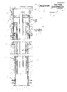
Referring to Fig. 1, wellhead 11 is schematically shown and may
be of various configurations. Wellhead 11 is located at the surface or upper
end of a well for controlling flow from the well. Wellhead 11 is mounted to a
string of conductor pipe 13, which is the largest diameter casing in the well.
A
string production casing 15 is supported by wellhead 11 and extends to a
greater depth than conductor pipe 13. There may be more than one string of
casing within conductor pipe 11. In this example, production casing 15 is
perforated near the lower end, having perforations 17 that communicate a
gas bearing formation with the interior of production casing 15. A casing
hanger 19 and packoff support and seal the upper end of production casing
CA 02356037 2004-04-13
15 to wellhead 11. Conductor pipe 13 and production casing 15 are
cemented in place.
In this embodiment, a string of production tubing 21 extends into
casing 15 to a point above perforations 17. Tubing 21 has an open lower end
for receiving flow from perforations 17. Tubing hanger 23 supports the string
of tubing 21 in wellhead 11. A packoff 25 seals tubing hanger 23 to the bore
of wellhead 11. Production tubing 21 may be conventional, or it may have a
liner 26 within its bore, as shown in Figure 1 a. Liner 26 is a reflective
coating
facing inward for retaining heat within tubing 21. Liner 26 may be made of
plastic with a thin metal film that reflects heat loss back into the interior
of
tubing 21. Alternately, liner 26 may be a plating on the inside of tubing 21
of a
very thin layer of nickel, chrome or other highly reflective coating.
Furthermore, in addition or in the alternative, a heat reflective plating or
liner
28 of similar material could be located on the inner diameter of casing 15.
In the embodiment shown in Fig. 1, a string of coiled tubing 27
extends into tubing 21 to a selected depth. The depth need not be all the way
to the lower end of production tubing 21. Coiled tubing 27 is a continuous
string of pipe of metal or other suitable material that is capable of being
wrapped around a reel and deployed into the well. Production tubing 21, on
the other hand, is made up of individual sections of pipe, each about 30' in
length and secured together by threads. Coiled tubing 27 has a closed lower
end 29 and thus the interior is free of communication with any of the
production fluids. Coiled tubing hanger 31 and packoff 33 seal and support
coiled tubing 27 in the bore of wellhead 11.
An electrical cable 34 is located inside coiled tubing 27, as
illustrated in Figs. 2-4, thus coiled tubing 27 may be considered to be a
metal
jacket that is a part of electrical cable 34. Electrical cable 34 is installed
in
coiled tubing 27 while the coiled tubing is stretched out horizontally on the
surface. It may be installed by pumping through a chase line, then pulling
electrical cable 34 into coiled tubing 27 with the chase line. Electrical
cable 34
is of a type that is adapted to emit heat when supplied with power and may be
constructed generally as shown in US 5,782,301. A voltage controller 37
supplies power to electrical cable 34 to cause heat to be generated.
CA 02356037 2004-04-13
-5-
Referring to Fig. 2, in the first embodiment, electrical cable 34
has a plurality of insulated conductors 39 (three in the preferred embodiment)
and an outer wrap of armor 41. Armor 41 comprises a metallic strip that is
helicaliy wrapped around insulated conductors 39. Electrical cable 34 does
not have the ability to support its own weight in most gas wells. Anchoring
devices are employed in this embodiment to transfer the weight of cable 34 to
coiled tubing 27. The anchoring devices in this embodiment comprise a
plurality of clamps 43 are secured to armor 41 at various points along the
length of electrical cable 34. A plurality of dimples 45 are formed in coiled
tubing 27 above and below each of the clamps 43. While in a vertical
position, the weight of electrical cable 34 will be transferred from clamps 43
to
dimples 45, and thus to coiled tubbing 27. A weldment 47 is filled in each
dimple 45 on the outer surface of coiled tubing 27 to provide a smooth
cylindrical exterior for snubbing operations. There are other types of
anchoring devices available for transferring the weight of electrical cable 34
to
coiled tubing 27.
Referring to Fig. 3, insulated conductors 39 are secured
together at the lower end at a lower termination 49. At lower termination 49,
insulated conductors 39 will be placed in electrical continuity with each
other.
Lower termination 49 is wrapped with an insulation. Also, in the first
embodiment, a dielectric liquid 51 is located in coiled tubing 27 in a chamber
53 at closed lower end 29.
Fig. 4 illustrates more details of electrical cable 34. Each
insulated conductor 39 has a central copper conductor 55 of low resistivity.
In
this embodiment, the insulation includes two layers 57, 59 around each
copper conductor 55. The inner layer 57 in this embodiment is a polyamide
insulation while the outer layer 59 is a polyamide insulation. A lead sheath
61
is extruded around insulation 59 for assisting in conducting heat. Lead sheath
61 is in physical contact with armor 41. The three insulated and sheathed
conductors 55 are twisted together. Cavities 62 exist along electrical cable
34
within armor 41 and between insulated conductors 39. Cavities 62 are
CA 02356037 2001-08-28
-6-
preferably filled with the dielectric liquid 51 (Fig. 3) for conducting heat
away
from insulated conductors 39. Similarly, an inner annulus 63 surrounds armor
41 within coiled tubing 27. Inner annulus 63 is filled with the same
dielectric
liquid 51 (Fig. 3) as in cavity 62 because armor 41 does not form a seal. The
dielectric liquid 51 in inner annulus 63 assists in transferring heat away
from
cable 34. This not only enhances heat transfer to gas flowing within the well
but also avoids excessive heat from damaging electrical cable 34.
Referring again to the embodiment of Fig. 1, a siphon tube 65
leads from a syphon reservoir 67 to inner annulus 63. Siphon tube 65
extends laterally through a port in wellhead 11. Reservoir 67 contains
dielectric fluid 51 (Fig. 3) and is typically located above the upper end of
coiled tubing 27. Thermal expansion will cause dielectric liquid 51 to flow
into
siphon tube 65 and up into reservoir 67. When power to electrical cable 34 is
turned off, the resulting cooling will cause dielectric fluid 51 to flow out
of
reservoir 67 and back through siphon tube 65 into coiled tubing 27.
Referring still to Fig. 1, an intermediate annulus 69 surrounds
coiled tubing 27 within production tubing 21. This constitutes the main
production flow path for gas from the well, the gas flowing out intermediate
annulus 61 and through a flow line 71 that contains a valve 73. Also, an outer
annulus 75 surrounds production tubing 21. A packer 78 seals production
tubing 21 to production casing 15 near the lower end of tubing 21, forming a
closed lower end for outer annulus 75.
A port 77 extends through wellhead 11 in communication with
outer annulus 75. Port 77 is connected to a line that has a valve 79 and leads
to a vacuum pump 80. Vacuum pump 80, when operated will create a
vacuum or negative pressure less than atmospheric within outer annulus 75.
The vacuum created within outer annulus 75 comprises a fluid of low thermal
conductivity and low density to reduce heat loss from tubing 21 to the earth
formation. Alternately, the fluid of low thermal conductivity within outer
annulus 75 could be a liquid of low thermal conductivity and preferably high
viscosity such as a crude oil with a viscosity of 1000 centipoise or higher.
CA 02356037 2001-08-28
-7-
Many gas wells are in remote sites not served by electrical
utilities. In such cases, some of the gas production from tubing 21 could be
used to power an engine driven electrical generator. The electricity from the
generator would be used to power heater cable 34.
Briefly discussing the operation, voltage controller 37 will deliver
and control a supply of electrical power to electrical cable 34. This causes
heat to be generated, which warms gas flowing from perforations 17 up
intermediate annulus 69. The amount of heat is sufficient to raise the
temperature of the gas to reduce condensation levels that are high enough to
restrict gas flow. The temperature of the gas need not be above its dew point,
because it will still flow freely up the well so long as large droplets do not
form,
which fall due to gravity and restrict gas flow. Some condensation can still
occur without adversely affecting gas flow. The amount of heat needs to be
only enough to prevent the development of a large pressure gradient in the
gas flow stream due to condensation droplets.
The dew point is the temperature and pressure at which liquid
vapor within the gas will condense into a liquid. The condensate may be a
hydrocarbon, such as butane, or it may be water, or a combination of both. If
significant condensate forms in the well, large droplets and slugs of liquid
develop, which create friction. The friction drops the pressure and lowers the
production rate. Preferably, heater cable 34 supplies enough heat to
maintaining the gas at a temperature sufficient to prevent frictional losses
due
to formation of condensate. The gas can be below the dew point in a cloudy
state without detriment to the flow rate because large droplets of condensate
are not produced in the cloudy state . Eliminating condensate that causes
frictional losses allows the pressure to remain higher and increases the rate
of production. The water and hydrocarbon vapors that remain in the gas will
be separated from the gas at the surface by conventional separation
equipment.
Figs. 5 and 6 represent measurements of a test well in which a
heater cable was employed. Fig. 5 is a graph of pressure versus the depth of
the well without heat being supplied by heater cable 34 (Fig. 1 ). Plot or
curve
CA 02356037 2001-08-28
_8-
81 represents pressure data points taken at various depths in the well while
the well was not flowing, rather was shut in and live. That is, it had
pressure
at wellhead 11 of approximately 108 PSI but valves were closed to prevent
the gas from flowing. The plot is substantially a straight line. Plot or curve
83
represents pressure monitored at various depths while the well was flowing,
but still without heat being supplied by heater cable 34. Note that the
flowing
plot 83 parallels shut-in plot 81 generally from the total depth to
approximately
3000'. The pressure from 6000 feet to 3000 feet is approximately 3 to 5 PSI
less while flowing, but generally on the same slope as while shut-in. At about
3000 feet, plot 83 changes to a much shallower slope. The slope from about
3000 to 1000 feet is still linear, but is substantially shallower than the
slope of
shut-in plot 81. There is a sharp increase in slope around 800 to 1000 feet,
then plot 83 resumes its shallow slope until reaching wellhead 11. The slope
of flowing plot 83 changes at point 87, which is the point along the
production
tubing 21 where liquid droplets have collected in sufficient quantities to
cause
a large increase in pressure gradient. Significant condensation is occurring
at
point 87, which thus drops the pressure and flow rate from 3000 feet up. The
condition at and above point 87 is created by water droplets falling downward
due to gravity and then collecting in slugs, which greatly restrict flow.
Production gasses either have to bubble through the water slugs or the water
slugs have to be pushed up the well by gas pressure. The dashed line
extending from point 87 upward at the same slope as the lower portion of
flowing plot 83 indicate the theoretical pressures that would occur along the
well from 3000 feet to the surface if condensation were not occurring. The
pressure at the surface would be approximately 95 PSI rather than 60 PSI,
thus resulting in a greater flow rate. The greater flow rate not only enables
an
operator to produce faster for additional cash flow but also may prevent a
well
from being abandoned because of a low flow rate, the abandonment resulting
in residual gas remaining in the formation that does not get produced. The
purpose of heater cable 34 (Fig. 1 ) is to apply enough heat to cause plot 83
to
remain more nearly linear at the same slope as in the lower portion.
CA 02356037 2001-08-28
_g_
A video camera was also run through the well being measured
in Fig. 5, and it confirmed that substantial condensation droplets existed
approximately at the depths from 3000 feet to 1000 feet. Plots 81, 83 were
made in a conventional manner by lowering a pressure monitor on a wire line
into the well.
Fig. 6 is a graph of depth versus temperature of a well with heat
being supplied by heater cable 34 and without heat being supplied. Plot 89 is
an actual measurement of the temperature gradient while the well was flowing
but without heater cable 34 supplying heat. This plot was obtained by
measuring the temperature at various points along the depth of the well. Plot
89 is approximately linear and differs only in slight amounts from a
geothermal
gradient of the well. Plot 91 represent temperature measurements made
while heater cable 34 (Fig. 1 ) was being supplied with power. The
temperature is considerably greater throughout the well, being about 60 to
80 higher than without power being supplied to heater cable 34. The
temperature difference depends on the structure of electrical cable 34 as well
as the amount of power being supplied to electrical cable 34. The test also
showed that the gas flow rate increased substantially when heated as
indicated by plot 91 in Figure 6. Condensate in the well was reduced greatly,
the pressure at the surface increased, and the flow rate increased
significantly. In one well, gas flow increased from about 100 mcf (thousand
cubic feet) to 500-600 mcf. The temperature difference in that well average
about 75 degrees over the length of heater cable 34.
As mentioned, it is not necessary to maintain the gas at a
temperature and pressure far above its dew point, rather the temperature
should be only sufficient to avoid enough condensation that causes significant
frictional losses. The well needs to be heated an amount sufficient to reduce
droplets of condensation and thus the friction caused by them. Further, it may
not be necessary to add as much heat in the upper portion of the well, such
as the upper 1000 feet, because there will be insufficient residence time in
this section for droplets to build up in sufficient quantity to cause any
significant increase in pressure gradient. That is before condensation
CA 02356037 2001-08-28
-10-
droplets have time to fall downward and form water slugs in the flow stream,
they will have exited the well. Increasing the temperature far above the dew
point would not be economical because it requires additional energy to create
the heat without reducing the detrimental pressure gradient. The flow rate or
gas pressure at wellhead 11 can be monitored at the surface and power to
heater cable 34 varied accordingly by controller 37. For example, the power
could be reduced or turned off until the flowing pressure decreased a
sufficient amount to again begin supplying power. Alternately, downhole
sensors could be employed that monitor the temperature and/or pressure
within the production tubing and turn the power to the heater cable on and off
accordingly. Furthermore, when applying a vacuum to the tubing annulus 75,
particular when using heat reflective liners 26 or 28 (Fig. 1 a), it may not
be
necessary to utilize heater cable 34 to apply heat. When heat losses to the
earth formation are greatly reduced in this manner, the gas flowing through
production tubing 21 may have enough heat within it to avoid detrimental
condensation. In some cases, heater cable 34 may be necessary for
heating only initially or occasionally.
There are a number of variations to different components of the
system. Figure 7 shows a transverse cross section of an alternate lower
termination to the one shown in Figure 3. A copper block 92 is crimped
around the three copper conductors 52, shorting them together. A canister or
sheath 93 encloses block 92 and conductors 52. An insulating compound 94
is filled in the spaces surrounding conductors 52 and block 92. In the
embodiment of Figure 7, dielectric liquid 51 (Figure 3), reservoir 67 and
siphon tube 65 are not required.
Figure 8 shows a heater cable that is constructed generally as
shown in US Pat. 6,103,031. The three insulated conductors 55 are twisted
together and located within a spacer or standoff member 95 that has three
legs 95a spaced 120 degrees apart and a central body 95b. Conductors 55
are located within central body 95b. Standoff member 95 is preferably a
plastic material extruded over the twisted conductors 55 and is continuous
along the lengths of conductors 55. A metal tubing 96 extends around
CA 02356037 2001-08-28
-11-
standoff member 95. An insulation filler material 97 may surround standoff
member 95 within tubing 96.
An advantage of the heater cable of Figure 8 is the small
diameter of tubing 96 that is readily achievable. A larger diameter for the
heater cable reduces the cross-sectional flow area for the gas flow up
production tubing 21 (Fig. 1 ). The heater cable of Figure 8 has an outer
diameter no greater than one inch, and may be as small as one-half inch.
To manufacture the heater cable of Figure 8, conductors 55 are
formed within standoff member 95 and placed along a strip of metal. The
metal is bent into a cylindrical configuration and welded to form the tubing
96.
Legs 95a of standoff member 95 position conductors 55 away from the
sidewall of tubing 96 to avoid heat damage during welding. Filler material 97
may be pumped into tubing 96 after it has been welded.
In the heater cable embodiment of Figure 9, an elastomeric
jacket 98 is extruded over insulated conductors 55. Jacket 98 is placed on a
flat metal strip, which is bent and welded at seam 100 to form tubing 93. The
inner diameter of tubing 93 is initially larger than the outer diameter of
jacket
98, although the difference would not be as great as illustrated in Figure 9.
Then tubing 93 is swaged to a smaller diameter as shown in Figure 10, with
the inner diameter of tubing 93 in contact with the outer diameter of jacket
98.
Having an initial larger diameter allows conductors 55 and jacket 98 to be
located off center of the center of tubing 93 during the welding process.
Seam 100 can be located on an upper side of tubing 93, while jacket 98
contacts the lower side of tubing 93 due to gravity. This locates conductors
55 farther from weld 55 while weld 55 is being made than if conductors 55
were on the center of tubing 93. This off center placement reduces the
chance for heat due to welding from damaging conductors 55. After swaging,
the center of the assembly of conductors 55 will be concentric with tubing 93,
as shown in Figure 10. The heater cable of Figure 10 also has an outer
diameter in the range from one-half to one inch.
Fig. 11 shows a single phase conductor 99, rather than the three
phase electrical cable 34 of Fig. 4. Also, this heater cable does not have an
CA 02356037 2001-08-28
-12-
outer armor and is not located within coiled tubing. The heater cable of
Figure 11 includes a copper conductor 99 of low resistivity. An electrical
insulation layer 101 surrounds conductor 99, and is exaggerated in thickness
in the drawing. Because of the depth of most gas wells, a strengthening
member 103 is formed with around layer 101 to prevent the heater cable from
parting due to its own weight. The strengthening member 103 could be
aramid fiber or metal of stronger tensile strength than copper, such as steel.
In this embodiment, strengthening member 103 surrounds insulation layer
101, resulting in an annular configuration in transverse cross action. An
elastomeric jacket 105 is extruded over strengthening member 103 to
provide protection. If desired, the return for the single phase power could be
made through strengthening member 103, which although not as a good of a
conductor as copper conductor 99, will conduct electricity.
Because of its ability to support its on weight, the heater cable of
Figure 11 would be deployed directly in production tubing 21 (Fig. 1 ) without
coiled tubing 27. In shallow wells, say less than about 5000 feet, it may not
be necessary to use a strengthening member. Rather, the copper conductor
99 could be formed of hard drawn copper or a copper alloy such as brass or
bronze, rather than annealed copper, adding enough strength to support the
weight of the cable in shallow wells. The outer diameter of the heater cable
of Figure 11 is preferably from one-half to one inch.
In Fig. 12, the outer configuration of the heater cable is shown to
be flat, having two flat sides and two oval sides, rather than cylindrical.
However, electrical cable 106 could also have a cylindrical configuration.
Electrical cable 106 is also constructed so as to be strong enough to support
its own weight. It has three separate copper conductors 107, thus is to be
supplied with three phase power. It has strengthening members 109
surrounding and twisted with each of the copper conductors 107. Each
strengthening member 109 may be of conductive metal, such as steel or of a
non-conductor such as an aramid fiber. Strengthening members 109 have
greater tensile strength than copper conductors 107. An elastomeric jacket
111 surrounds the three assemblages of conductors 107 and strengthening
CA 02356037 2001-08-28
-13-
members 109. It is not necessary to have outer armor. Coiled tubing will not
be required, either.
Fig. 13 shows another variation for electrical cable in lieu of
electrical cable 34. Fig. 13 schematically illustrates an electrical cable 113
within a well, with the well depths listed on the left side. The amount of
heat
required at various points along the depth of the well is not the same in all
cases. In some portions of the well, the gas may be near or above the dew
point naturally, while in other points, well below the dew point.
Consequently,
it may be more feasible to supply less heat in certain portions of the well
than
other portions of the well to reduce the consumption of energy.
In Fig. 13, electrical cable 113 may be of any one of the types
shown in Figs. 2, 4, 7-10 or any other suitable type of electrical cable for
providing heat. However, portions of the length of the electrical cable 113
will
have different properties than others. For example, portion 113a, which is at
the lower end, may be made of larger diameter conductors than the other
portions so that less heat is distributed and less power is consumed. Portion
113b may have smaller conductors than portion 113a or 113c. Portion 113b
would thus provide more heat due to the smaller conductors than either
portion 113a or 113c. Similarly, portion 113c may have larger conductors
than portion 113b but smaller than portion 113a. This would result in an
intermediate level of heat being supplied in the upper portion of the well.
There are other ways to vary the heat transfer properties other than by
varying the cross sectional dimensions. Changing the types of insulation or
types of metal of the conductors will also accomplish different heat transfer
characteristics.
Fig. 14 illustrates a variation of the system of Fig. 1. Some
water may also be produced from the formation along with saturated gas, and
this water collects in the bottom of the well. If too much water collects in a
low
pressure gas well, it can greatly restrict the perforations and even shut in
the
well. In the system of Fig. 14, a pump 115 is located at the bottom of the
well.
In this example, pump 115 is secured to the lower end of coiled tubing 117.
Pump 115 has an intake 119 for drawing liquid condensate in that is collected
CA 02356037 2001-08-28
-14-
in the bottom of the well. Pump 119 need not be a high capacity pump, and
could be a centrifugal pump, a helical pump, a progressing cavity pump, or
another type. Preferably, pump 115 is driven by an electrical motor 121. The
electrical power line 123 is preferably connected to electrical cable 125 that
also supplies heat energy for heating the gas. A downhole switch (not shown)
has one position that connects line 123 to cable 125 to supply power to pump
115. The switch has another position that shorts the terminal ends of the
three conductors of cable 125 to supply heat rather than power to pump 115.
In the embodiment of Figure 14, heater cable 125 has a continuous annulus
127 surrounding it within coiled tubing 117. Preferably, pump 115 will have
its discharge connected to coiled tubing 117 for flowing the condensate up the
inner annulus 127. The flow discharges out the open upper end of coiled
tubing 117 and flows out a condensate flow line 129 leading from the
wellhead. Gas will be produced out production tubing 131. A vacuum pump
connected to port 133 will reduce the pressure within the annulus surrounding
production tubing 134. A voltage controller 135 will not only control the heat
applied to electrical cable 125, but also control turning on and off the
downhole switch at pump motor 121. Additionally, if desired, a surface
actuated isolation valve 136 can be placed between pump 119 and the interior
of coiled tubing 117 so that the system can be deployed in a live well without
fear that gas will enter coiled tubing 117 and flow to the surface.
Automatic controls can be installed on the surface to shut off the
heater cable function and activate pump motor 121 whenever excessive water
builds up in the well. This condition can be determined by evaluating
pressure and flow rate conditions on the surface, by scheduling regular
pumping periods to keep the well dry, or by measuring the pressure at the
bottom of the well directly with instruments installed at the bottom of the
assembly. A downhole pressure activated switch or other suitable means can
be employed to automatically cut off pump motor 121 when the condensate
drops below intake 119.
Fig. 15 represents a preferred method of installing the system
shown in Fig. 1. The system of Fig. 1 is live well deployable. That is,
CA 02356037 2001-08-28
-15-
pressure will still exist at wellhead 11 while coiled tubing 27 is being
inserted
into the well, although production valves 73, 79 may be closed in. It is
important to be able to install heater cable 34 (Fig. 1 ) while the well is
live to
avoid having to kill the well to install the new system. Killing low pressure
gas
wells is a very risky business because there is a good chance that the
operator will not get the well back. When the reservoir energy is low, there
may be insufficient pressure to push the kill fluid out of the formation
and/or
water may flow into the well faster than it can be swabbed out. If this
happens, the well cannot be recovered and all production is lost. By
installing
the system in a live well, the risk of losing the well is avoided.
The preferred method of Fig. 12 utilizes a pressure controller,
which is a snubber or blowout preventer 137 of a type that will seal on a
smooth outer diameter of a line, such as coiled tubing 27 or the heater cables
of Figures 7 - 12, and allow it to simultaneously be pushed downward into the
well. Blowout preventer 137 is mounted to wellhead 11 and has an injector
139 mounted on top. Injector 139 is of a conventual design that has rollers or
other type of gripping members for engaging coiled tubing 27 and pushing it
into the well. Blowout preventer 137 simultaneously seals on the exterior of
coiled tubing 27 in this snubbing type of operation. Electrical cable 34 (Fig.
1 )
will be installed in coiled tubing 27 at the surface, then coiled tubing 27 is
wrapped on a large reel 141. Reel 141 is mounted on a truck that delivers
coiled tubing 27 to the well site. It is important that coiled tubing 27 be
smooth
on the outside for the snubbing operation through blowout preventer 137.
This system of Fig. 15 could also be utilized with electrical
cables types that have the ability to support their own weight and are not
within coiled tubing, such as shown in Figs. 11 and 12. The heater cables of
Figures 11 and 12 are brought to the well site on a reel and deployed through
stripper rubbers of blowout preventer 137. The heater cables of Figures 11
and 12 must be impervious to the flow of gas and be able to support their
own weight when suspended from the top of well during installation and
operation. A sinker or weight bar can be attached to the lower end of the
CA 02356037 2001-08-28
-16-
heater cables of Figures 11 and 12 to help the cables to slide down the well
without getting caught.
Fig. 16 illustrates another live well deployable system. In Fig.
16, a coiled tubing injector is not required for installing the heater cable.
Rather, a wireline deployable plug 145 will be installed first in production
tubing 143. The installation of plug 145 can be done by conventional
techniques, using a blowout preventer with a stripper that enables plug 145 to
be snubbed in. Once plug 145 is deployed, the wire line is removed. The
interior of production tubing 143 will now be isolated from the pressure in
casing 146. The operator then lowers a heater cable assembly 147 into
production tubing 143. Heater cable assembly 147 may comprise coiled
tubing having an electrical cable such as in any of the embodiments shown, or
it may be a self-supporting type as in Figures 11 and 12. Once fully deployed
in the well, heater cable assembly 147 is sealed at the surface. Then, plug
145 will be released. The releasing of plug 145 will communicate gas to the
interior of production tubing 143 again. The releasing may be accomplished
in different manners. One manner would be to apply pressure from the
surface to cause a valve within plug 145 to release. Another method might be
to pump a fluid into the well that will destroy the sealing ability of plug
145.
Fig. 17 shows another type of heater cable assembly that could
be employed in lieu of coiled tubing supported heater cable 34 (Figs. 1 and 7-
10) or self-supporting heater cables of Fig. 11 and 12. It would be employed
in production tubing 143 (Fig. 13) or in another conduit that is isolated from
well pressure by plug 145. Heater cable 149 is strapped to a string of sucker
rod 153 or some other type of tensile supporting member. Heater cable 149
may be electrical cable such as shown in US 5,782,301. Sucker rod 153
comprises lengths of solid rod having ends that are screwed together. Sucker
rod 153 is commonly used with reciprocating rod well pumps. Straps 152 will
strap electrical cable 149 to the string of sucker rod 153 at various points
along the length. The assembly of Fig. 16 is lowered in production tubing 143
of Fig. 16, then plug 145 is released.
CA 02356037 2001-08-28
-17-
Another embodiment, not shown, may be best understood by
referring again to Fig. 1. In Fig. 1, electrical cable 34 is installed in
coiled
tubing 27 at the surface prior to installing coiled tubing 27 in the well with
injector 139. Alternately, self-supporting electrical cable, such as the
embodiments of Figs. 11 and 12, could be installed in coiled tubing 27 after
it
has been lowered in place. Because coiled tubing 27 has a closed lower end
29, it will be isolated from pressure within production tubing 21. Self
supporting cable, such as those shown in Figs. 11 and 12, could be lowered
into coiled tubing 27 from another reel. A weight or sinker bar could be
attached to the end of the heater cable.
Figure 18 illustrates still another method of installing heater
cable within a live well, particularly a well that does not have a packer
already
installed between the tubing and the casing. The well has a production
casing 157 cemented in place. Production tubing 159 is suspended in casing
157, defining a tubing annulus 161. Unlike Figure 1, there is no packer
located near the lower end of tubing 159 to seal the lower end of tubing
annulus 161. To prepare for a live well installation of heater cable, a hanger
mandrel 163 is lowered into tubing 159 and set near the lower end of tubing
159. A locking element 165 will support the weight of hanger mandrel 163.
Seals 167 on the exterior of mandrel 163 seal mandrel 163 to the interior of
tubing 159. Seals 167 may be energized during the landing procedure of
mandrel 163 in tubing 159.
Typically mandrel 163 has an extension joint 169 extending
below it. A packer 171 is mounted to extension joint 169. Packer 171 has a
collapsed configuration that enables it to be lowered through tubing 159, and
an expanded position that causes it to seal against casing 157, as shown.
Once packer 171 has set, tubing annulus 161 will be sealed from production
flow below packer 171. Hanger mandrel 163 has an interior passage that
allows gas flow from the perforations below packer 171 to flow up production
tubing 159.
Hanger mandrel 163 may be lowered by a wireline, which is
then retrieved. Although pressure will exist in tubing 159 while hanger
CA 02356037 2001-08-28
-18-
mandrel 163 is being run, a conventional snubber will seal on mandrel 163
and the wireline to while being run. When hanger mandrel 163 has landed
within tubing 159, packer 171 will be located below the lower end of tubing
159. The operator then sets packer 171 in a conventional manner. Heater
cable 175, which may be any one of the types described, is lowered into
production tubing 159 to a point above mandrel 163 by using a snubber at the
surface. Packer 171 allows the operator to draw a vacuum in tubing annulus
161 by a vacuum pump at the surface, so as to provide thermal insulation to
tubing 159. The operator supplies power to heater cable 175 to heat gas
flowing up tubing 159.
Prior to installing heater cable with any of the methods
described above, calculations of the amount of energy to be deployed should
be made. Pressure and temperature surveys should be made to determine
the depth at which the water is building up in the tubing, causing the
pressure
gradient to greatly increase. The heat transfer rate to raise the production
fluid temperature by the required amount is calculated. In order to do this,
one must determine the heat transfer coefficient at the outer diameter of the
coiled tubing 27 (Fig. 1 ). The temperature needed at the outer diameter of
the coiled tubing 27 to supply the required heat transfer rate is calculated.
The heat transfer resistance from the coiled tubing 27 to casing 15 (Fig. 1 )
is
determined. The heat transfer resistance from the heated production fluid to
casing 15 is calculated. The heat transfer resistance from casing 15 to the
earth formation is calculated. All of the heat transfer resistances are
summed.
The heat transfer coefficient for fluid inside of coiled tubing 27 to
the inner diameter of coiled tubing is determined. The temperature of fluid
inside coiled tubing 27 to deliver the summed heat transfer rate is
determined.
The heat transfer coefficient at heater cable 34 (Fig. 4) surface is
determined.
The temperature of the heater cable surface 34 to deliver the summed heat
transfer rate is calculated. The heat transfer coefficient from heater cable
conductors 55 (Fig. 4) to heater cable outer surface 41 is calculated. The
temperature of heater cable conductors 55 to deliver the summed heat
transfer rate is calculated. The electrical resistance of the heater cable
CA 02356037 2001-08-28
-19-
conductors is measured. The amperage need to deliver the watt equivalent of
the summed heat transfer rate is computed. The applied voltage needed to
cause the desired amperage in the heater cable is then calculated.
The invention has significant advantages. Deploying the heater
cable while the well is live avoids the risk of not being able to revive the
well if
it is killed. Once deployed, the heat generated by the heater cable reduces
condensation, increasing the pressure and flow rate of the gas.
While the invention has been shown in only a few of its forms, it
should not be limited to the embodiments shown, but is susceptible to various
modifications without departing from the scope of the invention.