Note: Descriptions are shown in the official language in which they were submitted.
CA 02356105 2004-12-10
FUNCTIONAL UNIT WITH POSITIONING DEVICE
BACKGROUND OF THE INVENTION
1. Field of the Invention
The invention relates to a rotary printing machine such as a web-fed rotary
printing machine, having a printing unit comprised of a plurality of printing-
unit
cylinders at least one of which can be brought into and out of contact with a
functional unit associated with a function needed to operate the printing
unit.
2. Description of the Related Art
In the case of arrangements of the type present here, there are infeed
movements between the printing-unit cylinders and the functional units
associated with these. In the case of the known rotary printing machines, the
infeed movements between mutually associated elements are generally
implemented in each case by means of a pivoting movement limited by
mechanical stops. The drawback in this case is that the stops have to be
adjusted and readjusted in the event of changing conditions. The result is,
therefore, a high operational outlay. Added to this is the fact that many
conditions, such as the temperature of printing cylinders, change frequently
or
continuously, so that exact readjustment with tolerable effort is not even
possible.
The consequence of this is inaccurate setting, which has a detrimental effect
on
the achievable working result.
SUMMARY OF THE INVENTION
It is an object of the present invention to provide a rotary printing machine
of the above-mentioned type while avoiding the disadvantages of the known
arrangements and in which high operating convenience and accuracy are
ensured.
This object is achieved by providing a rotary printing machine, in particular
a web-fed rotary printing machine, having at least one printing unit which
comprises a plurality of printing-unit cylinders, of which at least one can be
brought into and out of operative connection with at least one functional unit
which is associated with a function needed to operate the printing unit, the
1
CA 02356105 2007-05-07
functional unit being provided with a drive device, and fitted on a linear
guide
device. The functional unit is assigned a positioning device, which has a
controller which can be fed with at least one position-dependent signal that
can
be generated by means of a sensor arrangement associated with the functional
unit and by which the drive device can be controlled.
These measures make it possible to dispense with mechanical stops, so
that the disadvantages associated with these are also advantageously dispensed
with. The positioning device according to the invention advantageously permits
exact positioning of the associated functional unit in any desired position,
it being
possible for automatic adaptation to changing conditions to take place. This
advantageously also applies to changing cylinder diameters, which makes it
easier to change format.
In accordance with a broad aspect of the present invention, there is
provided a rotary printing machine, comprising: a printing unit including a
plurality
of printing-unit cylinders; at least one functional unit associated with a
function
needed to operate the printing unit, the functional unit being brought into
and out
of connection with at least one of the printing unit cylinders; a linear guide
device
on which the functional unit is fitted for movement in a linear direction with
respect to the one printing-unit cylinder, at least part of the functional
unit is fitted
with frame-side ends on guide rails fitted to side walls of a machine frame,
the
rails forming the linear guide device; a drive device for moving the
functional unit
on the linear guide device; a sensor arrangement associated with each the
functional unit for generating a position-dependent signal; and a positioning
device associated with each the functional unit and including a controller,
the
controller controlling the drive device responsive to the position-dependent
signal,
wherein the sensor arrangement includes a sensor operative for sensing a
functional unit travel distance when the drive device is activated and
outputting a
sensed travel distance signal to the controller, and another sensor for
sensing a
travel encounter of the functional unit with the one printing-unit cylinder
and
outputting an encounter signal to the controller.
Other advantageous refinements and expedient developments of the
higher-order measures can be made. For example, the functional unit can
expediently be associated with sensor arrangements for determining the
2
CA 02356105 2007-05-07
respective distance covered and the encounter with the associated printing-
unit
cylinder, it being possible for the output signals from the sensor
arrangements to
be fed to the controller. The combination of distance-based and point-based
control results in particularly high accuracy when moving to a desired
operating
position.
The controller can advantageously be programmed in such a way that the
functional unit can be moved into a desired operating position when the drive
device is activated, starting from the position determined when it encounters
the
associated printing-unit cylinder. The position in which the functional unit
encounters the associated printing-unit cylinder forms a zero point or
reference
point which the functional unit looks for in every case, so that an exact
operating
position can always be reached, irrespective of the position of this reference
point. Moving the functional unit to a desired position also can involve a
setting to
a desired contact pressure or a desired gap width with respect to an
associated
printing-unit cylinder.
The sensor arrangement for determining the distance covered may
expediently be associated with an incremental arrangement. In this case,
digital
values, which can easily be processed as data, automatically result.
2a
CA 02356105 2001-08-29
A further advantageous refinement of the higher-order measures can
consist in the sensor arrangement for determining the encounter between the
functional unit and the associated printing-unit cylinder being designed as a
strain
detector associated with a part of the drive device which can be acted on by
the
contact pressure between functional unit and printiing-unit cylinder. This
detector
advantageously supplies a signal which is an analog of the contact pressure.
The
result is therefore simultaneously a pressure sensor. This makes it easier to
drive
the drive device in order to reach an operating position, in which the
functional
unit is thrown with pressure onto the associated printing-unit cylinder.
Setting the
functional unit to a gap with respect to the associated printing-unit cylinder
is, by
contrast, expediently carried out as a function of disitance.
In a further development of the higher-orcler measures, the controller,
which is expediently designed as a programmable computer, can have a
communications connection for a remote programn-iing and/or monitoring device.
This advantageously permits the rectification of maladjustments, etc., by
using
modern communication means, which results in extreme ease of maintenance
and servicing.
The various features of novelty which characterize the invention are pointed
out with particularity in the claims annexed to and forming a part of the
disclosure.
For a better understanding of the invention, its operating advantages, and
specific
objects attained by its use, reference should be had ~to the drawing and
descriptive
matter in which there are illustrated and described lpreferred embodiments of
the
invention.
Other objects and features of the present invention will become apparent
from the following detailed description considered in conjunction with the
accompanying drawings. It is to be understood, however, that the drawings are
designed solely for purposes of illustration and not as a definition of the
limits of
the invention, for which reference should be made to the appended claims. It
should be further understood that the drawings are riot necessarily drawn to
scale
and that, unless otherwise indicated, they are merely intended to conceptually
illustrate the structures and procedures described herein.
3
CA 02356105 2001-08-29
BRIEF DESCRIPTION OF THE DRAWINGS
Figure 1 shows a schematic view of a pirinting unit of a web-fed rotary
printing machine according to the invention; and
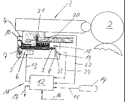
Figure 2 shows a functional unit of thie arrangement according to
Figure 1 with associated drive, guide and positioning devices.
DETAILED DESCRIPTION OF THE PRESENTLY PREFERRED EMBODIMENTS
The fundamental construction and mode of action of rotary printing
machines, such as web-fed rotary printing machines, are known per se and
therefore do not require any more detailed explanation in the present
connection.
The printing unit on which Figure 1 is based comprises a machine frame 1, on
which there are mounted a plurality of printing-unit cylinders 2 which
interact in a
manner known per se and here form a double printing unit. Associated with the
cylinders are various devices needed to operate tlhe printing machine, such as
inking units, damping units, washing devices, image-setting devices, fixing
devices, erasing devices. These devices in each case form a functional unit 3
which can be inserted into the printing unit, can be preassembled completely
outside the machine and is intrinsically adjustable.
At least part of the functional units 3 is in each case fitted with the frame-
side ends on guide rails 4 fitted to the side walls of the machine frame 1,
the rails
forming a linear guide device. These functional units 3 are therefore
adjustable in
the linear direction with respect to the respectively associated printing-unit
cylinder 2.
Each of these linearly adjustable functional units 3 is provided with a drive
device 5 illustrated in more detail in Figure 2. The drive device comprises an
electric drive motor 6 which is fixed to the machine f'rame 1 and, via a lay
shaft 7,
drives a threaded spindle 9 which is mounted on bearing plates 8 fitted to the
machine frame 1 and which can be brought into engagement with a threaded nut
10 fitted to the associated functional unit 3. The nut can be a half-open
threaded
nut, so that simple disengagement of functional unit 3 and frame-side drive
device 5 is possible, which makes the insertion or removal of the functional
unit 3
particularly simple.
4
CA 02356105 2001-08-29
The'drive motor 6, which may be a DC motor, can be controlled by means
of a positioning device 11, which is associated wiith the functional unit 3
and is
likewise shown in Figure 2. The positioning device comprises a controller 12
which is designed as a programmable computer, into which the desired positions
to which the functional unit 3 is intended to be able to move are input in the
form
of electronic data, and to which measured values corresponding to the
respective
current position of the functional unit 3 are fed in the form of suitable
signals. As a
rule, there are three positions to which the functional unit 3 must move,
namely
an operating position, a thrown-off position and a chiangeover position.
The controller 12 uses the position-dependent signals fed to it to
determine control commands for the drive motor 6, which are transmitted via a
signal line 13. In order to input the values of the positions to which to
move, an
input device 14 is provided, which is connected to the controller 12 via a
signal
line 15. The controller 12 also has an input for a corinection, indicated by a
signal
line 16, to the machine control device, which provides the action commands. In
addition, the controller 12 in the example shown has a remote connection, as
it is
called, which is associated with a signal line 17 via which communication with
the
controller 12 and, therefore, enabling remote programming and/or remote
monitoring, etc. is possible.
The measuring elements for determining the aforementioned position-
dependent measured values comprise a distance measuring device 18, which
measures the distance covered in each case by the functional unit 3, and a
sensing device 19 for sensing the aforementioned zero point, to which the
distance measuring device 18 can make reference. The distance measuring
device 18 contains an incremental element 20, with which a sensor 21 is
associated, which is arranged in such a way that thie result is relative
movement
between the incremental element 20 and sensor 21. The output from the sensor
21 is connected, via a signal line 22, to an associated input of the
controller 12.
The sensing device 19 contains a sensor 23 which, when the functional unit 3
encounters the associated printing-unit cylinder 2, generates a signal which
is
fed, via a signal line 24, to an associated input of the: controller 12.
It is expedient for the zero point, which the positioning device according to
the invention senses automatically in order to provide self-adjustment, as
already
5
CA 02356105 2001-08-29
indicated above, to be defined as the position in which the functional unit 3
runs
with its working element associated with the printing-unit cylinder 2 onto the
associated printing-unit cylinder 2 and touches -the latter. The sensor 23 is
therefore designed in such a way that a signal is output when the associated
functional unit 3 runs onto the associated printing-unit cylinder 2. In the
exemplary embodiment shown, the sensor 23 is designed as a strain gauge,
which is fitted to a bearing plate 8 associated with the threaded spindle 9.
The
force flow for deriving a reaction force on the machine frame 1 that is
exerted by
the printing-unit cylinder 2 when the functional unit 3 runs onto the
associated
printing-unit cylinder 2 flows via the bearing plate 8. In this case, the
bearing plate
8 is stressed in flexure, which increases with increasing contact force and
vice-
versa.
The strain gauge forming the sensor 23 therefore supplies a signal which
is an analog of the contact pressure. The start of this signal virtually
corresponds
to the first contact and therefore to the aforementioned zero point. The
further
course of this signal correlates with the contact pressure. The signal
supplied by
the sensor 23 therefore advantageously contains two items of information,
namely an indication of the contact point, which can be used as the zero
point,
and an indication of the contact pressure, whose accurate maintenance is
desired in many cases.
The controller 12 is programmed here in such a way that the functional
unit 3 can be moved into a desired operating position when the drive device 5
is
activated, starting from the zero point automatically found in the manner
presented above. Since the positioning device 11 always determines the
aforementioned zero point itself as the contact point, the result is automatic
self-
adjustment, changing conditions, for example as a result of temperature
fluctuations, etc., automatically being controlled out. The same also applies
to
different diameters of the printing-unit cylinders 2, so that no adjustment
operations arise, even with a change of format.
Some functional units 3 are thrown onto the associated printing-unit
cylinder 2 with pressure when operating, others are set to a gap from the
associated printing-unit cylinder 2. First of all, in each case the zero
position is
moved to, which corresponds to the contact position at which the operating
6
CA 02356105 2001-08-29
element of'the functional unit 3 encounters the associated printing-unit
cylinder 2.
If a gap is to be set, the drive motor 6 is driven by the controller 12 in
such a way
that the functional unit 3 covers a distance corresponding to the clear gap
width,
starting from the aforementioned zero positiori. The distance covered is
determined exactly by means of the distance measuring device 18, so that the
functional unit 3 comes exactly into the desired position at which the desired
gap
width is present. In order to maintain this gap width over relatively long
time
periods, provision can be made to move to the zero position again from time to
time and to reset the gap width.
When larger editions are being printed, ithis can be carried out, for
example, during the operating interruptions necessitated by the operation, for
example during the stoppages for washing. In the case of smaller editions, one
generally manages with one setting per print job.
The action of transporting the functional uni't 3 into the thrown-off waiting
position or the changeover position, in which the furictional unit 3 can be
removed
or inserted, also proceeds in a similar way to the setting of a gap.
If the functional unit 3 is intended to cooperate with the associated
printing-unit cylinder 2 while maintaining a predefined contact pressure, the
drive
motor 6 is driven by the controller 12 in such a way that the functional unit
3,
starting from the aforementioned zero position, is fed in until the desired
contact
pressure is signalled by the sensor 23. The signal output by the sensor 23 is
a
continuous signal, whose level is continuously compared with a predefined
desired value by the controller 13. Each time there is a change in the current
value, the result is therefore automatic readjustmerit, so that the desired
contact
pressure is maintained permanently.
The invention is not limited by the embodimerits described above which are
presented as examples only but can be modified in various ways within the
scope of
protection defined by the appended patent claims.
Thus, while there have shown and described and pointed out fundamental
novel features of the invention as applied to a preferred embodiment thereof,
it
will be understood that various omissions and substitutions and changes in the
form and details of the devices illustrated, and in their operation, may be
made by
those skilled in the art without departing from the spirit of the invention.
For
7
CA 02356105 2001-08-29
example, it is expressly intended that all combinations of those elements
and/or
method steps which perform substantially the same function in substantially
the
same way to achieve the same results are within the scope of the invention.
Moreover, it should be recognized that structures aind/or elements and/or
method
steps shown and/or described in connection with any disclosed form or
embodiment of the invention may be incorporated in any other disclosed or
described or suggested form or embodiment as a general matter of design
choice. It is the intention, therefore, to be limited only as indicated by the
scope
of the claims appended hereto.
8