Language selection

Search

Patent 2357352 Summary

Third-party information liability

Some of the information on this Web page has been provided by external sources. The Government of Canada is not responsible for the accuracy, reliability or currency of the information supplied by external sources. Users wishing to rely upon this information should consult directly with the source of the information. Content provided by external sources is not subject to official languages, privacy and accessibility requirements.

Claims and Abstract availability

Any discrepancies in the text and image of the Claims and Abstract are due to differing posting times. Text of the Claims and Abstract are posted:

  • At the time the application is open to public inspection;
  • At the time of issue of the patent (grant).
(12) Patent Application: (11) CA 2357352
(54) English Title: BI-FUNCTIONAL ROLLER SKATE
(54) French Title: PATIN A ROULETTES BIFONCTIONNELLE
Status: Deemed Abandoned and Beyond the Period of Reinstatement - Pending Response to Notice of Disregarded Communication
Bibliographic Data
(51) International Patent Classification (IPC):
  • A63C 17/02 (2006.01)
  • A43B 5/06 (2006.01)
  • A43B 5/16 (2006.01)
  • A43B 13/14 (2006.01)
(72) Inventors :
  • HUANG, HUNG-LUNG (Taiwan, Province of China)
(73) Owners :
  • OCEAN WELL FOOTWEAR CO., LTD.
  • JONG-MING LEE
(71) Applicants :
  • OCEAN WELL FOOTWEAR CO., LTD. (Taiwan, Province of China)
  • JONG-MING LEE (Taiwan, Province of China)
(74) Agent: SMART & BIGGAR LP
(74) Associate agent:
(45) Issued:
(22) Filed Date: 2001-09-17
(41) Open to Public Inspection: 2003-03-17
Examination requested: 2001-09-17
Availability of licence: N/A
Dedicated to the Public: N/A
(25) Language of filing: English

Patent Cooperation Treaty (PCT): No

(30) Application Priority Data: None

Abstracts

English Abstract


A simply structured bi-functional roller skate has a pair of shoe embodiments.
Each shoe embodiment is provided with a front securing seat which is a tubular
device
with a forwardly extended board, a rear securing seat which is a tubular
device with a
backwardly extended board. Both the front and rear securing seats are embedded
at the
front end and the rear end of each shoe embodiment respectively. Each tubular
device of
the front and rear securing seats is in alignment with an engagement hole so
as to permit
a first and a second wheel axle each having a proper length to be led
therethrough at the
front and rear end of a shoe embodiment. Each wheel axle has a knob-ended
locking
screw at one end and an internally threaded section at the other end so as to
permit the
knob ended locking screw to be secured to the end of each wheel axle after
roller wheels
are mounted to the wheel axles respectively. The brake block has a threaded
rod so as to
make the brake block engaged with an internally threaded holes defined at the
front and
rear securing seats respectively.


Claims

Note: Claims are shown in the official language in which they were submitted.

I claim:
1. A bi-functional roller skate, comprising:
a pair of shoe embodiments, each shoe embodiment having a front securing seat,
a rear
securing seat, a pair of wheel axles, a pair of locking screws, four roller
wheels and a pair
of brake pieces; wherein
said front securing seat is embedded at a front end and said rear securing
scat is
embedded at a rear end of said shoe embodiment;
said shoe embodiment is provided with a through hole at each side thereof at
said front
end and rear end respectively; on a bottom of said shoe embodiment is disposed
a first
mounting hole at said front and said rear end portions thereof respectively;
said front securing seat is provided with a tube at said rear end thereof
which is
positioned in alignment with a pair of through holes of said shoe embodiment;
said tube
is integrally connected to a first extension plate which is embedded at said
front end of
said shoe embodiment and is provided with an internally screwed locking hole
positioned
in alignment with said first mounting hole of said shoe embodiment; there are
a plurality
of engagement holes defined on said first extension plate so as to make the
fixing of said
front securing seat to said shoe embodiment in a more secure manner;
said rear securing seat is provided with an axle tube at a front thereof which
is positioned
in alignment with said through holes defined at said rear end of said shoe
embodiment; a
second extension plate integrally connected to said axle tube is embedded in
said rear end
portion of said shoe embodiment; there are a plurality of engagement holes
defined right

at a joint of said axle tube and said second extension plate for better
retaining of said rear
securing seat in said shoe embodiment;
an internally threaded hole defined on said second extension plate is
positioned in
alignment with said second mounting hole of said shoe embodiment;
wherein said roller skate is characterized by that:
said two wheel axles are two rods sized to match with the respective width of
the front
end portion and said rear end portion of said shoe embodiment; one end of said
axle rods
is provided with a knob and the other end is provided with an internally
threaded hole so
as to permit a locking screw which has a thread section and a driving knob;
whereby a roller is first engaged with said rod each wheel axle with the
roller located in
abutment with said knob and then said rod is guided through said through hole
and said
tube and said opposite through hole of said shoe embodiment, and then another
roller is
attached to an exposed end of said rod and locked in place by way of said knob-
ended
screw; in the same manner, the other wheel axle is mounted to said shoe
embodiment.

Description

Note: Descriptions are shown in the official language in which they were submitted.


CA 02357352 2001-09-17
SI-FUNC'TIONAL ROLLER SKATE
BACKGROUND OF THE INVENTION
The present invention relates to a simply structured bi-functional roller
skate
which has a pair of shoe embodiments. Each shoe embodiment is provided with a
front
securing seat which is a tubular device with a forwardly extended plate, a
rear securing
seat which is a tubular device with a backwardly extended plate. Both the
front and rear
securing seats are embedded at the front end and the rear end of each shoe
embodiment
respectively. Each tubular device of the fiont and rear securing seats is in
alignment with
an engagement hole so as to permit a first and a second wheel axle each having
a proper
length to be led therethrough at the front and rear end of a shoe embodiment.
Each wheel
axle has a knob-ended locking screw at one end and an internally threaded
section at the
other end so as to permit the knob-ended locking screw to be secured to the
end of each
wheel axle after roller wheels are mounted to the wheel axles respectively.
The brake
block has a threaded rod so as to make the brake block engaged with an
internally
threaded hole defined at the fiont securing seat.
The present invention provides an improved bi-functional roller skate which
can be converted into a common shoe for wearing as a walking means and be
easily
transformed into a roller skate for skating purpose so as to permit a user to
move with
speed and ease. It has shorter roller-mounted axles so that accidental
collision and
damage of the axles can be effectively prevented in use, resulting in longer
durability in
operation.
Referring to Fig. l, a prior art bi-functional roller skate has a pair of shoe

CA 02357352 2001-09-17
embodiment 80. Each shoe embodiment 80 is equipped with a pair of wheel axles
81, two
springs 82, two locking pins 84 and four roller wheels 85. A pair of axle
tubes 801
embedded at the front and rear end of each shoe embodiment 80 match with the
lengnhs
of the wheel axles 81 respectively. Each wheel axle 81 has a bulged head at
one end 811
and a bifurcated end 812 having a pin hole 813 defined thereon so as to permit
a
positioning plate 83 whose thickness matches with the width of the bifurcated
end 812 to
be retained in the bifurcated end 812 by the pin 84. Four roller wheels 85
each having a
bearing 852 at its central axle hole 851 are mounted onto the wheel axles 81
and are
retained in position by way of the positioning plate 83 which is locked in
place by the pin
84. The spring 82 is in abutment against the bulged head and forces the wheel
axle 81 to
separate from the shoe body in nature so as to make the positioning plate 83
firmly
retained in place against a right roller wheel 85.
Such a prior art bi-functional roller skate has the following disadvantages in
practical use:
I.The wheel axles 81 are easily disengaged from the shoe embodiment as a
result of
failure of the spring 82 due to long period of use.
2. The positioning plate 83 is easily disengaged from the wheel axle 81 when
the bulged
head 811 of the wheel axle 81 accidentally comes into collision against a
foreigm object,
forcing the spring 82 to be compressed and let the positioning plate 83 free.
~UMAMRY OF THE INVENTION
Therefore, the primary object of the present invention is to provide an
2

CA 02357352 2001-09-17
improved bi-functional roller skate which is provided with a wheel axle having
an
internally threaded end so as to permit a knob-ended screw to be readily
secured to the
end of the wheel axle with roller wheels to be safely and firmly mounted to
the sides of a
roller skate shoe embodiment and easily dismounted in maintenance.
Another object of the present invention is to provide an improved bi-
functional roller skate which is provided with wheel axles that are short
enough and
protected by knob-ended covers so as to prevent the wheel axles from
accidental damage
in collision and the separation of roller wheels in one aspect and the
appearance of the
roller skate is more appealing to users' eyes.
B IEF D ' SCRIPT10N OF THE DRAWINGS
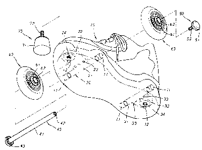
Fig. 1 is a diagram showing a prior art roller skate;
Fig. 2 is a perspective dialnam showing the exploded components of the present
invention;
Fig. 3 is a perspective diagram showing the assembly of the roller skate
thereof;
Fig. 4 is a rear side view of the roller skate of the present invention.
DETAILED DESCRIPT10N OF THE PREFERRED EIIiBODIhIENT
Referring to Fig. 2, the roller skate has a pair of shoe embodiments 10. Each
shoe embodiment 10 is equipped with a front securing seat 20, a rear securing
seat 3U, a
pair of wheel axles 40, a pair of locking screws 50, four roller wheels 60 and
a pair of
3

CA 02357352 2001-09-17
brake pieces 70.
The front securing seat 20 is embedded at the front end and the rear securing
seat 30 is embedded at the rear end of the shoe embodiment 10. The shoe
embodiment 10
is provided with a through hole 11 at each side thereof at the front end and
rear end
respectively. On the bottom of the shoe embodiment 10 are disposed a mounting
hole 12
at the front and the end heel portions thereof. The front securing seat 20 is
provided with
a tube 21 at the rear portion thereof which is positioned in alignment with a
pair of
through holes 11 of the shoe embodiment 10. The tube 21 is integrally
connected to an
extension plate 22 which is embedded at the front end of the shoe embodiment
and is
provided with an internally screwed locking hole 24 positioned in alignment
with the
mounting hole 12 of the shoe embodiment 10. There are a plurality of
engagement holes
23 defined on the extension plate 22 so as to make the fixing of the front
securing seat 20
to the shoe embodiment 10 in a more secure manner.
The rear securing seat 30 is provided with an axle tube 31 at the front
thereof
which is positioned in alignment with the through holes 11 of the shoe
embodiment 10.
An extension plate 32 integrally connected to the axle tube 31 is embedded in
the heel
portion of the shoe embodiment 10. There are a plurality of engagement holes
23 defined
right at the joint of the axle tube 31 and the extension plate 32 For better
retaining of the
rear securing seat 30 in the shoe embodiment 10. An internally threaded hole
34 defined
on the extension plate 32 is positioned in alignment with the mounting hole 12
of the
shoe embodiment 10.
The two wheel axles 4U are two rods 41 sized to match with the respective
width of the front portion and heel portion of the shoe embodiment 10. One end
of the
4

CA 02357352 2001-09-17
axle rods 41 is provided with a knob 43 and the other end is provided with an
internally
threaded hole 42 so as to permit a locking screw 50 which has a thread section
52 and a
driving knob 51.
Each roller wheel 60 has a hub flange 62 and a bearing 61 at each side thereof
The brake piece 70 is a plastic block 71 having a protruded bolt 72 at the top
thereof.
In assembly, a roller 60 is first engaged with the rod 41 of each wheel axle
40
with the roller 60 located in abutment with the knob 43 and then the rod 41 is
guided
through the through hole 11 and the tube 21 and the opposite through hole 11
of the shoe
embodiment 10, and then the other roller 60 is attached to the exposed end of
rod 41 and
locked in place by way of the knob-ended screw 50. In the same manner, the
other wheel
axle 41 is mounted to the shoe embodiment 10, as shown in Fig. 5.. The brake
pieces 70
are secured to the bottom of the shoe embodiment 10 with the bolts 72 of the
brake block
71 led through the mounting holes 12 and engaged with the internally threaded
locking
holes 24, 34 of the shoe embodiment 10 respectively.
In summary, the present invention has the following advantages in practical
operation:
l.The rollers 60 are easily and firmly mounted to the wheel axles 40 and
retained in place
by knob ends 43 and 51; such a structure can prevent the rollers from
disengagement of
the wheel axles and damage in use.
2. The wheel axles 40 are designed short enough to make the rollers 60 in as
close
abutment against the shoe embodiment as possible and the knob ends 43, 51 can
well
protect the ends of the wheel axles from damage, allowing the roller skate to
be durable
in use.
s

Representative Drawing
A single figure which represents the drawing illustrating the invention.
Administrative Status

2024-08-01:As part of the Next Generation Patents (NGP) transition, the Canadian Patents Database (CPD) now contains a more detailed Event History, which replicates the Event Log of our new back-office solution.

Please note that "Inactive:" events refers to events no longer in use in our new back-office solution.

For a clearer understanding of the status of the application/patent presented on this page, the site Disclaimer , as well as the definitions for Patent , Event History , Maintenance Fee  and Payment History  should be consulted.

Event History

Description Date
Inactive: Office letter 2007-02-27
Inactive: IPC from MCD 2006-03-12
Time Limit for Reversal Expired 2005-09-19
Application Not Reinstated by Deadline 2005-09-19
Inactive: Abandoned - No reply to s.30(2) Rules requisition 2004-12-03
Deemed Abandoned - Failure to Respond to Maintenance Fee Notice 2004-09-17
Inactive: S.30(2) Rules - Examiner requisition 2004-06-03
Application Published (Open to Public Inspection) 2003-03-17
Inactive: Cover page published 2003-03-16
Letter Sent 2002-01-14
Inactive: Correspondence - Transfer 2002-01-10
Inactive: Correspondence - Formalities 2001-11-16
Inactive: Single transfer 2001-11-16
Inactive: First IPC assigned 2001-11-16
Inactive: Courtesy letter - Evidence 2001-10-02
Inactive: Filing certificate - RFE (English) 2001-09-26
Filing Requirements Determined Compliant 2001-09-26
Application Received - Regular National 2001-09-26
Request for Examination Requirements Determined Compliant 2001-09-17
All Requirements for Examination Determined Compliant 2001-09-17

Abandonment History

Abandonment Date Reason Reinstatement Date
2004-09-17

Maintenance Fee

The last payment was received on 2003-06-30

Note : If the full payment has not been received on or before the date indicated, a further fee may be required which may be one of the following

  • the reinstatement fee;
  • the late payment fee; or
  • additional fee to reverse deemed expiry.

Please refer to the CIPO Patent Fees web page to see all current fee amounts.

Fee History

Fee Type Anniversary Year Due Date Paid Date
Request for examination - standard 2001-09-17
Application fee - standard 2001-09-17
Registration of a document 2001-11-16
MF (application, 2nd anniv.) - standard 02 2003-09-17 2003-06-30
Owners on Record

Note: Records showing the ownership history in alphabetical order.

Current Owners on Record
OCEAN WELL FOOTWEAR CO., LTD.
JONG-MING LEE
Past Owners on Record
HUNG-LUNG HUANG
Past Owners that do not appear in the "Owners on Record" listing will appear in other documentation within the application.
Documents

To view selected files, please enter reCAPTCHA code :


To view images, click a link in the Document Description column. To download the documents, select one or more checkboxes in the first column and then click the "Download Selected in PDF format (Zip Archive)" or the "Download Selected as Single PDF" button.

List of published and non-published patent-specific documents on the CPD .

If you have any difficulty accessing content, you can call the Client Service Centre at 1-866-997-1936 or send them an e-mail at CIPO Client Service Centre.


Document
Description 
Date
(yyyy-mm-dd) 
Number of pages   Size of Image (KB) 
Representative drawing 2002-03-11 1 15
Cover Page 2003-02-21 1 48
Drawings 2001-09-17 4 79
Description 2001-09-17 5 193
Claims 2001-09-17 2 68
Abstract 2001-09-17 1 28
Filing Certificate (English) 2001-09-26 1 175
Courtesy - Certificate of registration (related document(s)) 2002-01-14 1 113
Reminder of maintenance fee due 2003-05-21 1 107
Courtesy - Abandonment Letter (Maintenance Fee) 2004-11-15 1 176
Courtesy - Abandonment Letter (R30(2)) 2005-02-14 1 166
Correspondence 2001-09-27 1 24
Correspondence 2001-11-16 1 48
Correspondence 2007-02-27 1 23
Correspondence 2007-03-16 6 220