Note: Descriptions are shown in the official language in which they were submitted.
CA 02357473 2001-09-19
JJ-11 325CA
TITLE: FUEL TANK FIXING STRUCTURE OF SMALL-SIZE BOAT
FIELD OF THE INVENTION
The present invention relates to a fuel tank
fixing structure of a small-size boat, in particular, a
saddle-ride type small-size boat.
BACKGROUND OF THE INVENTION
As a conventional fuel tank fixing structure of
a small-size boat has been known a structure shown, for
example, in FIG. 8(a) in which a pair of tank supporting
portions 3, 3 are provided on the bottom portion of the
inner wall 2 of a hull 1, in which a fuel tank
(hereinafter simply referred to as a tank) 4 is mounted
on the tank supporting portions 3, 3, in which the bottom
portion of the tank 4 is sandwiched by the pair of tank
supporting portions 3, 3 to position the tank 4, and in
which the tank 4 is fixed to the hull by a belt 5, which
is fixed to one side of the hull and looped over the top
surface of the tank 4 to the other side of the hull (see
Japanese Unexamined Patent Publication No. 4- 201797).
Further, for example, as shown in FIG. 9, a
structure is also known in which a tank 6 is formed in a
shape adapted to the bottom portion of the inner wall 7
of a hull and is sandwiched, positioned and fixed by
inner wall side surfaces 8, 8 opposed to each other (see
Japanese Unexamined Patent Publication No. 5- 16882).
The above-mentioned conventional tank fixing
structure presents a problem that a tank is not always
positioned and fixed in a stable state, as described
below.
That is, usually, a fuel tank does not always
have a high dimensional accuracy. The fuel tank is
molded by blowing synthetic resin in many cases and in
particular, in the case where the fuel tank is made by
- 1 -
CA 02357473 2001-09-19
JJ-11 325CA
the blow-molding method, the dimensional accuracy
inevitably becomes low.
Under such conditions, for example, as shown in
FIG. 8, in the structure in which the pair of tank
supporting portions 3, 3 sandwich the tank 4 to position
the tank 4, as shown in FIG. 8(b), in the case where the
tank 4 is smaller than a predetermined size, a gap C is
produced between the smaller tank 4' and the supporting
portions 3, 3 and hence the tank 4' can not be positioned
and fixed in a stable state. On the contrary, as shown
in FIG. 8(c), in the case where the tank 4 is larger than
the predetermined size, the larger tank 4 " is pressed by
the supporting portions 3, 3 by forces F, F larger than
required to produce unnecessary stress in the thank 4 " .
Such a problem is similarly presented in the
structure shown in FIG. 9: in the case where the tank 6
is smaller than a predetermined size, a gap is produced
between the small tank and the inner wall surfaces 8, 8
and the tank can not be positioned and fixed in a stable
state; on the contrary, in the case where the tank 6 is
larger than the predetermined size, the larger tank 6 is
pressed by the inner wall side surfaces by forces larger
than required to generate an unnecessary stress in the
tank 6.
The object of the present invention is to solve
the problem described above and to provide a fuel tank
fixing structure of a small-size boat capable of
positioning a tank in a stable state and not producing
any unnecessary stress in the tank.
SUMMARY OF THE INVENTION
In order to accomplish the above object, a fuel
tank fixing structure of a small-size boat according to
the present invention is characterized in that a single
projecting or depressed portion for positioning, which is
- 2 -
CA 02357473 2001-09-19
JJ-11 325CA
tapered, is formed on the inner wall of the bottom
portion of a hull; in that a single projecting or
depressed portion for positioning, which is tapered, in
the same direction of the projecting or depressed portion
and is fitted on the projecting or depressed portion, is
formed on the bottom portion of a fuel tank mounted on
the bottom portion of the hull; and in that a space is
formed, in a plan view, between the peripheral wall of
the fuel tank and the inner wall of the hull.
In an aspect of the invention, a fuel tank
fixing structure of a small-size boat is characterized in
that, in the fuel tank fixing structure of a small-size
boat as claimed in claim 1, at least a part of both sides
of the projecting or depressed portion formed on the
bottom surface of the fuel tank is formed in a slanting
surface slanting nearly parallel to the slanting portion
of the inner wall of the bottom portion of the hull; and
in that the slanting surface is supported movably in the
direction along the slanting surface by a projecting
supporting portion formed on the inner wall of the bottom
portion of the hull.
In another aspect of the invention, a fuel tank
fixing structure of a small-size boat as described above
is characterized in that, in the fuel tank fixing
structure of a small-size boat as claimed in claim 1 or
claim 2, the fuel tank is molded by blowing synthetic
resin.
In yet another aspect of the invention, a fuel
tank fixing structure of a small-size boat is
characterized in that, in the fuel tank fixing structure
of a small-size boat as described above, the fuel tank is
fixed to the hull by an elastic belt looped from one side
of the hull to the other side of the hull over the top
surface of the fuel tank; in that a support portion for
supporting a fuel hose communicating with the fuel tank
- 3 -
CA 02357473 2001-09-19
JJ-11 325CA
is provided on the top surface of the fuel tank; and in
that the fuel hose is fixed to the fuel tank by the
support portion and the elastic belt.
BRIEF DESCRIPTION OF THE DRAWINGS
Preferred embodiments of the invention are
shown in the drawings, wherein:
FIG. 1 is a side view, with parts partially
omitted, to show one example of a small-size boat using
one preferred embodiment of a fuel tank fixing structure
in accordance with the present invention.
FIG. 2 is a plan view.
FIG. 3 is a cross-sectional view, with parts
partially omitted, taken on a line III-III in FIG. 1.
FIG. 4 is a cross-sectional view, with parts
partially omitted, taken on a line IV-IV in FIG. 1.
FIG. 5 is a schematic perspective view of the
portion of the bottom portion of the inner wall of a hull
where a fuel tank is mounted.
FIG. 6 is a bottom view of a fuel tank.
FIG. 7(a) and FIG. 7(b) are views to show
operations and are enlarged views of FIG. 3.
FIG. 8(a), FIG. 8(b) and FIG. 8(c) are views to
show a conventional technology.
FIG. 9 is a view to show another conventional
technology.
DETAILED DESCRIPTION OF THE PREFERRED EMBODIMENTS
Preferred embodiments of the present invention
will hereinafter be described with reference to the
accompanying drawings.
FIG. 1 is a side view, with parts partially
omitted, to show one example of a small-size boat using
one preferred embodiment of a fuel tank fixing structure
in accordance with the present invention. FIG. 2 is a
- 4 -
CA 02357473 2001-09-19
JJ-11 325CA
plan view. FIG. 3 is a cross-sectional view, with parts
partially omitted, taken on a line III-III in FIG. 1.
FIG. 4 is a cross-sectional view, with parts partially
omitted, taken on a line IV-IV in FIG. 1. FIG. 5 is a
schematic perspective view of the portion of the inner
wall bottom of a hull where a fuel tank is mounted.
Then, FIG. 6 is a bottom view of a fuel tank.
As shown in these figures (mainly in FIG. 1), a
small-size boat 10 of the present preferred embodiment is
a saddle-type small-size boat and a rider sits on a seat
12 on a hull 11 and can drive the boat by gripping a
steering handlebar 13 with a throttle lever 13a (see FIG.
2) .
The hull 11 has a floating structure in which a
lower hull panel 14 is bonded to an upper hull panel 15
to form a space 16 therein. In the space 16, an engine
is mounted on the lower hull panel 14 and a jet pump
as a propelling unit driven by the engine 20 is
provided at he rear portion of the lower hull panel 14.
20 The jet pump 30 has a flow passage 32 extending
from a water intake port 17 made in the bottom of the
boat to a jet nozzle 31 provided at the rear end of the
hull and an impeller (not shown) disposed in the flow
passage 32 and the shaft 33 of the impeller is connected
25 to the output shaft 21 of the engine 20. Accordingly,
when the impeller is rotated by the engine 20, water
taken from the water intake port 17 is jetted out from
the nozzle 31 whereby the hull 11 is propelled. The
number of revolution of the engine 20, that is,
30 propelling force produced by the jet pump 30 is operated
by turning the throttle lever 13a (see FIG. 2) of the
operating handlebar 13. The nozzle 31 is connected to
the operating handlebar 13 by a operating wire (not
shown) and is turned by the operation of the handlebar 13
to change the direction of the boat.
- 5 -
CA 02357473 2001-09-19
JJ-11 325CA
A fuel tank 40 for supplying fuel to the engine
20 is mounted forward of the engine 20 on the bottom
portion of the inner wall of the hull 11.
The lower hull panel 14, as shown in FIG. 3 and
FIG. 4, has a double hull structure including an outer
hull 14a and an inner hull 14b at least at the portion
where the fuel tank 40 is mounted and the fuel tank 40 is
mounted on the inner hull 14b, that is, on the bottom
portion of the inner wall of the hull 11. Here, the
space between the outer hull 14a and the inner hull 14b
is filled with a foaming material 14c to form a floating
body.
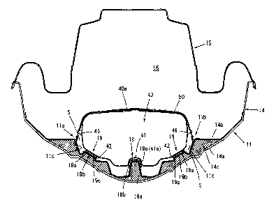
As shown in FIG. 3 to FIG. 5, the inner hull
14b is provided with a single projecting portion for
positioning 18 and four projecting supporting portions
19.
The projecting portion 18 includes a base
portion 18a integrally formed with the inner hull 14b and
a cap 18b made of an elastic material (for example,
rubber) and fixed to the base portion 18a so that it
covers the base portion 18a. Similarly, the supporting
portion 19 includes a base portion 19a integrally formed
with e inner hull 14b and a cap 19b made of an elastic
th
materia l (for example, rubber) and fixed to the base
portion 19a so that it covers the base portion 19a.
The outer peripheral surface of the projecting
portion for positioning 18 is formed in a tapered surface
(circul ar truncated cone) 18c.
On the other hand, as shown in FIG. 3 and FIG.
6, the bottom portion of the fuel tank 40 is formed in
a
single depressed portion for positioning 41, which is
fitted on the projecting portion for positioning 18 of
the hul l side.
The inner peripheral surface of the depressed
portion 41 is formed in a tapered surface (circular
- 6 -
CA 02357473 2001-09-19
JJ-11 325CA
truncated cone) 41c which is formed in the same direction
as the tapered surface 18c of the projecting portion for
positioning 18 of the hull side.
The fuel tank 40 is molded by blowing synthetic
resin (for example, polyethylene or the like) and
portions 42, 42 of both the sides of the depressed
portion for positioning 41 on the bottom surface are
formed in slanting surfaces 42 nearly parallel to the
slanting portion of the inner wall surface of the bottom
portion of the hull (in the present preferred embodiment,
top surface 19c of the cap 19b of the supporting portion
19) and these slanting surfaces 42, 42 are supported
movably in the direction along the slanting surface 42
(in the direction of an arrow (a) in FIG. 7) by the four
projecting supporting portion 19 formed on the inner wall
surface of the bottom portion of the hull.
The fuel tank 40 formed in the above manner, as
shown mainly in FIG. 3 and FIG. 4, is mounted on the
bottom portion of the hull so that the depressed portion
for positioning 41 is fitted on the projecting portion
for positioning 18 of the hull side and, in the mounting
state, the depressed portion for positioning 41 is fitted
on and positioned by the projecting portion for
positioning 18 of the hull side and the slanting surfaces
42, 42 of both sides are supported by the four supporting
portions 19 of the hull side.
Further, as shown in FIG. 3 to FIG. 5, the fuel
tank 40 is fixed to the hull 11 by an elastic belt (50,
50') looped from one side 11a of the hull 11 to the other
side 11b of the hull 11 along the top surface 40a of the
fuel tank 40. In FIG. 3, two elastic belts are used and
designated by symbols 50, 50' but the number of the belts
may be suitably selected. The number of the belts may be
one or may be three or more.
CA 02357473 2001-09-19
JJ-11 325CA
As shown in FIG. 4, a supporting portion 45 for
supporting a fuel supply hose 43 communicating with the
fuel tank 40 and a fuel return hose 44 are integrally
formed on the top surface 40a of the fuel tank 40 and the
fuel supply hose 43 and the fuel return hose 44 are fixed
to the fuel tank 40 by the supporting portion 45 and the
elastic belt 50.
A space S is formed, in the plan view, between
the peripheral wall 46 of the fuel tank 40 mounted in
this manner and the inner wall 11c of the hull 11 (see
FIG. 3 and FIG. 4).
The fuel tank fixing structure described above
can produce the following operations and effects.
(a) The single projecting portion for
positioning 18 with the taper 18c is formed on the bottom
portion of the inner wall of the hull 11, and the single
depressed portion for positioning 41, which is fitted on
the projecting portion 18 and has the taper 41c in the
same direction as the projecting portion 18, is formed on
the bottom of the fuel tank 40 mounted on the bottom
portion, and the space S is formed, in the plan view,
between the peripheral wall 46 of the fuel tank 40 and
the inner wall 11c of the hull 11. Therefore, when the
fuel tank 40 is mounted on the bottom portion of the
inner wall of the hull 11, the single depressed portion
for positioning 41 formed on the bottom portion of the
fuel tank 40 and having the taper in the same direction
as the projecting portion 18 is fitted on the single
projecting portion for positioning 18 with the taper,
which is formed on the bottom portion of the inner wall
of the hull 11, whereby the fuel tank 40 is positioned on
the bottom portion of the inner wall of the hull 11.
Since the tapers 18c, 41c are formed in the
same direction on the projecting portion 18 of the bottom
portion side of the hull 11 and on the depressed portion
_ g _
CA 02357473 2001-09-19
JJ-11 325CA
41 of the fuel tank 40 side and the space S is formed, in
the plan view, between the peripheral wall 46 of the fuel
tank 40 and the inner wall 11c of the hull 11, the
depressed portion 41 are fitted on the projecting portion
for positioning 18 by putting the tapered surface 18c
into contact with the tapered surface 41c.
Therefore, even if the fuel tank 40 does not
have a high dimensional accuracy, the tapered surface 41c
of the fuel tank 40 is fitted on the tapered surface 18c
of the projecting portion 18 of the hull 11 side, whereby
the depressed portion 41 of the fuel tank 40 side is
stably fitted on and positioned with respect to the
projecting portion 18 of the hull 11.
That is, even if the fuel tank 40 is a little
smaller than a predetermined size (shown by a solid line
40) , as shown by a single dot and dash line 40' in FIG.
7(a), or a little larger than the predetermined size, as
shown by a double dots and dash line 40" in FIG. 7 (b) ,
the fuel tank 40 is fitted with no play at the
positioning portion and has no unnecessary stress
generated therein. Further, since the space S is formed,
in the plan view, between the peripheral wall 46 of the
fuel tank 40 and the inner wall 11c of the hull 11, even
if the fuel tank 40 is a little larger than a
predetermined size, as shown by a double dots and dash
line 40" in FIG. 7(b), the outer peripheral wall of the
fuel tank 40 can be deflected toward the space S and
upward, so an unnecessary stress is not generated in the
fuel tank 40.
Further, even if the fuel tank 40 is mounted on
the hull 11 and then fuel is put into the fuel tank 40 to
expand the fuel tank 40, the tapered depressed portion 41
is fitted on the tapered projecting portion 18 and hence
the tank is kept in the stable positioning state and no
unnecessary stress is generated in the fuel tank 40.
- 9 -
CA 02357473 2001-09-19
JJ-11 325CA
As described above, according to the fuel tank
fixing structure of the present preferred embodiment, the
fuel tank 40 can be positioned and fixed in the stable
state and no unnecessary stress is generated in the fuel
tank 40. Further, even if the fuel tank 40 is mounted on
the hull 11 and then fuel in put into the tank 40 to
expand the fuel tank 40, the tank 40 is kept in the
stable positioning and fixing state and no unnecessary
stress is generated in the fuel tank 40.
(b) At least one part (42) of both sides of the
depressed portion 41 on the bottom surface of the fuel
tank 40 is formed in slanting surfaces 42, 42 slanting
nearly parallel to the slanting portion 19c of the inner
wall of the bottom portion of the hull and this slanting
surfaces 42, 42 are supported movably in the direction
along the slanting surface 42 ( in the direction shown by
an arrow (a) in FIG. 7) by the projecting supporting
portion 19 formed on the inner wall of the bottom portion
of the hull. For this reason, even if the fuel tank 40
is a little smaller or larger than a predetermined size,
as shown in FIG. 7(a), (b), the slanting surfaces 42, 42
are fitted on the supporting portion 19, which can
position and fix the fuel tank 40 in the more stable
state and further surely prevent the unnecessary stress
from being generated in the fuel tank 40.
Still further, even if the fuel tank 40 is
mounted on the hull 11 and fuel is put into the fuel tank
40 to expand the fuel tank 40, the slanting surfaces 42,
42 formed nearly parallel to the slanting portion 19c of
the inner wall of the bottom portion of the hull on both
sides of the depressed portion 41 on the bottom surface
of the fuel tank 40 are supported by the projecting
supporting portion 19 formed on the inner wall of the
bottom portion of the hull and can be moved in the
direction along the slanting surface 42 (in the direction
- 10 -
CA 02357473 2001-09-19
JJ-11 325CA
shown by an arrow (a) in FIG. 7). Therefore, this can
further surely prevent the unnecessary stress from being
generated in the fuel tank 40.
(c) Since the fuel tank 40 is molded by blowing
synthetic resin, the fuel tank 40 can be formed easily.
Although the fuel tank molded by blowing the
synthetic resin has a low dimensional accuracy, according
to this fuel tank fixing structure, even if the fuel tank
40 is molded by blowing the synthetic resin, the fuel
tank 40 can be positioned and fixed in the stable state
and no unnecessary stress is generated in the fuel tank
40. Further, even if the fuel tank 40 is mounted on the
hull 11 and then fuel is put into the fuel tank 40 to
expand the fuel tank 40, it is possible to keep the fuel
tank 40 in the stable positioning and fixing position and
to prevent an unnecessary stress from being generated in
the fuel tank 40.
That is, the fuel tank fixing structure like
the present preferred embodiment is particularly
effective in the case where the fuel tank 40 is molded by
blowing the synthetic resin.
(d) The fuel tank 40 is fixed to the hull 11 by
the elastic belts 50, 50' looped from the one side 11a of
the hull 11 to the other side 11b of the hull 11 over the
top surface 40a of the fuel tank 40. Therefore, even if
the fuel tank 40 is a little smaller or larger than the
predetermined size, it is possible to position and fix
the fuel tank 40 in the more stable state and to prevent
the unnecessary stress from being generated in the fuel
tank 40 by the operations and effects described in the
above (a) and (b) and the elastic action of the elastic
belts.
The supporting portion 45 for the fuel supply
hose 43 and the fuel return hose 44 both of which
communicate with the fuel tank 40 are provided on the top
- 11 -
CA 02357473 2001-09-19
JJ-11 325CA
surface of the fuel tank 40, and the fuel supply hose 43
and the fuel return hose 44 are fixed to the top surface
of the fuel tank 40 by the supporting portion 45 and the
elastic belt 50. Therefore, it is possible to position
and fix the fuel supply hose 43 and the fuel return hose
44 with the fuel tank 40 in the stable state.
According to the fuel tank fixing structure of
a small-size boat as described above, a single projecting
or depressed portion for positioning, which is tapered,
is formed on the inner wall of the bottom portion of a
hull, and a single projecting or depressed portion for
positioning, which is tapered in the same direction of
the projecting or depressed portion and is fitted on the
projecting or depressed portion, is formed on the bottom
portion of a fuel tank mounted on the bottom portion of
the hull, and a space is formed, in a plan view, between
the peripheral wall of the fuel tank and the inner wall
of the hull. Therefore, when the fuel tank is mounted on
the bottom portion of the inner wall of the hull, the
single projecting or depressed portion for positioning,
which is tapered in the same direction of the projecting
or depressed portion and is formed on the bottom portion
of the fuel tank is fitted on the single projecting or
depressed portion for positioning which is tapered and is
formed on the inner wall of the bottom portion of the
hull to position the fuel tank on the bottom portion of
the inner wall of the hull.
Since the projecting or depressed portion on
the bottom portion side of the hull and the depressed or
projecting portion of the fuel tank side are tapered in
the same direction and the space is formed, in the plan
view, between the peripheral wall of the fuel tank and
the inner wall of the hull, when the depressed (or
projecting) portion for positioning is fitted on the
projecting (or depressed) portion for positioning, the
- 12 -
CA 02357473 2001-09-19
JJ-11 325CA
tapered portions thereof are put into contact with each
other.
Therefore, even if the fuel tank does not have
a high dimensional accuracy, the tapered surface of the
depressed portion or the projecting portion of the fuel
tank side is fitted on the tapered surface of the
projecting portion or the depressed portion of the hull
side, whereby the depressed portion or the projecting
portion of the fuel tank side is positioned with respect
to the projecting portion or the depressed portion of the
hull side in a stable state.
That is, even if the fuel tank is a little
smaller or larger than a predetermined size, the fuel
tank is positioned with no play and no unnecessary stress
is generated in the fuel tank. Further, since the space
is formed, in the plan view, between the peripheral wall
of the fuel tank and the inner wall of the hull, even if
the fuel tank is a little larger than a predetermined
size, no unnecessary stress is generated in the fuel
tank.
Still further, even if the fuel thank is
mounted on the hull and then fuel is put into the fuel
tank to expand the fuel tank, the tapered depressed
portion is fitted on the tapered projecting portion and
hence the fuel tank is kept in the stable positioning
state and no unnecessary stress is generated in the fuel
tank.
As described above, the fuel tank can be
positioned and fixed in the stable state and no
unnecessary stress is generated in the fuel tank.
Further, even if the fuel thank is mounted on the hull
and then fuel is put into the fuel tank to expand the
fuel tank, it is possible to keep the fuel tank in the
stable positioning state and to prevent an unnecessary
stress from being generated in the fuel tank.
- 13 -
CA 02357473 2001-09-19
JJ-11 325CA
According to the fuel tank fixing structure of
a small-size boat described above, in the fuel tank
fixing structure of a small-size boat, at least a part of
both sides of the projecting or depressed portion formed
on the bottom surface of the fuel tank is formed in a
slanting surface slanting nearly parallel to the slanting
portion of the inner wall of the bottom portion of the
hull and the slanting surface is supported movably in the
direction along the slanting surface by a projecting
supporting portion formed on the inner wall of the bottom
portion of the hull. Therefore, even if the fuel tank is
a little smaller or larger than a predetermined size, it
is possible to position and fix the fuel tank in the more
stable state and to more surely prevent an unnecessary
stress from being generated in the fuel tank.
Further, even if the fuel thank is mounted on
the hull and then fuel is put into the fuel tank to
expand the fuel tank, the slanting surfaces, which are
formed on both sides of the depressed portion or the
projecting portion formed on the bottom surface of the
fuel tank nearly parallel to the slanting portions of the
inner wall of the bottom portion of the hull, are
supported by the projecting supporting portion formed on
the inner wall of the bottom portion of the hull and can
be moved in the direction along the slanting surfaces.
Therefore, it is possible to more surely prevent an
unnecessary stress from being generated in the fuel tank.
According to the fuel tank fixing structure of
a small-size boat as described above, the fuel tank is
molded by blowing synthetic resin and hence the fuel tank
can be formed easily.
As described above, when the fuel tank is
molded by blowing the synthetic resin, the fuel tank has
a low dimensional accuracy. However, according to this
fuel tank fixing structure, even if the fuel tank is
- 14 -
CA 02357473 2001-09-19
JJ-11 325CA
molded by blowing the synthetic resin, it is possible to
position and fix the fuel tank in the stable state and to
prevent an unnecessary stress from being generated in the
fuel tank. Further, even if the fuel thank is mounted on
the hull and then fuel is put into the fuel tank to
expand the fuel tank, it is possible to keep the fuel
tank in the stable positioning state and to prevent an
unnecessary stress from being generated in the fuel tank.
That is, the constitution of the preferred
embodiment is effective particularly in the case where
the fuel tank is molded by blowing synthetic resin.
According to the fuel tank fixing structure of
a small-size boat of a preferred embodiment, the fuel
tank is fixed to the hull by the elastic belt looped from
one side of the hull to the other side of the hull over
the top surface of the fuel tank. Therefore, even if the
fuel tank is a little smaller of larger than a
predetermined size, it is possible to position and fix
the fuel tank in the more stable state by the elastic
action of the elastic belt and to more surely prevent an
unnecessary stress from being generated in the fuel tank.
Further, since a support portion for supporting
a fuel hose communicating with the fuel tank is provided
on the top surface of the fuel tank and the fuel hose is
fixed to the fuel tank by the support portion and the
elastic belt, it is possible to position and fix the fuel
hose with the fuel tank in the stable stat.
While the preferred embodiment in accordance
with the present invention has been described up to this
point, it is not intended to limit the present invention
to the above preferred embodiment but the present
invention can be further modified within the spirit and
scope of the present invention.
- 15 -
CA 02357473 2001-09-19
JJ-11 325CA
For example, although the projecting portion
for positioning is formed on the bottom portion of the
inner wall of the hull and the depressed portion for
positioning is formed on the bottom portion of the fuel
tank in the above preferred embodiment, the depressed
portion for positioning may be formed on the bottom
portion of the inner wall of the hull and the projecting
portion for positioning may be formed on the bottom
portion of the fuel tank.
Although various preferred embodiments of the
present invention have been described herein in detail,
it will be appreciated by those skilled in the art, that
variations may be made thereto without departing from the
spirit of the invention or the scope of the appended
claims.
- 16 -