Language selection

Search

Patent 2357903 Summary

Third-party information liability

Some of the information on this Web page has been provided by external sources. The Government of Canada is not responsible for the accuracy, reliability or currency of the information supplied by external sources. Users wishing to rely upon this information should consult directly with the source of the information. Content provided by external sources is not subject to official languages, privacy and accessibility requirements.

Claims and Abstract availability

Any discrepancies in the text and image of the Claims and Abstract are due to differing posting times. Text of the Claims and Abstract are posted:

  • At the time the application is open to public inspection;
  • At the time of issue of the patent (grant).
(12) Patent Application: (11) CA 2357903
(54) English Title: LOG SPLITTING APPARATUS AND METHOD OF USE OF THE SAME
(54) French Title: MACHINE A FENDRE LE BOIS ET METHODE D'UTILISATION
Status: Deemed Abandoned and Beyond the Period of Reinstatement - Pending Response to Notice of Disregarded Communication
Bibliographic Data
(51) International Patent Classification (IPC):
  • B27L 07/04 (2006.01)
  • B27L 07/06 (2006.01)
(72) Inventors :
  • ELLISON, CHARLES ROBERT (Canada)
(73) Owners :
  • CHARLES ROBERT ELLISON
(71) Applicants :
  • CHARLES ROBERT ELLISON (Canada)
(74) Agent: THOMPSON LAMBERT LLP
(74) Associate agent:
(45) Issued:
(22) Filed Date: 2001-09-26
(41) Open to Public Inspection: 2003-03-26
Availability of licence: N/A
Dedicated to the Public: N/A
(25) Language of filing: English

Patent Cooperation Treaty (PCT): No

(30) Application Priority Data: None

Abstracts

English Abstract


A method and an apparatus for splitting logs which
includes a combination of an impact wrench and a conical screw-
form wedge. A first step involves providing an impact wrench
and a conical screw-form wedge. A second step involves
coupling the conical screw-form wedge to the output coupling
of the impact wrench. A third step involves placing the apex
of the conical screw-form wedge against a log and activating
the rotary and reciprocating movement of the impact wrench.
The combined rotary and reciprocating movement of the impact
wrench drives the conical screw-form wedge into the log. The
described combination is a compact, portable and comparatively
inexpensive log splitting apparatus.


Claims

Note: Claims are shown in the official language in which they were submitted.

6
THE EMBODIMENTS OF THE INVENTION IN WHICH AN EXCLUSIVE PROPERTY
OR PRIVILEGE IS CLAIMED ARE DEFINED AS FOLLOWS:
1. An apparatus for splitting logs comprising, in combination:
an impact wrench with an output coupling that provides
both rotary and reciprocating movement; and
a conical screw-form wedge coupled to the output coupling
of the impact wrench.

2. A method of splitting logs, comprising the steps of:
firstly, providing an impact wrench with an output
coupling that provides both rotary and reciprocating movement,
and a conical screw-form wedge having an apex;
secondly, coupling the conical screw-form wedge to the
output coupling of the impact wrench;
thirdly, placing the apex of the conical screw-form wedge
against a log and activating the rotary and reciprocating
movement of the impact wrench, whereby the combined rotary and
reciprocating movement drives the conical screw-form wedge into
the log.

Description

Note: Descriptions are shown in the official language in which they were submitted.


CA 02357903 2001-09-26
TITLE OF THE INVENTIONe
Log Splitting Apparatus And Method Of Use Of The Same
FIELD OF THE INVENTION
The present invention relates to a log splitting apparatus
and, in particular, a log splitting apparatus that uses a
conical screw-form wedge.
BACKGROUND OF THE INVENTION
Log splitting apparatus that use conical screw-form wedges
are disclosed in United States Patents 4,091,851 (Ober_ 1978);
4,245,683 (Cedergren 1981) and 4,347,881 (Wickham et a1 1982).
The Ober reference discloses a log splitting apparatus driven
by an internal combustion engine of about 5 to 8 horsepower
capacity and having a maximum output speed of about 3500 to
3600 revolutions per minute. A speed reduction unit is used
to reduce the revolutions per minute down between 60 to 70
revolution per minute, which is viewed by Ober as being the
preferred operating range for splitting logs with a conical
screw-form wedge. The Cedergren reference dlsClOSes a
protective guard which mounts to a work table to protect a
workman from injury when using a conical screw-form wedge in
a shop environment. The log splitting machine is not
described. The Wickham reference discloses a log splitting
apparatus driven off of the power take off (PTO) of a 1=ractor.
The reference includes features to improve the manner in which
logs are fed onto and off of the conical screw-form wedge and
features to protect the PTO shaft from fracturing due to
induced bending stresses.
The above described apparatus are suitable for persons
splitting large volumes of logs. Such apparatus are not
suitable for use by persons who wish to camp overnight or
picnic during an afternoon outing. Persons who camp or picnic
generally have limited storage space to transport a log

CA 02357903 2001-09-26
2
splitting apparatus and only split a few logs.
SUN~2ARY OF THE INVENTION
What is required is a hand held portable log spl~_tting
apparatus.
According to a first aspect of the present invention there
is provided an apparatus for splitting logs which includes a
combination of an impact wrench and a conical screw-form wedge.
The impact wrench has an output coupling that provides both
rotary and reciprocating movement. The conical screw-form
wedge is coupled to the output coupling of the impact wrench.
According to another aspect of the present invention there
is provided a method of splitting logs. A first step involves
providing an impact wrench and a conical screw-form wedge, as
described above. A second step involves coupling the conical
screw-form wedge to the output coupling of the impact wrench.
A third step involves placing the apex of the conical screw-
form wedge against a log and activating the rotary and
reciprocating movement of the impact wrench. The combined
rotary and reciprocating movement of the impact wrench drives
the conical screw-form wedge into the log.
The prior art devices such as disclosed in the Ober
reference and the Wickham et al reference rely upon generating
sufficient torque output to drive the conical screw-form wedge
into a log. When one attempts to provide a miniature portable
log splitting apparatus follow the same principles as are found
in the Ober reference and the Wickham et al reference, the
results are not satisfactory as the torque generated is
inadequate. In contrast, beneficial results may be obtained
through the combination apparatus and method described above.
The additional reciprocating movement of the impact wrench,
enables the conical screw-form wedge to operate effectively
with decreased torque.

CA 02357903 2001-09-26
3
BRIEF DESCRIPTION OF THE DRAWINGS
These and other .features of the invention will become more
apparent from the following description in which reference is
made to the appended drawings, the drawings are for the purpose
of illustration only and are not intended to in any way limit
the scope of the invention to the particular embodiment or
embodiments shown, wherein:
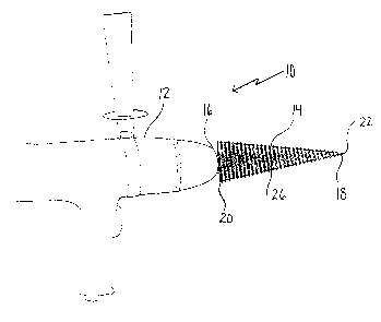
FIGURE 1 is a side elevation view of a log splitting
apparatus constructed in accordance with the teachings of the
present invention, being used in accordance with the teachings
of the preferred method.
FIGURE 2 is an exploded side elevation view of the log
splitting apparatus illustrated in FIGURE 1.
FIGURE 3 is a side elevation view of a conical screw-form
wedge having a first alternative form of coupling for coupling
to an output coupling of an impact wrench.
FIGURE 4 is a side elevation view of a conical screw-form
wedge having a second alternative form of coupling for coupling
to an output coupling of an impact wrench.
DETAILED DESCRIPTION OF THE PREFERRED EMBODIMENT
The preferred embodiment, a log splitting apparatus
generally identified by reference numeral 10, will now be
described with reference to FIGURES 1 through 4.
Structure and Relationship of Parts:
Referring to FIGURE 1 there is provided an apparatus for
splitting logs 10 which includes, in combination, an impact
wrench 12 and a conical screw-form wedge 14. Referring to
FIGURE 2, impact wrench 12 has an output coupling 16 that
provides both rotary and reciprocating movement. Conical screw-
form wedge 14 is coupled to output coupling 16 of impact wrench
12. Conical screw-form wedge 14 has a first end 18 and a
second end 20. A po~_nted apex 22 is positioned at first end
18 and a coupling 24 is positioned at second end 20. Conical
screw-form wedge 14 has a body 26 that increases in diameter
from apex 22 at first end 18 toward second end 20. Coupling

CA 02357903 2001-09-26
4
24 at second end 20 is adapted to be coupled to output coupling
16 of impact wrench 12. In the illustrated embodiment, coupling
16 is square shaped, however alternative configurations of
couplings 16 can also be used depending on output coupling 16
of impact wrench 12 as will hereinafter be discussed.
Operation:
The use and operation of apparatus for splitting logs will now
be described with reference to FIGURES 1 through 4.
Referring to FIGURE 1, when it is necessary to split logs,
impact wrench 12 and a conical screw-form wedge 14 as described
above, can be used. Conical screw-form wedge 14 is coupled to
output coupling 16 of impact wrench 12. Impact wrench 1.2 can
be either an electric, pneumatic or hydraulic impact wrench 12.
Apex 22 of conical screw-form wedge 14 is then placed against
a log. Rotary and reciprocating movement of impact wrench 12
is activated so that the combined rotary and reciprocating
movement drives conical screw-form wedge 14 into log to split
log apart.
Because apparatus for splitting logs 10 is relatively
small and light enough to be portable, it can be used in
situations where large log splitting machines are not
appropriate such as picnic sites, overnight campsite, or site
that are generally inaccessible to larger log splitting
devices. Furthermore, apparatus 10 does not require a
substantial amount of strength to operate therefore even
individuals without substantial strength can operate apparatus
for log splitting 10.
Variations:
In order to practise the teaching of the present
invention, conical screw-form wedges will have to be
manufactured that are capable of being coupled to the output
coupling of an impact wrench. Three of the more popular forms
of coupling are shown. Referring to FIGURE 1, coupling on
conical screw-form wedge 14 can have a square shaped coupling

CA 02357903 2001-09-26
24. Referring to FIGURE 3, as an alternative, conical screw-
form wedge 14 can have a star shaped coupling 28. Referring to
FIGURE 4, as another example, conical screw-form wedge 14 could
have a hexagon shaped coupling 30.
5
In this patent document, the word "comprising" is used in
its non-limiting sense to mean that items following the word
are included, but items not specifically mentioned are not
excluded. A reference to an element by the indefinite article
"a" does not exclude the possibility that more than one of the
element is present, unless the context clearly requires that
there be one and only one of the elements.
It will be apparent to one skilled in the art that
modifications may be made to the illustrated embodiment without
departing from the spirit and scope of the invention as
hereinafter defined in the Claims.

Representative Drawing
A single figure which represents the drawing illustrating the invention.
Administrative Status

2024-08-01:As part of the Next Generation Patents (NGP) transition, the Canadian Patents Database (CPD) now contains a more detailed Event History, which replicates the Event Log of our new back-office solution.

Please note that "Inactive:" events refers to events no longer in use in our new back-office solution.

For a clearer understanding of the status of the application/patent presented on this page, the site Disclaimer , as well as the definitions for Patent , Event History , Maintenance Fee  and Payment History  should be consulted.

Event History

Description Date
Application Not Reinstated by Deadline 2007-09-26
Time Limit for Reversal Expired 2007-09-26
Deemed Abandoned - Failure to Respond to Maintenance Fee Notice 2006-09-26
Inactive: Abandon-RFE+Late fee unpaid-Correspondence sent 2006-09-26
Application Published (Open to Public Inspection) 2003-03-26
Inactive: Cover page published 2003-03-25
Inactive: IPC assigned 2001-11-20
Inactive: First IPC assigned 2001-11-20
Inactive: Filing certificate - No RFE (English) 2001-10-12
Application Received - Regular National 2001-10-11

Abandonment History

Abandonment Date Reason Reinstatement Date
2006-09-26

Maintenance Fee

The last payment was received on 2005-09-07

Note : If the full payment has not been received on or before the date indicated, a further fee may be required which may be one of the following

  • the reinstatement fee;
  • the late payment fee; or
  • additional fee to reverse deemed expiry.

Patent fees are adjusted on the 1st of January every year. The amounts above are the current amounts if received by December 31 of the current year.
Please refer to the CIPO Patent Fees web page to see all current fee amounts.

Fee History

Fee Type Anniversary Year Due Date Paid Date
Application fee - small 2001-09-26
MF (application, 2nd anniv.) - small 02 2003-09-26 2003-09-08
MF (application, 3rd anniv.) - small 03 2004-09-27 2004-08-24
MF (application, 4th anniv.) - small 04 2005-09-26 2005-09-07
Owners on Record

Note: Records showing the ownership history in alphabetical order.

Current Owners on Record
CHARLES ROBERT ELLISON
Past Owners on Record
None
Past Owners that do not appear in the "Owners on Record" listing will appear in other documentation within the application.
Documents

To view selected files, please enter reCAPTCHA code :


To view images, click a link in the Document Description column. To download the documents, select one or more checkboxes in the first column and then click the "Download Selected in PDF format (Zip Archive)" or the "Download Selected as Single PDF" button.

List of published and non-published patent-specific documents on the CPD .

If you have any difficulty accessing content, you can call the Client Service Centre at 1-866-997-1936 or send them an e-mail at CIPO Client Service Centre.


Document
Description 
Date
(yyyy-mm-dd) 
Number of pages   Size of Image (KB) 
Representative drawing 2002-03-12 1 8
Description 2001-09-25 5 237
Claims 2001-09-25 2 32
Drawings 2001-09-25 3 63
Abstract 2001-09-25 1 22
Filing Certificate (English) 2001-10-11 1 175
Reminder of maintenance fee due 2003-05-26 1 107
Reminder - Request for Examination 2006-05-28 1 116
Courtesy - Abandonment Letter (Request for Examination) 2006-12-04 1 167
Courtesy - Abandonment Letter (Maintenance Fee) 2006-11-20 1 175
Fees 2003-09-07 1 27
Fees 2004-08-23 1 29
Fees 2005-09-06 1 27