Language selection

Search

Patent 2357904 Summary

Third-party information liability

Some of the information on this Web page has been provided by external sources. The Government of Canada is not responsible for the accuracy, reliability or currency of the information supplied by external sources. Users wishing to rely upon this information should consult directly with the source of the information. Content provided by external sources is not subject to official languages, privacy and accessibility requirements.

Claims and Abstract availability

Any discrepancies in the text and image of the Claims and Abstract are due to differing posting times. Text of the Claims and Abstract are posted:

  • At the time the application is open to public inspection;
  • At the time of issue of the patent (grant).
(12) Patent: (11) CA 2357904
(54) English Title: SHOE WITH REPLACEABLE VAMP AND INSOLE
(54) French Title: CHAUSSURE A EMPEIGNE ET SEMELLE INTERIEURE REMPLACABLE
Status: Expired and beyond the Period of Reversal
Bibliographic Data
(51) International Patent Classification (IPC):
  • A43B 9/00 (2006.01)
  • A43B 3/10 (2006.01)
(72) Inventors :
  • TSAI, MAO-CHENG (Taiwan, Province of China)
(73) Owners :
  • MAO-CHENG TSAI
(71) Applicants :
  • MAO-CHENG TSAI (Taiwan, Province of China)
(74) Agent: KIRBY EADES GALE BAKER
(74) Associate agent:
(45) Issued: 2004-06-22
(22) Filed Date: 2001-09-26
(41) Open to Public Inspection: 2003-03-26
Examination requested: 2001-09-26
Availability of licence: N/A
Dedicated to the Public: N/A
(25) Language of filing: English

Patent Cooperation Treaty (PCT): No

(30) Application Priority Data: None

Abstracts

English Abstract


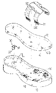
A shoe with replaceable vamp and insole consists of an outsole,
an insole, a vamp and a plurality of anchor blocks. The outsole
and insole have respectively anchor bores and anchor struts to
attain replacement function. The outsole has housing chambers for
holding the anchor blocks and a storing chamber for storing a
dismantle tool. The anchor block has a wedge trough to engage
with a latch section of the vamp to allow the vamp be replaced as
desired.


Claims

Note: Claims are shown in the official language in which they were submitted.

What is claimed is:
1. A shoe with replaceable vamp and insole, comprising:
an outsole having a plurality of anchor bores, a plurality of
housing chambers and a storing chamber formed on an upper
surface thereof, each of the housing chambers holding an
anchor block, the storing chamber holding a dismantle tool;
an insole fastened to the outsole having a plurality of anchor
struts located on a lower surface thereof mating the anchor bores
of the outsole; and
a vamp fastened to the outsole having latch sections located at
ends thereof, each latch section having an extensible section.
2. The shoe with replaceable vamp and insole of claim 1, wherein
the anchor block has a flange to engage with the outsole, a
wedge trough and a push pin, the wedge trough having a retain
edge formed therein.
3. The shoe with replaceable vamp and insole of claim 1, wherein
the dismantle tool has an upper pry section and lower pry
section.
4. The shoe with replaceable vamp and insole of claim 1, wherein
the anchor strut and the anchor bore have respectively an annular
indented groove and an annular jutting ring formed thereon.
5. The shoe with replaceable vamp and insole of claim 1, wherein
the housing chamber contains an anchor block to engage with
8

the latch section of the vamp, the anchor block having a flange, a
wedge trough and a push pin, the wedge trough having an
elastic retain section, the elastic retain section having a
plurality of first latch teeth formed on the exterior surface
thereof to match and engage with a plurality of second latch
teeth formed on the latch section.
6. The shoe with replaceable vamp and insole of claim 1, wherein
the housing chamber contains an anchor block to engage with
the latch section of the vamp, the anchor block having a flange
and a wedge trough, the wedge trough having an elastic retain
section, the elastic retain section and the latch section having
respectively a plurality of first latch teeth and second latch teeth
formed thereon to match and engage with each other.
9

Description

Note: Descriptions are shown in the official language in which they were submitted.


CA 02357904 2001-09-26
SHOE WITH REPLACEABLE VAMP AND INSOLE
FIELD OF THE INVENTION
The present invention relates to an improved shoe and
particularly a shoe that has a replaceable vamp and insole.
BACKGROUND OF THE INVENTION
A conventional shoe, such as the one shown in FIG. l,
generally has a vamp made by stitching, then the vamp and insole
are glued and bonded together, then the vamp and the outsole are
glued and compressed to complete the fabrication of the shoe. The
shoe made by gluing and compressing lacks strong bonding power
and tensile resistance. The vamp and insole and outsole are prone to
separate and fall apart.
Moreover, the shoe with the vamp and insole and outsole fixedly
bonded by gluing cannot be replaced by individual parts. They have
limited practicality and interchange capability.
SUMMARY OF THE INVENTION
In view of aforesaid disadvantages, it is therefore a primary
object of the invention to provide a shoe that has anchor struts and
anchor bores formed respectively on the lower surface of the insole
and upper surface of the outsole to allow the insole and outsole
assembling and dismantling freely as desired.

CA 02357904 2001-09-26
Another object of the invention is to provide a plurality of
housing chambers on the upper surface of the outsole for holding
anchor blocks to facilitate assembly and disassembly of the vamp.
A further object of the invention is to provide various types of
anchor blocks to fasten the vamp.
To attain the foregoing object, the shoe according to the invention
mainly includes an outsole, an insole, a vamp and a plurality of
anchor blocks. The outsole and insole are fastened through anchor
bores and anchor struts to allow the insole be detached and replaced.
The outsole has a plurality of housing chambers and a storing
chamber for holding respectively anchor blocks and a dismantle
tool. The anchor block has a wedge trough to engage with the
latch section of the vamp to allow the vamp be removed and
replaced whenever desired.
The foregoing, as well as additional objects, features and
advantages of the invention will be more readily apparent from the
following detailed description, which proceeds with reference to the
accompanying drawings.
BRIEF DESCRIPTION OF THE DRAWINGS
FIG. 1 is a perspective view of a conventional shoe.
FIG. 2 is an exploded view of the invention.
FIG. 3 is a perspective view of an insole of the invention.
FIG. 4 is a perspective view of the invention..
2

CA 02357904 2001-09-26
FIG. 5 is a fragmentary cross section of an anchor strut engaging
with an anchor bore.
FIG. 6 is an exploded view of an anchor block.
FIG. 7 is a cross section taken along line 7-7 in FIG. 4.
FIG. 7A is a cross section according to FIG. 7, showing the vamp
under removing.
FIG. 8 is an exploded view of another embodiment of the anchor
block.
FIG. 9 is an exploded view of yet another embodiment of the
anchor block.
DESCRIPTION OF THE PREFERRED EMBODIMENTS
Referring to FIGS. 2 through 9, the shoe according to the
invention mainly consists of the following elements:
an outsole 10 which has a plurality of anchor bores 11, a
plurality of housing chambers 12 and a storing chamber 13
formed on the upper surface. Each anchor bore 11 has an
annular jutting ring 110 (as shown in FIG. 5). The housing
chamber 12 may hold and engage with an anchor block 20, The
storing chamber 13 is to house a dismantle tool 30 which is
formed substantially in an inverse Y-shape with an upper pry
section 3 l and a lower pry section 32;
an insole 40 mounted to the upper surface of the outsole 10
3

CA 02357904 2001-09-26
includes a plurality of anchor struts 41 located on the lower
surface mating the anchor bores 11 of the outsole 10. Each anchor
strut 41 has an annular indented groove 410 mating and
engageable with the annular jutting ring 110 of the anchor bore
11 (as shown in FIG. 5);
a vamp 50 fastenable to the outsole 10 has latch sections 51
located at the ends thereof. Each latch section 51 has an
extensible section 510; and
a plurality of anchor blocks 20 each leas a flange 21 to engage
with the outsole 10 and to conceal securely in the housing
chamber 12. The anchor block 20 further has a wedge trough 22
and a push pin 23. The wedge trough 22 has a retain edge 220
(as shown in FIG. 7).
When to assemble the invention, insert the latch section S 1 of
the vamp 50 into the wedge trough 22 of the anchor block 22 with
the extensible section 510 of the latch section 51 latching to the
retain edge 220 (as shown in FIG. 7) to allow the vamp 50
fastening securely to the peripheral edge of the outsole 10.
Then dispose the anchor blocks 20 into the housing chambers 12
and the dismantle tool 30 into the storing chamber 13. 'Then
wedge the anchor struts 41 of the insole 40 into the anchor bores 11
of the outsole 10 with the annular indented groove 410 engaging
with the annular jutting ring 110 (as shown in FIG. 5) to allow the
insole 40 fastening to the outsole 10.
4

CA 02357904 2001-09-26
When to disassemble, pull the insole 40 slightly upwards to
detach the anchor struts 41 from the anchor bores 11 for separating
the insole 40 from the outsole 10. Then replace the insole 40 of
different materials or styles or colors as desired.
When the anchor block 20 is held in the housing chamber 12,
there is extra space in the housing chamber 12 to receive users'
finger for depressing the push pin 23 towards the latch section ~ 1 to
separate the extensible section 510 from the retain edge 220, then
the latch section 51 may be removed from the wedge trough 22 (as
shown in FIG. 7A), and the vamp 50 may be separated from the
outsole 10 for replacing the vamp SO of different materials or styles
or colors.
By means of the construction and method set forth above, the
vamp and insole may be changed and replaced freely as desired.
FIG. 8 shows another embodiment of the invention with a
different anchor block 20' and latch section 51' from the previous
embodiment. The anchor block 20' also has a flange 21' to engage
with the outsole (not shown in the drawing) and conceal securely in
the housing chamber (not shown in the drawing) of the outsole.
The anchor block 20' also has a wedge trough 22' and push pin 23'
and an elastic retain section 220'. The elastic retain section 220' has
a plurality of first latch teeth 24' formed on the exterior surface to
match and engage with a plurality of second latch teeth 510' formed
on the inner surface of the latch section 51' . When to disengage the
latch section 51' from the elastic retain section 220', depress the
5

CA 02357904 2001-09-26
push pin 23' against the elastic retain section 220', the latch section
51' may be disengaged from the elastic retain section 220' for
moving the vamp 50 away.
The dismantle tool 30 may be stored in the storing chamber (not
shown in the drawing) of the outsole (also not shown in the
drawing). The upper pry section 31 may be wedged between the
elastic retain section 220' and the latch section 51' to depress the
elastic retain section 220' inwards, the latch section 51' may be
disengaged from the elastic retain section 220' easily.
FIG. 9 shows yet another embodiment of the invention. The
anchor block 20" also has a flange 21" to engage with the outsole
(not shown in the drawing) and conceal securely in the housing
chamber (not shown in the drawing) of the outsole. The anchor
block 20" also has a wedge trough 22" and an elastic retain section
220". The elastic retain section 220" has a plurality of first latch
teeth 24" formed on the exterior surface to match and engage with a
plurality of second latch teeth 510" formed on the inner surface of
the latch section 51". When to disengage the latch section 51" from
the elastic retain section 220', wedge the lower pry section 32 of the
dismantle tool 30 between the elastic retain section 220" and the
latch section 51" and depress the elastic retain section 220" inwards,
the latch section 51" may be disengaged from the elastic retain
section 220" easily.
By means of any of the anchor blocks 20, 20' and 20" set forth
above, the vamp 50, 50' and 50" may be changed and replaced as
6

desired.
7

Representative Drawing
A single figure which represents the drawing illustrating the invention.
Administrative Status

2024-08-01:As part of the Next Generation Patents (NGP) transition, the Canadian Patents Database (CPD) now contains a more detailed Event History, which replicates the Event Log of our new back-office solution.

Please note that "Inactive:" events refers to events no longer in use in our new back-office solution.

For a clearer understanding of the status of the application/patent presented on this page, the site Disclaimer , as well as the definitions for Patent , Event History , Maintenance Fee  and Payment History  should be consulted.

Event History

Description Date
Time Limit for Reversal Expired 2006-09-26
Inactive: IPC from MCD 2006-03-12
Letter Sent 2005-09-26
Grant by Issuance 2004-06-22
Inactive: Cover page published 2004-06-21
Inactive: Final fee received 2004-04-07
Pre-grant 2004-04-07
Notice of Allowance is Issued 2003-10-20
Letter Sent 2003-10-20
Inactive: Approved for allowance (AFA) 2003-09-29
Application Published (Open to Public Inspection) 2003-03-26
Inactive: Cover page published 2003-03-25
Inactive: First IPC assigned 2001-11-29
Inactive: Filing certificate - RFE (English) 2001-10-12
Filing Requirements Determined Compliant 2001-10-12
Application Received - Regular National 2001-10-11
Request for Examination Requirements Determined Compliant 2001-09-26
All Requirements for Examination Determined Compliant 2001-09-26

Abandonment History

There is no abandonment history.

Maintenance Fee

The last payment was received on 2003-09-10

Note : If the full payment has not been received on or before the date indicated, a further fee may be required which may be one of the following

  • the reinstatement fee;
  • the late payment fee; or
  • additional fee to reverse deemed expiry.

Please refer to the CIPO Patent Fees web page to see all current fee amounts.

Fee History

Fee Type Anniversary Year Due Date Paid Date
Request for examination - small 2001-09-26
Application fee - small 2001-09-26
MF (application, 2nd anniv.) - small 02 2003-09-26 2003-09-10
Final fee - small 2004-04-07
MF (patent, 3rd anniv.) - small 2004-09-27 2004-09-02
Owners on Record

Note: Records showing the ownership history in alphabetical order.

Current Owners on Record
MAO-CHENG TSAI
Past Owners on Record
None
Past Owners that do not appear in the "Owners on Record" listing will appear in other documentation within the application.
Documents

To view selected files, please enter reCAPTCHA code :


To view images, click a link in the Document Description column. To download the documents, select one or more checkboxes in the first column and then click the "Download Selected in PDF format (Zip Archive)" or the "Download Selected as Single PDF" button.

List of published and non-published patent-specific documents on the CPD .

If you have any difficulty accessing content, you can call the Client Service Centre at 1-866-997-1936 or send them an e-mail at CIPO Client Service Centre.


Document
Description 
Date
(yyyy-mm-dd) 
Number of pages   Size of Image (KB) 
Representative drawing 2002-03-14 1 11
Cover Page 2003-03-03 1 35
Abstract 2001-09-26 1 15
Description 2001-09-26 7 257
Drawings 2001-09-26 10 152
Claims 2001-09-26 2 66
Cover Page 2004-05-27 1 35
Filing Certificate (English) 2001-10-12 1 175
Reminder of maintenance fee due 2003-05-27 1 107
Commissioner's Notice - Application Found Allowable 2003-10-20 1 159
Maintenance Fee Notice 2005-11-21 1 173
Correspondence 2004-04-07 1 32