Note: Descriptions are shown in the official language in which they were submitted.
CA 02357983 2005-11-28
PARTIALLY DEMINERALIZED CORTICAL
BONE CONSTRUCTS
FIELD OF INVENTION
The present invention is generally directed toward a surgical bone product and
more
specifically is a shaped partially demineralized allograft bone device or
construct with a mineralized
central section.
BACKGROUND OF THE INVENTION
The use of substitute bone tissue dates back around 1800. Since that time
research
efforts have been undertaken toward the use of materials which are close to
bone in composition to
facilitate integration of bone grafts. Development have taken place in the use
of grafts of a mineral
nature such as corals, hydroxyapatites, ceramics or synthetic materials such
as biodegradable polymer
materials. Surgical implants should be designed to be biocompatible in order
to successfully perform
their intended function. Biocompatibility may be defmed as the characteristic
of an implant acting
in such a way as to allow its therapeutic function to be manifested without
secondary adverse affects
such as toxicity, foreign body reaction or cellular disruption.
Human allograft tissue is widely used in orthopaedic, neuro-, maxillofacial,
podiatric
and dental surgery. The tissue is valuable because it is strong, biointegrates
in time with the recipient
patient's tissue and can be shaped either by the surgeon to fit the specific
surgical defect or shaped
commercially in a manufacturing environment. Contrasted to most synthetic
absorbable or
nonabsorbable polymers or metals, allograft tissue is bioinert and integrates
with the surrounding
tissues. Allograft bone occurs in two basic forms; cancellous and cortical.
Cortical bone is a higlily
dense structure comprised of triple helix strands of collagen fiber,
reinforced with hydroxyapatite.
The cortical bone is a compound structure and is the load bearing component of
long bones in the
human body. The hydroxyapatite component is responsible for the high
compressive strength of the
P,one while the collagen fiber component contributes in part to torsional and
tensile strength.
Many devices of varying shapes and forms can be fabricated from allograft
cortical
tissue by machining and surgical implants such as pins, rods, screws, anchors,
plates, intervertebral
CA 02357983 2001-10-02
2
spacers and the like have been made and used successfully in human surgery.
These engineered
shapes are used by the surgeon in surgery to restore defects in bone to the
bone's original anatomical
shape. This treatment is well known in the art and is commercially available
as demineralized bone.
Allograft bone is a logical substitute for autologous bone. It is readily
available and
precludes the surgical complications and patient morbidityassociated with
obtaining autologous bone
as noted above. Allograft bone is essentially a collagen fiber reinforced
hydroxyapatite matrix
containing active bone morphogenic proteins (BMP) and can be provided in a
sterile form The
demineralized form of allografft bone is naturally both osteoinductive and
osteoconductive. The
demineralized aIlograft bone tissue is fully incorporated in the patient's
tissue by a well established
biological mechanism. It has been used for many years in bone surgery to fill
the osseous defects
previously discussed.
Demineralized allograft bone is usually available in a lyophilized or freeze
dried and
sterile form to provide for extended shelf life. The bone in this form is
usually very coarse and dry
and is difficult to manipulate by the surgeon. One solution to use such freeze
dried bone has been
provided in the form of a commercially available product, GRAFTON , a
registered trademark of
Osteotech Inc., which is a simple mixture of glycerol and lyophilized,
demineraliz.ed bone powder
of a particle size in the range of 0.1 cm to 1.2 cm as is disclosed in U.S.
Patent Number 5,073,373
issued December 17, 1991 forming a gel. Similarly U.S. Patent No. 5,290,558
issued March 1,
1994, discloses a flowable demineralized bone powder composition using a
osteogenic bone powder
with large particle size ranging from about 0.1 to about 1.2 cm. mixed with a
low molecular weight
polyhydroxy carrier possessing from 2 to about 18 carbons comprising a number
of classes of
different compounds such as monosaccharides, disaccharides, water dispersible
oligosaccharides and
polysaccharides.
A recent version of GRAFTON product uses relatively large demineralized
particles in the carrier to create a heterogenous mixture which provides body
or substance to the
composition. This material is useful in filling larger defects where some
degree of displacement
resistance is needed by the filler.
The advantages of using the bone particle sizes as disclosed in the 5,073,373
and
5,290,558 patents previously discussed were compromised by using bone lamellae
in the shape of
threads or filarnents having a median length to median thickness ratio of
about 10:1 and higher while
still retaining the low molecular weight glycerol carrier. This later prior
art is disclosed in U.S.
Patent Numbers 5,314,476 issued May 24, 1994 and 5,507,813 issued April 16,
1996 and the tissue
forms described in these patents are known commercially as the GRAFTON Putty
and Flex,
CA 02357983 2001-10-02
3
respective
The combination of natural cortical bone with very desirable mechanical
strength and
the addition of synthetic (recombinant) BMPs provides a superior form of
tissue for surgical use
retaining all of the mechanical properties of the cortical component and the
accelerated healing
offered by the BMP's.
United States Patent Number 5,972,368 issued on October 26,1999 discloses the
use
of cortical contructs (e.g. a cortical dowel for spinal fusion) which are
cleaned to remove all of the
cellular ma.terial, fat, free collagen and non-collagenous protein leaving
structural or bound collagen
which is associated with bone mineral to form the trabecular struts of bone.
It is stated that the
natural crystalline structure of bone is maintained without the risk of
disease transmission or
significant immunogenicity. Thus the shaped bone is processed to remove
associated non-
collagenous bone proteins while maintaining native bound collagen materials
and naturally associated
bone minerals. Recombinant BMP-2 is then dripped onto the dowel surface. It
could also be added
to the cortical bone by soaking in the BMP-2 solution. As noted, this
reference teaches the removal
of all non-collagenous bone proteins which necessarily include all the
naturally occurring BMP's and
relies upon the addition of recombinant BMP-2 in a specific and empirically
determined
concentration. The naturally occurring BMP's are present in a concentration
unique for each specific
BMP protein and has been optimized by nature. The `368 patent teaches complete
removal of the
natural BMP's by demineraliza.tion and relies solely on the added rhBMP's. The
surface of a
machined cortical bone surface is characterized by a wide variety of openings
resulting from
exposure by the machining process of the Haversian canals present throughout
cortical bone. These
canals serve to transport fluids throughout the bone to facilitate the
biochemical processes occurring
within the bone. They occur at variable angles and depths within the bone.
Hence, when the
machining occurs, the opening will be varied and unpredictable resulting in a
highly variable and
uncontrolled amount of BMP entering the surface of the bone.
In W099/39,757 published August 12,1999, an osteoimplant is disclosed which
uses
partially demineralized bone elements and adjacent surface-exposed coliagen to
form chemical
linkages to bond the elements into a solid aggregate. It is noted in the
Description of the Preferred
Embodiments, that "when prepared from bone derived elements that are "only
superficially
demineralized" that the osteoimplant will possess a fairly high compression
strength approaching that
of natural bone. Figure 2 illustrates bone-derived stacked sheets having a
fully or partially
demineralized outer surface 21 with surface exposed collagen and a non-
demineralized or partially
demineralized core 22. As noted in Example 1, the bone sheets approximately
1.5 nun thick were
CA 02357983 2001-10-02
4
placed in a 0.6N HCI solution for 1.5 hours with constant stirring, washed in
water for 5 minutes and
soaked for 1.5 hours in phosphate buffered saline. In Example 3 the bone-
derived sheets from
cortical bone were treated for 10 minutes in 0.6N HCl to expose surface
collagen. Bone cubes
derived from human cancellous bone were treated to expose surface collagen at
the outer borders
of the cube. In Example 4, human cortical bone-derived sheets approximately 1
mm thick were
surface demineralized for 15 minutes in 0.6N HCI and in Example 5, human
cortical bone derived
sheets approximately 2 mm thick were surface demineralized for 1 hour in 06N
HCI.
United States Patent 5,899,939, issued May, 1999, to the same inventor as the
foreign
patent noted in the paragraph above, discloses a bone derived implant made up
of one or more
layers of fully mineralized or partially demineralized cortical bone, and
optionally one or more layers
of some other material. The layers of the implant are assembled into a unitary
structure to provide
an implant.
In United States Patent Nutnber 5,861,167, issued January 19, 1999, a tooth
root is
shown to have selective parts of the surface removed by acid to improve
subsequent attachment of
the tooth in conjunction with periodontal surgery. Similarly United States
Patent Number 5,455,041
utilized treatment by demineralizing the tooth root surface with citric acid
applied for one minute to
effect reattachment of collagen fibers to the root surface and adding growth
factors onto the surface
of the demineralized root
Partial demineralizaation of bone is also disclosed in the Journal of Surgical
Research
Vol. 59, pages 614-620 (1995) in the article Sterilization of Partially
Demineralized Bone Matrix:
The Effects of Different Sterilization Techniques on Osteogenetic Properties
where particles of bone
of 500 microns were treated for 24 hours at 4 degrees C with 0.6 N HCl with
the extent of
decalcification determined to be 20% and placed in the bone site. New bone
formation was noted
after the passage of six weeks.
In French Patent Applica.tions Numbers 2,582,517 and 2,582,518 treatment of
fragments of bones taken from animals, primarily cattle were partially den-
ineralized and tanned with
glutaraldehyde. The bone elements to be irnplanted are cut to the desired
shape from an ox bone
which has been subjected to a treatment comprising a degreasing step with an
organic solvent such
as ethanol, a demineralization step with a calcium extraction agent such as
hydrochloric acid and
tanning with glutaraldehyde and subsequent washings. Similar demineralization
of bone is shown
in United State Patent Number 5,585,116 issued December 17, 1996. This patent
also notes that
it is known that partial demineralization facilitates integration of a bone
graft. This is accordingly
followed by different complementary steps which are intended either to
deproteinize the bone
CA 02357983 2001-10-02
completely or to act on the nature of the proteins which then remain linked
within the bone matrix
or else to increase this proportion of proteins.
It is desirable to make the surface of the bone more conductive to receiving
BMP's
and other additives without losing the desirable high mechanical strength
properties of the cortical
bone. It is also desirable to leave most of the naturally occurring protein
intact in the bone in such
a way as to expose just enough of the bone surface to free the natural BMP's
present on the surface.
Since demineraliza.tion also reduces the cross sectional area of the bone
construct, the bone construct
must retain its shape and structural integrity.
Accordingly, the prior art only partially addresses the problems inherent in
correcting
surgical defects.
SUMMARY OF THE INVENTION
The present invention is directed toward the treatment ofthe surface of
cortical bone
constructs to modify the surface by removing a layer ofthe inorganic mineral
hydroxyapatite material
leaving the mechanical properties of the bone constructs substantially
unchanged while providing a
surface that allows the addition of BMP's and other desirable additives to be
introduced to the
surface and thereby enhance the healing rate of the cortical bone in surgical
procedures.
The subject formulation is a denvneralized bone structure for application to a
bone
defect site to promote new bone growth at the site comprising a partially
demineralized cortical bone
structure, said bone structure comprising a cross sectional surface are
ranging from 85% to 95% of
the original bone surface area before demineralization with the remaining
partially demineralized
cortical bone structure comprising an outer demineralized layer ranging in
thickness from about
0.05% to about 0.14%. The structure is designed to present the bone matrix and
a demineralized
surface layer for reception of bone morphogenetic proteins (BMP) and other
desired additives. The
macrostructure of the highly porous demineralized surface layer serves both as
an osteoconductive
matrix and to signal the patient's tissue and cells to initiate the growth of
new bone (osteoinduction).
It can be seen that the prior art has attempted to replicate to some degree
the present
invention by flash denvneralization of the surface or full demineralization of
the structure.
It is thus an object ofthe invention to provide a shaped bone implant
construct having
a partially denuneralized cortical bone layer with an interior mineralized
bone section to provide
compression strength to the implant bone construct.
It is an object of the invention to utilize a partially demineralized shaped
bone implant
CA 02357983 2008-05-06
6
structure to approximate the mechanical strength characteristics of natural
bone to
provide overall strength and initial durability to the structure.
It is yet another object of the invention to provide a partially
demineralized shaped bone implant structure to provide a strong implant
structure of a
predetermined shape and size for implantation.
It is also an object of the invention to provide a bone derived structure
which can effective hold medical and biological composition which promote new
bone
growth and accelerate healing.
It is an additional object of the invention to use a BMP additive in the
demineralized layer of the bone structure.
It is a still additional object of the invention to use a soluble silver
additive
in the demineralized layer of the bone structure.
It is also an object of the invention to create a bone structure which can be
easily handled by the physician.
In a broad aspect, the present invention relates to a sterile bone structure
for application to a bone defect site to promote new bone growth at the site
comprising a
single allograft bone body with an outer partially demineralized cortical bone
section and
a central mineral bone core section, wherein the partially demineralized
cortical bone
section has a thickness ranging from 0.05 mm to 0.08 mm.
In another broad aspect, the present invention relates to a method for
partially demineralizing a formed cortical bone structure comprising the steps
of: a)
soaking a formed cortical bone structure in an acid solution for a time period
at a
temperature ranging from 4 C to 30 C to produce a demineralized layer on the
cortical
bone structure ranging from 0.05 mm to 0.08 mm in thickness with the remaining
area
comprising mineralized bone; b) agitating the acid solution and immersed
cortical bone
structure; c) removing the cortical bone structure from the acid solution and
washing the
cortical bone structure until the was discard is at about a neutral pH; d)
packaging the
cortical bone structure in a moisture permeable container; and e) lyophilizing
the cortical
bone structure.
In another broad aspect, the present invention relates to a method for
partially demineralizing a formed bone structure comprising the steps of: a)
soaking a
CA 02357983 2008-05-06
6a
formed cortical bone structure in an aqueous antibiotic solution; b) placing
the soaked
cortical bone structure in an aqueous detergent at about 35 C; c) applying
ultrasonic
energy to enhance penetration of said detergent; d) washing the shaped
cortical bone
structure for at least 60 minutes in an alcohol/water solution; e) soaking a
formed cortical
bone structure in an acid solution for 30 to 120 minutes to remove a layer of
the cortical
bone structure and produce a demineralized layer; f) agitating the acid
solution holding
said immersed cortical bone structure; g) removing the cortical bone structure
from the
acid solution and washing the cortical bone structure until the wash discard
is at about a
neutral pH; h) lyophilizing the cortical bone structure; and i) packaging the
cortical bone
structure in a moisture permeable container.
These and other objects, advantages, and novel features of the present
invention will become apparent when considered with the teachings contained in
the
detailed disclosure which along with the accompanying drawings constitute a
part of this
specification and illustrate embodiments of the invention which together with
the
description serve to explain the principles of the invention.
BRIEF DESCRIPTION OF THE DRAWINGS
Figure 1 is a perspective view of a partially demineralized rod or dowel
according to the invention;
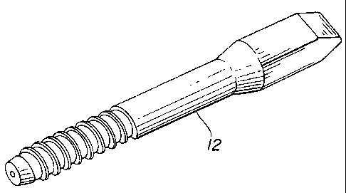
Figure 2 is a perspective view of a partially demineralized screw
according to the invention;
Figure 3 is a perspective view of a partially demineralized anchor
according to the invention;
Figure 4 is a perspective view of a partially demineralized wedge
according to the invention;
Figure 5 is a perspective view of a partially demineralized fusion ring
according to the invention;
Figure 6 is a perspective view of a partially demineralized composite
structure according to the invention;
CA 02357983 2001-10-02
7
Figure 7 is a photograph of a 35X enlarged cross sectional view of a partially
demineralized rod treated with 0.6N HC1 for 30 minutes;
Figure 8 is a photograph of a 35X enlarged cross sectional view of a partially
demineralized rod treated with 0.6N HCI for 60 minutes;
Figure 9 is a photograph of a 35X enlarged cross sectional view of a partially
demineralized rod treated with 0.6N HCI for 90 minutes;
Figure 10 is a photograph of a 35X enlarged cross sectional view of a
partially
demineralized rod treated with 0.6N HCl for 120 minutes;
Figure 11 is a photograph of a 35X enlarged cross sectional view of a
partially
demineralized rod treated with 0.6N HCl for 180 minutes;
Figure 12 is a graph showing bending displacement in relation to acid soak
ti.me; and
Figure 13 is a graph showing weight loss during partial demineralization in
relation
to acid soak time.
DETAILED DESCRIPTION OF THE IIWENTION
The present invention is directed towards a treated partially demineralized
cortical
bone construct which can be placed in a bone defect area to heal bone defects.
The term cortical
bone construct means any shaped bone device such as rods, pins, dowels,
screws, plates, wedges,
fusion rings, intervertaebral spacers and composite assemblies. The
aforementioned listing is
exemplary only and is not to construed as restrictive.
The preferred embodiment and the best mode as shown in Figures 1 and 7-11 and
shows a cylindrical cortical bone construct 10 with its surface 12 modified by
acid treatment to
remove a layer of the inorganic, mineral, hydroxyapatite bone material in such
a way as to leave the
mechanical properties substantially unchanged. While the bone material is
referred to as
hydroxyapatite in this application, in actuality the chemistry and structure
of natural bone mineral
is different as natural bone mineral contains carbonate ions, magnesium,
sodium, hydrogen phosphate
ions and trace elements and a different crystalline structure than
hydroxyapatite.
The unique features of bone that makes it desirable as a surgical material
are, its
ability to slowly resorb and be integrated into the space it occupies while
allowing the bodies own
healing mechanism to restore the repairing bone to its natural shape and
function by a mechanism
known in the art as creeping substitution. The second feature is the high
mechanical strength arising
from the collagen fiber reinforced hydroxyapatite compound structure. The
creeping substitution
mechanism, takes considerable time and some forms of cortical bone in their
natural, unmodified
CA 02357983 2001-10-02
8
biological state have been found to persist for over one year before
completely remodeling. Thus
a means of accelerating the rate ofbiointegration of cortical bone would
improve the rate of healing
and benefit the recipient patient.
It is well known that bone contains osteoinductive elements known as bone
morphogenetic proteins (BMP). These BMP's are present within the compound
structure of cortical
bone and are present at a very low concentrations, e.g. 0.003%. Based upon the
work of Marshall
Urist as shown in United States Patent Number 4,294,753, issued October 13,
1981 the proper
demineralization of cortical bone will expose the BMP and present these
osteoinductive factors to
the surface ofthe demineralized material rendering it significantly more
osteoinductive. The removal
of the bone mineral leaves exposed portions of collagen fibers allowing the
addition of BMP's and
other desirable additives to be introduced to the demineralized outer treated
surface of the bone
structure and thereby enhances the healing rate of the cortical bone in
surgical procedures. The
treatment process also exposes the naturally occurring BMP's at the surface
and renders the surface
with biological properties similar to full demineralized bone (DBM). The inner
mass 14 of the bone
mineral of the shaped construct would be left intact to contain the naturally
occurring BMP's and
trace elements as noted above. Such a product would be beneficial in spinal
fusion, fracture fixation
and similar orthopaedic and neurological procedures where rapid healing
without loss of strength
of implant is required. Partially demineralized rods 16 as shown in Figures 1
and Figures 7-11 will
retain various degrees of stiffness inversely proportional to the degree of
demineralization and
retention of core mass. The partially demineralized rods have a demineralized
outer section 18 of
exposed collagen matrix and a cortical bone core 20.
Experiments conducted by the Applicants have discovered that the surface of
cortical
bone constructs can be modified by acid treatment to remove a layer of the
inorganic, mineral,
hydroxyapatite material in such a way as to leave the mechanical properties
substantially unchanged
or to provide a construct having suitable compression and bending strength.
This then allows the
addition of BMP's and other desirable additives to be introduced to the
surface and thereby enhance
the healing rate of the cortical bone in surgical procedures. The process also
exposes the naturally
occurring BMP's near the surface and renders the surface with biological
properties similar to fully
demineralized bone (DMB). The inner mass of the bone construct would be lefft
intact to contain the
naturally occurring BMP's.
It was found that when allograft cortical pins of 2.0 mm diameter were treated
as
noted below in Example 1; and the pins were soaked for 15 to 30 minutes in a
0:6N solution of HCI
that there was minimal loss of bending strength of the rod even when the
diameter of the rod was
CA 02357983 2001-10-02
9
reduced from 3 to 5 % and the outer layer was demineralized. The denvneralized
layer ranged from
about.05 to about 0.08mm reducing the mineralized portion diameter from 0.10mm
to 0.16mm after
15 to 30 minutes of soaking in the 0.6N HCl acid bath.
Example 1
Allograft cortical bone pins were prepared by machining femoral or tibial
cortical
bone. Pins were prepared with diameter of approxima.tely 2.0 mm and a length
of 4 cm. The bulk
bone segments from which the pins were cut were chemically cleaned before
machining by soaking:
1) 30 minutes in an aqueous antibiotic solution of Gentamycin.
This reduces and eliminates any bioburden introduced by
handling the bone.
2) 30 minutes in an aqueous detergent at 95 F using ultrasonic
energy to enhance penetration. This loosens and removes the
lipid elements present in and on the bone.
3) 60 minutes in a 70/30 %v/v ethanol/water solution. This
further removes any lipid elements remaining after the
detergent wash in step 2, above.
4) The final cut pins were given a final soak in a fresh solution
of the ethanoUwater cleaning solution.
5) The pins were cut in half and then immersed in a 0.6 N
solution of Hydrochloric Acid (HCl). Half of each pin was
immersed for varying times and the other half was retained as
an untreated control.
6) The acid treatment was done at room temperature, 23 C.
7) Acid immersion was done for 30, 60, 90, 120 and 180
minutes. The pins were immersed in the acid solution and
agitated with gentle mechanical stirring.
8) After the appropriate elapsed time the pins were removed,
washed with sterile, pure (USP Sterile) water until the wash
discard was at neutral pH.
9) The pins were then lyophilized and packaged in a moisture
permeable container.
CA 02357983 2001-10-02
For purpose of this example, the above treatments were done in a laboratory
setting.
In a commercial process, the procedures would be done in a sterile, clean room
facility.
The acid treatment can be controlled to remove a sma.ll layer ofthe bone
mineral layer
leaving a highly porous and compressible surface layer while inducing no
change to the inner mass
of the construct. By controlling the acid concentration, temperature and time
of exposure, a layer
up to 0.06mm can be removed and a layer 0.08mm demineralized and have the
cortical pin
experience substantially no loss of mechanical properties as measured by a
three-point bending test.
This is an unexpected result in that mass loss should have a deleterious
effect on bending resistance
since the bending moment of a cylindrical beam is a function of the third
power of the diameter.
The surface demineralized pins were characterized as follows:
Demineralization Time Weight Loss. %
[0.6 N HC1 @ 23 C] (n = 3)
AveraQe Std Dev
30 minutes 31.8 3.2
60 38.1 1.9
90 48.2 1.2
120 56.1 6.4
180 64.9 2.9
The thickness of the demineralized layer was also measured. For each treated
pin, the
thickness of the demineralized layer was measured six times by starting at the
top of the bone
traveling clockwise approximately 60 . The following data was measured:
Demineralization Time Thickness of Demineralized LaYer
[0.6 N HCl @ 23 C] (mm)
Averaze (n = 6)
30 minutes 0.08
60 0.11
90 0.14
120 0.17
180 0.25
The treated and control pins were subjected to a three-point bending test.
Force -
displacement calculations were made from the test results as are shown in
Figure 12. Bending
displacement appears to be directly proportional to the acid soak time after
30 minutes. It is
CA 02357983 2001-10-02
11
noteworthy that the bending displacement is equivalent for the 30 minute soak
time and the
untreated control. Also note that the 30 minute acid treatment did reduce the
diameter of the pin
0.12 mm.
Scanning electron micrographs ofthe treated and control pins were made and can
be
seen in the Figures 7, 8, 9, 10, and 11 reflecting photographs of the same. It
can be clearly seen that
the Haversian canals can be seen in the cross-section of the acid treated pins
and show the removal
of the mineral layer at the surface at 35x, revealing the open pores in the
demineralized layer exposed
by the acid treatment.
This data demonstrates that surface demineralization can be achieved to remove
significant amounts of the surface mineral layer without affecting the bulk
mechanical strength.
Similar treatments were done for other machined cortical shapes using 0.6N HCl
at
23 C'for 10 minutes:
Example 2 Anterior lumbar intervertebral fusion ring (FRA)
Example 3 Posterior lumbar intervertebral fusion block (PLIF)
Example 4 Anterior cervical fusion ring (ACF)
Example 5 Allograft bone screw.
In all these examples, the surface of the machined cortical shape was modified
without
loss of the key details and dimensions machined into the surface.
The following shows the diameter change, the change in surface morphology, and
the
size ofthe demineralized layers in cylindrical pins that were demineralized in
0.6N HCl in 30, 60, 90,
120, and 180 minutes.
1. Diameter chMe:
The diameter of each pin was measured in 3 places along the pin. The
measurements
were recorded on the length of the photograph at 1.5cm, 6.5cm, and 11.5 cm on
the pin. Each
measurement is recorded in the tables below. The bottom column in each
"difference between the
treated and untreated pins" is the actual size difference. The pin was
magnified X35 so that the
measurements were each divided by 35 to arrive at the actual difference
diameter change.
Pin 1- 30 minute soak
Untreated: Left Side Middle Right Side
Pin 1-Bl
Measurement 6.6cm 6.4cm 6.5cm
CA 02357983 2001-10-02
12
Treated: Left Side Middle Right Side
Pin 1-B2
Measurement 6.0cm 6.0cm 6.2cm
Difference between the treated and untreated pins
Left Side Middle Right Side
Measurement 0.6cm 0.4cm 0.3cm
Actual 0.017cm 0.011 cm 0.009cm
Difference Average diameter change for pin 1: 0.012cm 0.12mm
Pin 2- 60 minute soak
Untreated: Left Side Middle Right Side
Pin 2-A2
Measurement 6.9cm 7.1cm 6.5cm
Treated: Left Side Middle Right Side
Pin 2-A2
Measurement 6.3cm 6.3cm 6.2cm
Difference between the treated and untreated pins
Left Side Middle Right Side
Measurement 0.6cm 0.8cm 0.3cm
Actual 0.017cm 0.023cm 0.009cm
difference
Average diameter change for pin 2: 0.016cm 0.1~ 6mm)
Pin 3- 90 minute soak
Untreated: Left Side Middle Right Side
Pin 3-C1
Measurement 7.1cm 7.1cm 6.9cm
CA 02357983 2001-10-02
13
Treated: Left Side Middle Right Side
Pin 3-C2
Measurement 5.9cm 5.6cm 5.4cm
Difference between the treated and untreated pins
Left Side Middle Right Side
Measurement 1.2cm 1.5cm 1.5cm
Actual 0.034cm 0.043cm 0.043cm
difference
Average diameter change for pin 3: 0.040cm 0.( 40mm)
Pin 4 - 120 minute soak
Untreated: Left Side Middle Right Side
Pin 4-Al
Measurement 6.9cm 6.8cm 6.6cm
Treated: Left Side Middle Right Side
Pin 4-A2
Measurement 5.1cm 5.2cm 4.9cm
Difference between the treated and untreated pins
Left Side Middle Right Side
Measurement 1.8cm 1.6 1.7
Actual 0.051 cm 0.046cm 0.049cm
Difference Average diameter change for pin 4: 0.049cm 0.~ 49mm)
Pin 5 -180 minute soak
Untreated: Left Side Middle Right Side
Pin 5-A2
Measurement 6.9cm 6.9cm 6.7cm
CA 02357983 2001-10-02
14
Treated: Left Side Middle Right Side
Pin 5-A2
Measurement 5.3cm 4.6cm 5.0cm
Difference between the treated and untreated pins
Left Side Middle Right Side
Measurement 1.6cm 2.3cm 1.3cm
Actual 0.046cm 0.066cm 0.037cm
difference
Average diameter change for pin 5: 0.050cm 0.50mm
2. Surface Morpholo~y:
The surfaces of the treated pins were compared to the surfaces of the
untreated pins.
Pin Surface Morphology
Number
1-B 1 Particles are held very tightly together. There are small gaps in the
bone. It
looks somewhat rigid.
1-B2 Looks looser than 1-B1. Very rough looking. Can see loose particles.
There are
man holes in the bone. Appears to have more dirnension/de th than 1-B 1.
Pin Surface Morphology
Number
2-Al Particles are held t' t together. There are man small gaps in the bone.
2-A2 There are many particles. The gaps are wider than 2-Al.
Pin Surface Morphology
Number
3-C1 Very dense and ' id-loo '. Particles are held t' t together.
3-C2 Not as dense as 3-C 1. There are many small surface holes and a couple of
loose
particles.
Pin Surface Morphology
Number
4-Al Particles held tightly together. Surface appears ve
CA 02357983 2001-10-02
4-A2 Surface smoother than 4-Al . There are many surface holes (some deep
enough
to see the next layer some just formin . A couple of loose particles.
Pin Surface Morphology
Number
5-Al Very dense and ' id. Small gaps.
5-A2 Smoother than 5-Al. Many surface holes. Towards the top of the slide, the
bone
b . Gaps are wider than in 5-Al.
3. Thickness of the Demineralized Layer:
For each treated pin, the thickness of the demineralized layer was measured 6
times and
the average per pin was calculated and recorded. Note: The measurements
started at the top of the bone
and recorded clockwise at approximately 60 intervals. (A magnifying glass
with a cm ruler on it was
used to measure the demineralized layer of each pin).
Pin Measurement Number Average
Number Thickness
1 2 3 4 5 6
1-B2 0.09mm 0.09mm 0.06mm 0.1 l mm 0.06mm 0.09mm 0.08mm
2-A2 0.11 mm 0.09mm 0.09mm 0.11mm 0.14mm 0.11 mm 0.11 mm
3-C2 0.14mm 0.06mm 0.03mm 0.17mm 0.29mm 0.14mm 0.14mm
4-A2 0.17mm 0.20mm 0.20mm 0.17mm 0.11nun 0.14mm 0.17mm
5-A2 0.26mm 0.23mm 0.20mm 0.23mm 0.29mm 0.29mm 0.25mm
4. Results:
The length of acid soak has an effect on the diameter of the pin. While longer
the pin is
soaked in 0.6N HCI, the more the diameter changes in size (the diameter gets
smaller), a relatively
constant diameter was reached after the 120 minutes of soak in the HCC. The
average diameter change
for the pin soaked for 30 minutes was 0.12mm; for 60 minutes was 0.16mm; for
90 minutes was
0.40mm; and for 120 minutes was 0.49 mm and 180 minutes was 0.50mm. The cross-
section slides
show that while the diameter of the pins decreased at an increased anwunt from
soak minutes 60 to 90
CA 02357983 2001-10-02
16
lessening from soak minutes 90 to 120, it remaining substantially constant
thereafter. The thickness of
the demineralized layer increased almost linearly.
The surface morphology was also affected by the acid soaks. All the pins were
viewed
under a magnification of I 00x. The slides of the untreated pins looked rigid,
the particles were tightly
held into place making the bone to appear dense, and there were small gaps on
some sections of the
bones. The slides of the treated pins looked completely different than the
untreated pins. The treated-pin
slides show loose particles, surface holes, widened gaps, and the bones appear
to be less dense.
Overall, the length of acid soak time affects the three areas tested in this
study:
1. The longer the pin soaks in 0.6N HCI, the actual diameter of the
pin decreases up until 120 minutes of acid soak.
2. The longer the pin is in the acid soak, the thickness of the
demineralized layer on the bone increases and the core
mineralized portion decreases.
3. The acid also has an effect on the surface morphology of the
bone. It changes the surface morphology from appearing very
dense and rigid (when untreated) to having loose particles and
becoming somewhat smoother (when treated).
It is valuable to add soluble silver (e.g. AgNO3) to the surface treated
cortical bone
structure. This will provide bio-static properties to the construct, i.e., it
will inhibit any growth of
microorganisms which may be resident on the surface of the cortical tissue or
adjacent to it in the
surrounding tissue. At sufficiently high concentrations, the silver cation
will be fully biocidal. Thus,
silver ranging from 10 to 10,000 parts per million may be used.
It is also envisioned to add soluble silver to the surface after treatment to
provide bio-
static properties inhibiting any growth of microorganisms which may be
resident on the surfa.ce of the
cortical tissue or adjacent to it in the surrounding tissue. Silver which can
be added is can be taken from
a group consisting of silver nitrate and other soluble or slightly soluble
silver compounds such as silver
chloride, silver oxide, silver sulphate, silver phosphate, silver acetate,
silver perchlorate or silver tartrate.
It is also possible to add one or more rhBMP's to the surface of the treated
bone shape
by soaking and being able to use a significantly lower concentration of the
rare and expensive
recombinant human BMP to achieve the same acceleration ofbiointegration. The
addition of other useful
CA 02357983 2001-10-02
17
treatment agents such as vitamins, hormones, antibiotics, antiviral and other
therapeutic agents could
also be added to the surface modified layer. BMP directs the differentiation
of pluripotential
mesenchymal cells into osteoprogenitor cells which form osteoblasts. The
ability of freeze dried
demineralized cortical bone to facilitate this bone induction principle using
BMP present in the bone is
well known in the art. However, the amount of BMP varies in the bone depending
on the age of the
bone donor and the bone processing. Sterilization is an additional problem in
processing human bone
for medical use as boiling, autoclaving or irradiation over 2.01vlrads is
sufficient to destroy or alter the
BMP present in the bone matrix.
The time, temperature and acid concentration can be adjusted to achieve a set
of process
conditions that will give the same physical result as the above noted
examples. Temperature could be
lowered to 4 C and allow the process time to increase to one hour (a four fold
increase in process time).
Temperatures much above 30 C will result in too rapid a rate of
hydroxyapatite removal and result in
a highly variable shape. Conditions could be adjusted to use acid
concentrations from about 0.IN to
about 2.ON HC1. Lower concentrations will result in a very slow rate of
mineral layer removal, not
conducive to a conunercial process. Higher concentrations will result in a too
rapid rate of mineral
removal and to a highly varied and uncontrolled surface. Other acids could be
used; sulfuric, phosphoric
or other mineral acids, organic acids such as acetic; chelating agents such as
ethylene diamine tetra acetic
acid or other weak acids would also be suitable.
Any number ofinedically useful substances can be incorporated in the invention
by adding
the substances to the composition at any steps in the mixing process or
directly to the final composition.
Such substances include collagen and insoluble collagen derivatives,
hydroxyapatite and soluble solids
and/or liquids dissolved therein. Also included are antiviricides such as
those effective against HIV and
hepatitis; antimicrobial andlor antibiotics such as erythromycin, bacitracin,
neomycin, penicillin,
polymyxin B, tetracycline, viomycin, chloromycetin and streptomycin,
cefazolin, ampicillin, azactam,
tobramycin, clindamycin and gentamycin. It is also envisioned that amino
acids, peptides, vitamins, co-
factors for protein synthesis; hormones; endocrine tissue or tissue fiagments;
synthesizers; enzymes such
as collagenase, peptidases, oxidases; polymer cell scaffolds with parenchymal
cells; angiogenic drugs and
polymeric carriers containing such drugs; collagen lattices; biocompatible
surface active agents, antigenic
agents; cytoskeletal agents; cartilage fragments, living cells such as
chondrocytes, bone marrow cells,
mesenchymal stem cells, natural extracts, tissue transplants, bioadhesives,
transforming growth factor
CA 02357983 2001-10-02
18
(TGF-beta), insulin-like growth factor (IGF- 1); growth hormones such as
somatotropin; bone digestors;
antitumor agents; fibronectin; cellular attractants and attachment agents;
immuno-suppressants;
permeation enhancers, e.g. fatty acid esters such as laureate, myristate and
stearate monoesters of
polyethylene glycol, enamine derivatives, alpha.-keto aldehydes can be added
to the composition.
All products can also be done in an aseptic environment to maintain a sterile
final product
or sterilized affter production. The cortical bone structure is then placed in
a moisture permeable inner
container which is placed in a moisture barrier outer container.
The principles, preferred embodiments and modes of operation of the present
invention
have been described in the foregoing specification. However, the invention
should not be construed as
Iimited to the particular embodiments which have been described above.
Instead, the embodiments
described here should be regarded as illustrative rather than restrictive.
Variations and changes may be
made by others without departing from the scope of the present invention as
defined by the following
claims: