Note: Descriptions are shown in the official language in which they were submitted.
CA 02358016 2001-10-02
METHOD AND APPARATUS FOR USE IN
MANUFACTURE OF CELLULOSE CASING
TECHNICAL FIELD
The present invention relates to a method and apparatus of forming a seamless
cellulose tube, suitable for use as a food casing, using a solution of
nonderivatized cellulose,
tertiary amine N-oxide and water, and to the seamless cellulose tube formed
using this
method, where such tube, when used as a casing, is easily peelable from the
food product
cooked within the casing.
BACKGROUND OF THE INVENTION
Cellulose food casings are well known in the art and are widely used in the
production of stuffed food products such as sausages and the like. Cellulose
food casings
used in the manufacture of small diameter sausages such as frankfurters and
the like
generally are seamless tubes formed of a regenerated cellulose and contain a
plasticizes such
as water and/or a polyol such as glycerin. Without plasticization, the
cellulose tube is too
brittle for handling and commercial use.
Cellulose food casings of pure regenerated and non-reinforced cellulose for
the
manufacture of frankfurters generally have a wall thickness ranging from about
0.025 mm to
about 0.076 mm and are made in tube diameters of about 14.5 mm to 203.2 mm.
These
casings are hereinafter referred to simply as "cellulose casing".
C:\windows\TEMP\D20214 Prov. mandrel.doc 1
CA 02358016 2001-10-02
Cellulose casing is most commonly produced by the well known and so called
"viscose process", wherein viscose, a soluble cellulose derivative, is
extruded as a tubular
film. The annular extrusion die extends through the bottom of a coagulating
and
regenerating bath so that the extrusion proceeds in an upward direction
through the bath. By
extruding upwardly directly into the regenerating bath, the bath liquid
supports the extrusion
which is fragile and not self supporting during the initial phase of
regeneration. After
sufficient regeneration to be self supporting, the tube undergoes additional
processing steps
and is then washed, plasticized with glycerin or other polyol, and dried.
Drying usually is
accomplished while the tube is inflated with air at a pressure sufficient both
to maintain a
constant tube diameter and to orient the film.
Food casings typically contain additives or coatings to enhance food
processing and
food characteristics, such as colorants that are incorporated into the casing
to make self
coloring casings or liquid smokes, which impart a smoky flavor and a reddish
color to the
sausage.
Casings are used for the production of skinless sausages. Emulsified meat is
stuffed
into a casing, which is pinched off at intervals to form the sausages. The
linked sausages are
cooked and smoked, to flavor, denature and coagulate the protein in the outer
layer of the
sausage, and then cooled to set the coagulated protein. The cooked, smoked
sausages are
then showered to humidify them fully and relax the skin, which is then
stripped off, leaving
firm, skinless sausages. It has been found that when the casing is peeled from
the cooked
sausages, the meat may adhere to the casing during the stripping step and is
pulled away,
resulting in a commercially unacceptable product. Peeling aids that allow the
casing to be
completely stripped off the cooked meat product without causing any of the
meat product to
be damaged are also an important component of commercial casing.
C:\windows\TEMP\D20214 Prov. mandrel.doc 2
CA 02358016 2001-10-02
The present invention involves an alternate cellulose production method in
which a
cellulose solution is formed by means of a simple dissolution rather than
requiring the
formation of a cellulose derivative prior to forming a soluble substance (as
in the viscose
process). A cellulose dissolution process is described, for example, in U.S.
Patent No.
2,179,181 ("' 181 "), where a natural cellulose is dissolved by a tertiary
amine N-oxide to
produce solutions of relatively low solids content. The cellulose in the
resulting solution is
"nonderivatized" in that the natural cellulose was not chemically reacted
prior to dissolution
to produce a soluble cellulose derivative as would occur for example, in the
viscose process.
U.S. Patent No. 3,447,939 ("'939") discloses use of N-methyl-morpholine-N-
oxide
("NMMO") as the tertiary amine N-oxide solvent where the resulting solutions,
while
having a low solids content, nevertheless can be used in chemical reactions
involving the
dissolved compound, or to precipitate the cellulose to form a film or
filament.
More recent patents such as U.S. Patent Nos. 4,145,532 and 4,426,288 improve
upon
the teachings of the '939 Patent.
U.S. Patent No. 5,277,857 ("'857") discloses a method and apparatus for
manufacturing cellulose food casing from a solution comprising nonderivatized
cellulose,
NMMO and water.
In '857, nonderivatized cellulose in a molten state, contrary to the viscose
process, is
extruded as a tubular film downwardly through an air space and into a
nonsolvent liquid,
such as a water bath. In the water bath, the NMMO solvent is removed to
regenerate or
precipitate the nonderivatized cellulose, which is then washed of residual
solvent,
plasticized and dried.
C:\windows\TEMP\D20214 Prov. mandrel.doc
CA 02358016 2001-10-02
In U.S. Patent No. 5,451,364 ("'364"), the manufacturing method as disclosed
in the
prior '857 is improved by the discovery that extruding the thermoplastic
cellulose solution
through a long air gap improves the properties of the resulting tubular
cellulose film. In
particular, '364 discloses that the air gap should be over 152.4 mm and
preferably from
152.4 mm to 304.88 mm long and perhaps longer.
Both '364 and '857 further disclose the use of a mandrel that depends from the
extrusion die and about which the thermoplastic cellulose solution is
extruded. This
mandrel extends through the air gap and has its lower end face disposed below
the level of
the nonsolvent liquid bath. The mandrel for most of its length is a slender
shaft. The lower
portion, however, is larger in diameter and is as large as, or larger than,
the extruded tube
diameter so it contacts around the entire inner circumference of the extruded
tube. The
mandrel shaft, being smaller in diameter, is radially spaced from the inner
surface of the
extruded tube.
The large diameter lower portion of the mandrel serves to size the tube as it
enters
the bath. Also, since it contacts the extruded tube, the enlarged lower
portion of the mandrel
together with the extrusion die provide spaced bearing points for stabilizing
the extruded
tube and preventing it from wandering.
The mandrel also is used to introduce a nonsolvent liquid into the interior of
the
extruded tube. One function of this introduced nonsolvent liquid, among
others, is to
lubricate around the circumference of the lower portion of the mandrel to
prevent the
extruded tube from binding as it passes over the surface of the lower portion
or blocking
when it later is collapsed to a flat width.
C:\windows\TEMP\D20214 Prov. mandrel.doc
CA 02358016 2001-10-02
In this regard, a nonsolvent liquid or "inner bath" is introduced inside the
extruded
tube through ports in the mandrel shaft. This inner bath flows down the
mandrel and pools
where the extruded tube meets the enlarged lower end of the mandrel. This
pooling
distributes the nonsolvent around the mandrel so the entire outer
circumference of the
mandrel lower portion is wetted. Nonsolvent liquid then flows off the mandrel
and to the
bath within the extruded tube.
U.S. Patent No. 5,766,540 discloses a mandrel structure allowing extrusion
through
even longer air gaps of up to 500 mm or more.
U.S. Patent No. 5,759,478 discloses that certain properties of the cellulose
film
formed by the tubular extrusion as described in '857 are enhanced by
increasing the length
of the enlarged lower or "sizing portion" of the mandrel. It is speculated
that maintaining the
extruded tube in a stretched condition for a longer time by keeping it in
contact with the
sizing portion of the mandrel allows desirable orientation characteristics of
the gel tube to
"set" during the solvent extraction process. Whatever the reason, a longer
contact time with
the sizing portion of the mandrel was desirable and '478 indicates that a
preferred length of
the sizing portion is about 50 mm.
However, as disclosed in '478, increasing the length of the sizing portion of
the
mandrel gives rise to another problem. This involves the removal of gas
bubbles from the
interface between the surface of the sizing portion and the inside surface of
the extruded
tube that likely are formed by out-gassing of air from the extruded tube. In
'478, these
bubbles are removed through a series of interconnected circumferential grooves
formed in
the surface of the sizing portion.
C:\windows\TEMP\D20214 Prov. mandrel.doc 5
CA 02358016 2001-10-02
It now has been found that both the stability of the extrusion process and
properties
of the casing are further improved when the length of the sizing portion is
increased to
lengths greater than the 50 mm disclosed in '478. Increasing the length of the
sizing portion
necessitated additional circumferential grooves to provide for the removal of
gas bubbles.
However, adding more grooves made difficult the drawing of the leading end of
the
extrusion over the sizing portion on the start-up of extrusion. This is
because the increase in
the number of grooves increased the likelihood of the leading end of the
extrusion snagging
on the edge of a groove.
Also, contrary to earlier belief, the additional grooves did not act as air
bearings that
facilitated the passage of the extrusion over the sizing portion. Instead,
each additional
groove added an amount of frictional force so that the total drag caused by
the extrusion
passing over the many circumferential grooves was incompatible with the smooth
passage
of the extrusion over the mandrel sizing portion. With too many grooves, the
frictional
force may become so great that the extrusion breaks rather than being pulled
over the
mandrel. Accordingly, the addition of grooves to provide for gas removal as
taught by '478
limited the mandrel length and interfered with the benefits that were seen
from the use of a
mandrel longer than 50 mm. Thus, while it was found that mandrels of up to 152
mm or
more were desirable from the standpoint of the stability of the extrusion
process and casing
properties, the additional circumferential grooves needed to accommodate gas
removal over
this length prevented use of the more desirable longer length mandrel.
Accordingly, it is an object of the present invention to provide an improved
apparatus and method for extruding a seamless tube of a thermoplastic
nonderivatized
cellulose solution to permit the use of a mandrel having a longer sizing
portion to
C:\windows\TEMP\D20214 Prov. mandrel.doc
CA 02358016 2001-10-02
diametrically expand the extruded tube including means to accommodate and
remove gas
bubbles that are generated at the interface between the surface of the sizing
portion and the
inner surface of the extruded tube.
Once produced, by either the viscose process or the nonderivatized process,
the
various additives and peeling aids can be added to the casing by various
methods, such as
dipping or spraying the relevant materials onto the formed casing. While it is
well known
that regenerated casings made with the viscose process are able to accept
these additives and
coatings and produce casing that peels readily from the cooked meat product,
it is not well
known how casings made from the nonderivatized process would accept such
additives.
Therefore, it is also an object of the present invention to provide an
improved
method of making a nonderivatized casing that peels readily from cooked
sausages.
Additionally, another object of the present invention is to provide the
improved
nonderivatized casing itself.
SUMMARY OF THE INVENTION
In the present invention, a tube of thermoplastic nonderivatized cellulose is
downwardly extruded through a long air gap and into a bath of nonsolvent
liquid as is
generally disclosed in both '857 and '364.
For purposes of this specification, "nonderivatized" cellulose means a
cellulose that
has not been subjected to covalent bonding with a solvent or reagent but that
has been
dissolved by association with a solvent or reagent through van der Waals
forces, such as
hydrogen bonding. "Nonsolvent" means a liquid that is not a cellulose solvent.
C:\windows\TEMP\D20214 Prov. mandrel.doc
CA 02358016 2001-10-02
As shown in '857 and '364, extrusion is about a mandrel which depends from the
extrusion die. The mandrel has a shaft portion and a tapered lower end
portion, wherein all
diameters of the lower end portion are larger in diameter than the shaft. The
lower end or
"sizing portion" of the mandrel has a diameter larger than the extruded
diameter of the
thermoplastic tube so the tube is stretched as it passes over the sizing
portion, . In another
embodiment, instead of having a tapered lower end portion, the lower end will
have at least
two constant diameter sections, both larger in diameter than the shaft,
connected by at least
one diametrically expanding section. As noted above, gas bubbles tend to
generate at the
interface between the outer surface of the sizing portion and the inside
surface of the
extruded tube. In the present invention, the sizing portion is hollow for most
of its length
and openings in the outer surface of the sizing portion provide passages to
conduct these
bubbles directly from the surface to the hollow interior of the sizing
portion. A conduit
extending up from the hollow interior and through the shaft portion provides
for the removal
of gas from the hollow interior of the sizing portion.
Accordingly, the invention may be characterized in one aspect by an apparatus
for
extruding a seamless tubular film from a thermoplastic solution composed of
nonderivatized
cellulose, a tertiary amine oxide cellulose solvent, and water by extruding a
tube of the
solution downwardly from an annular die, through an air space and into an
outer bath of a
nonsolvent liquid for regenerating the cellulose from the solution, the
extrusion being about
a mandrel comprising a shaft which depends from the die and extends through
the air space
and a sizing portion at a lower end of the shaft located adjacent to a conical
transition
section and that is disposed for all, or the majority of its length, below the
level of the liquid
in the bath.
C:\windows\TEMP\D20214 Prov. mandrel.doc
CA 02358016 2001-10-02
The sizing portion is formed by an annular wall that defines a hollow cylinder
having a length of from 60 to 152.4 mm or more and an outside diameter greater
than the
diameter of the tubular extrusion. In one embodiment, the sizing portion is
tapered, wherein
all diameters of the lower end portion are greater in diameter than the
diameter of the tubular
extrusion, and where the outside diameter of the lowermost end face of the
sizing portion is
greater than the diameter of the widest edge of the conical transition
section.. The outer
surface of the sizing portion is smooth and is provided with a plurality of
openings that
extend through the annular wall to the hollow interior of the cylinder. These
openings allow
gas bubbles generated at the interface between the outer surface of the sizing
portion and the
inner surface of the extrusion to pass through the annular wall directly into
the hollow
interior of the sizing portion. Preferably, the openings are arranged such
that any drag
created as the extrusion passes over the openings does not create a moment of
force tending
to turn or twist the extrusion with respect to the sizing portion.
From the interior of the sizing portion, the gas is removed upwardly through a
conduit in the stem that opens into the hollow cylinder.
In another aspect, the present invention may be characterized by a method of:
a) forming a seamless cellulose tube by downwardly extruding a tube of
thermoplastic solution composed of nonderivatized cellulose, a tertiary amine
oxide and
water through an air gap and into a nonsolvent bath;
b) during the course of extruding, causing the extrusion to pass over and
about a
vertically oriented mandrel having a sizing portion generally in the shape of
a tapered
hollow cylinder, where all diameters of the tapered hollow cylinder are larger
than the
extruded tube, and a length of 60 to 152.4 mm or more, the mandrel having a
smooth
surface provided with a plurality of openings to the interior of the hollow
cylinder;
C:\windows\TEMP\D20214 Prov. mandrel.doc
CA 02358016 2001-10-02
c) passing gas bubbles evolving from the extruded tube at the interface
between the
extruded tube and sizing portion through the openings and into the hollow
interior; and
d) removing the gas from the hollow interior upwardly through the mandrel.
Another aspect of this invention is a tubular cellulose film made of
nonderivatized
cellulose precipitated from an extruded thermoplastic cellulose solution of
cellulose, a
tertiary amine oxide, and water, wherein said tubular film exhibits improved
peeling
characteristics.
Another aspect of this invention is a tubular extrusion formed of a
thermoplastic
cellulose solution composed of a nonderivatized cellulose, a tertiary amine
oxide cellulose
solvent, and water, produced by the process comprising:
a) forming a seamless cellulose tube by downwardly extruding a tube of
thermoplastic solution composed of nonderivatized cellulose, a tertiary amine
oxide, and
water through an air gap and into a nonsolvent bath;
b) during the course of extruding, causing the extrusion to pass over and
about a vertically oriented mandrel having a sizing portion generally in the
shape of a
hollow cylinder that has a diameter larger than the extruded tube and having a
diameter at
the point the sizing portion is adjacent to a conical transition cylinder
being the same as the
adjacent edge of the conical transition cylinder and a diameter of a lowermost
end face
being greater than the diameter of the widest edge of the conical transition
section, the
mandrel having a lower end disposed below the level of the bath and a smooth
outer surface
provided with a plurality of openings to the interior of the hollow cylinder;
c) passing gas bubbles evolving from the extruded tube at the interface
between the extruded tube and sizing portion through the openings and into the
hollow
interior; and
C:\windows\TEMP\D20214 Prov. mandrel.doc 1 O
CA 02358016 2001-10-02
d) removing the gas from the hollow interior upwardly through the mandrel.
Other objects and advantages of this invention will be apparent from the
ensuing
detailed disclosure and appended claims.
DESCRIPTION OF THE DRAWINGS
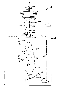
Figure 1 is a schematic view showing the apparatus of the present invention
during
the course of steady-state extrusion;
Figure 2 is a view on an enlarged scale, partly broken away and in section
showing
the sizing portion of the mandrel in greater detail; Figure 3 is a view of
another embodiment
of the tapered mandrel; and
Figure 4 is a view similar to Figure 2 showing another embodiment of the
inventive
mandrel.
DETAILED DESCRT_PTION OF THE INVENTION
Refernng to the drawings, Figure 1 shows the apparatus generally indicated at
10
during the course of steady-state operation. The apparatus includes a die 12
arranged to
downwardly extrude a thermoplastic cellulose solution. The die inlet 14
receives the molten
solution under pressure from any appropriate source (not shown). The solution
is a solution
of a natural cellulose (such as wood pulp) dissolved in a cellulose solvent
comprising
NMMO and water. Methods of making an appropriate solution ("dope") for
extrusion as a
tubular film are well known in the art and comprise no part of the present
invention.
The die has an annular extrusion orifice 15 so the molten dope is extruded as
a
seamless tube indicated at 16. For purposes of extruding a small diameter food
casing, the
extrusion orifice is about 12-16 mm in diameter. As shown in Figure 1, the die
is arranged
C:\windows\TEMP\D20214 Prov. mandrel.doc 11
CA 02358016 2001-10-02
above a vessel 18 which contains a bath 20 (some times referred to as an
"outer bath")
comprising nonsolvent liquid. Water or an aqueous solution containing a low
concentration
of NMMO are preferred nonsolvents for purposes of the present invention. The
die is
spaced well above the level 22 of the bath so the tube is extruded downwardly
through a
long air gap 24. This air gap may be 304mm to SOOmm or more in length.
Depending from the die is a mandrel, generally indicated at 26, which extends
from
the die to below the bath level 22. A preferred mandrel structure is more
particularly
disclosed in U.S. Patent No. 5,766,540. In general, the mandrel has a shaft
portion 28 and a
lower portion 30. The lower portion preferably is larger in diameter than the
diameter of the
annular extrusion orifice 15. Thus, the lower portion 30 comprises a means for
diametrically
stretching or "sizing" the extruded tube and is referred to hereafter as the
mandrel sizing
portion. The mandrel sizing portion 30, and a conical transition section 32,
preferably are
made of a hydrophobic material such as Teflon or a filled Teflon.
As the extruded tube 16 enters bath 20, the NMMO solvent is drawn from the
tube
causing regeneration of the dissolved cellulose to form a so called "gel tube"
36 of pure
cellulose. This gel tube is collapsed to a flat width by a series of fingers
or baffles 38 and
then is drawn around a driven roll 40 and directed up and out of the vessel 18
for further
processing.
The tubular extrusion process, as disclosed in '857 and '364, further includes
the
introduction of air and a nonsolvent liquid into the interior of the extruded
tube 16. Both air
and the nonsolvent, hereafter called "the inner bath", are introduced through
the mandrel. In
this respect, an air line 42 connected to the upper end of mandrel shaft 28
provides an air
flow through the mandrel to openings (not shown) in the shaft that vent the
air into the
C:\windows\TEMP\D20214 Prov. mandrel.doc 12
CA 02358016 2001-10-02
interior of the extruded tube to hold it open at the start of the extrusion
process. Nonsolvent
liquid for the inner bath likewise is introduced into the mandrel through a
line 44 that is
connected to one or more ports 46 in the mandrel shaft 28. After the
nonsolvent exits the
mandrel, it flows down the surface of the mandrel shaft 28 and flows down the
mandrel
shaft to form a pool 48. This pool provides lubrication to permit the passage
of the extruded
tube over the mandrel sizing portion 30 and starts the regeneration of the
cellulose at the
inner surface of the extruded tube. The inner bath from the pool passes down
between the
mandrel sizing portion and the extruded tube and flows into the volume SO of
bath liquid
within the tube.
As best seen in Figure 2, the mandrel sizing portion 30 is formed by an
annular wall
51 that defines a hollow cylinder between the conical transition section 32
and the
lowermost end face 34. In one preferred embodiment, the mandrel sizing portion
consists of
at least two constant diameter sections 71 and 72 of lengths 73 and 74
respectively,
connected by a diametrically expanding section 75. Constant diameter section
71 begins at
the lower edge of the conical transition section 32 and is smaller in diameter
than the
lowermost end face 34. The lowermost end face 34 of the sizing portion is open
and the
upper end 52 is slightly dome-shaped. An exhaust conduit 54 extending through
the
mandrel stem 28 opens into the hollow interior 56 adjacent the upper end 52 of
the sizing
portion. The outer surface 58 of the cylinder is smooth and unbroken except
for a plurality
of openings 60 that extend through the annular wall 51 and communicate with
the hollow
interior 56.
In another preferred embodiment, as shown in Figure 3, the mandrel sizing
portion
consists of an annular wall 51 between the lower edge of conical transition
section 32
30 and the lowermost end face 34, with the diameter of annular wall 51 being
continuously
C:\windows\TEMP\D20214 Prov. mandrel.doc 13
CA 02358016 2001-10-02
tapered over its length 76, and where annular wall 51 defines a hollow
cylinder including
the conical transition section 32 and the lowermost end face 34. All diameters
of this
mandrel sizing portion 30 are greater in diameter than the shaft and the
diameter of the
lowermost end face 34 is greater than the diameter of the lower edge of the
conical transition
section 32.
In one embodiment, the openings 60 are arranged in four rows (A, B, C and D)
extending substantially the full length of the sizing portion wherein each of
the two
diametrically opposite rows of openings 60A and 60C are spaced at 90~ around
the
circumference of the sizing portion from the two diametrically opposite rows
of openings
60B and 60D. Moreover, as shown in Figure 2, the openings of diametrically
opposite rows
A and C are longitudinally off set from the openings of the diametrically
opposite rows B
and D so that each of the holes 60A and 60C are about midway between the
openings 60B
and 60D. This arranges the openings in a diamond shape pattern 62, represented
by dotted
line 62, about the surface of the mandrel. It is believed that the placement
of the openings at
90~ intervals around the circumference of the sizing portion and the
longitudinal off set of
the openings prevent the drag created by the holes from imparting any rotary
motion to the
extruded tube around the sizing portion. This insures that the extrusion is
solely in a linear
direction with no angular motion that could adversely affect the properties of
the casing that
is produced.
When extrusion is through a long air gap of 300 mm and up to 500 mm or more,
it is
preferred that the mandrel be an extendable mandrel as disclosed in U.S.
Patent No.
5,766,540. With an extendable mandrel, extrusion is started with the mandrel
in a raised
position such that the lowermost end face 34 is above the liquid level 22.
C:\windows\TEMP\D20214 Prov. mandrel.doc 14
CA 02358016 2001-10-02
Extrusion is started and the leading end of the extruded tube 16 is drawn down
and
over the sizing portion 30. Once the leading end of the extruded tube is
beyond the mandrel
lower end face 34, the mandrel is extended to the position shown in Figure 1
wherein most,
if not all, of the mandrel sizing portion 30 is disposed below the liquid
level 22. The inner
bath introduced through ports 46 collects in a pool 48 which forms around the
lower end of
the mandrel stem. Nonsolvent liquid from this pool is earned out from between
the inner
surface of the extruded tube and the cylinder surface 58 to lubricate this
area and permit the
passage of the extruded tube over the sizing portion.
During the course of extrusion, gas bubbles may appear at the interface
between the
extruded tube 36 and the mandrel sizing portion 30. It is not known with
certainty why
these gas bubbles form. It is speculated that the gas is air which becomes
dissolved in the
molten thermoplastic solution during the formation and extrusion of the
solution. This so
called "soluble air" remains in solution so long as the molten thermoplastic
solution is under
pressure. However, once the solution is extruded, this soluble air is released
as an out gas
from the extruded tube.
In any event, a portion of gas released from the inner surface of the tube
becomes
trapped between the inner surface of the extruded tube and the surface of the
mandrel sizing
portion. The openings 60 shown in Figure 2 provide the means for allowing the
gas bubbles
to pass through the annular wall 51 and into the hollow cylinder. In this
respect, the hollow
interior of the cylinder is under a slight negative pressure created by
evacuation through
conduit 54. This draws the gas bubbles through the openings 60 and into the
hollow interior
of the mandrel sizing portion 30. The gas bubbles then rise and collect within
the mandrel
adjacent the domed upper end 52. From there, the gas is removed upwardly
through the
conduit 54 in the mandrel stem.
C:\windows\TEMP\D20214 Prov. mandrel.doc 15
CA 02358016 2001-10-02
Also, it is preferred that there be an unbroken band 59 about the sizing
portion
between the conical section 52 and the uppermost hole 60. This band, together
with the
negative pressure within the hollow cylinder tends to create a seal that
prevents gas bubble
from migrating upwardly along the surface of the mandrel sizing portion 30 and
into the
volume of the extruded tube above the sizing portion.
Occasionally however, a gas bubble may move upward into the volume within the
extruded tube above the sizing portion. If need be, the air introduced into
this volume can
be adjusted to correct for pressure variations that may be caused by the
accumulation of gas
in this space.
In accordance with the present invention, providing the mandrel sizing portion
30
with the openings 60 allows for the gathering of gas bubbles into the hollow
interior of the
sizing portion. This gathering of gas bubbles removes them to a location where
they will
not disrupt the formation of the gel tube. Further, it is preferred that the
extrusion process
be as linear as possible and that there be no moment of force tending to
impart a twist of the
extrusion about the mandrel sizing portion. Accordingly, the arrangement of
the openings
60 along the smooth cylinder surface 58 as shown is such that the drag created
as the
extrusion passes over these opening does not impart such a moment.
Another embodiment is illustrated in Figure 4. As shown in Figure 4, the
mandrel
sizing portion 30 has a plurality of openings 60 arranged so as to form a
diamond shape on
the mandrel surface 58. However, instead of four longitudinal rows of openings
as in the
Figure 2 embodiment, there are eight rows shown in Figure 4. The openings 60
in four of
the rows A, B, C and D are equally spaced at 90~ intervals around the mandrel
and are
C:\windows\TEMP\D2o214 Prov. mandrel.doc 16
CA 02358016 2001-10-02
equally spaced in the rows along the mandrel. A second set of openings 70 are
arranged in
four rows that are off set both radially and longitudinally from the openings
60 so as to
produce the diamond shape patterns on the mandrel surface represented by
dotted lines 62.
In this respect, the openings 70 arranged in the four rows A, B, C and D are
radially off set
45~ from the openings 60. The openings 70 also are longitudinally off set so
that each of the
openings 70 A, B, C and D are located about half way between the openings 60
A, B, C and
D.
Having one set of the four rows of openings 60 off set 45~ from the four rows
of
openings 70 as shown in Figure 4 minimizes the distance between openings. With
this
arrangement, gas bubbles have a shorter time to grow in size before being
drawn into one of
the openings.
In the case of a mandrel having a mandrel sizing portion 30 about 23 mm in
diameter
at the junction of the conical transition section 32 and a diameter of 28 mm
at the lowermost
end face 34, and 152.4 mm in length, a suitable arrangement as shown in Figure
4 provided
forty-four openings arranged in four rows of six openings each and four rows
of five
openings each. The unbroken band 59 just below the conical section 52 was
about 12.5 mm
wide. The openings in each of the four rows are longitudinally spaced about 25
mm apart.
Each opening is less than about 3.2 mm in diameter and preferably is about 0.8
to 1.6 mm in
diameter. Holes larger than about 3.2 mm were found to create a drag on the
extrusion
making start-up difficult. Openings smaller than about 0.8 mm in diameter were
not as
effective in passing the gas bubbles.
Thus it should be appreciated that the present invention allows use of a
mandrel
sizing portion of up to 150 mm or more in length and accommodates the removal
of gas
C:\windows\TEMP\D20214 Prov. mandret.doc 17
CA 02358016 2001-10-02
bubbles from the surface of the sizing portion without the drawbacks of having
a grooved
surface to accommodate such removal.
Additionally, the present invention includes the tubular extrusion, which is a
film or
a casing, formed of a thermoplastic cellulose solution composed of a
nonderivatized
cellulose, a tertiary amine oxide cellulose solvent, and water, produced by
the process
comprising:
a) forming a seamless cellulose tube by downwardly extruding a tube of
thermoplastic solution composed of nonderivatized cellulose, a tertiary amine
oxide, and
water through an air gap and into a nonsolvent bath;
b) during the course of extruding, causing the extrusion to pass over and
about a vertically oriented mandrel having a sizing portion generally in the
shape of a
hollow cylinder that has a diameter larger than the extruded tube and having a
diameter at
the point the sizing portion is adjacent to a conical transition cylinder
being the same as the
adjacent edge of the conical transition cylinder and a diameter of the
lowermost end face of
the sizing portion being greater than the diameter of the widest edge of the
conical transition
section, the mandrel having a lower end disposed below the level of the bath
and a smooth
outer surface provided with a plurality of openings to the interior of the
hollow cylinder;
c) passing gas bubbles evolving from the extruded tube at the interface
between the extruded tube and sizing portion through the openings and into the
hollow
interior; and
d) removing the gas from the hollow interior upwardly through the mandrel.
The sizing portion of the mandrel can be shaped as described previously,
either as
continuously tapered as seen in Fig.3, or with a plurality of constant
diameter sections
connected by continuously expanding sections, one embodiment thereof as seen
in Fig.l.
C:\windows\TEMP\D20214 Prov. mandrel.doc 18
CA 02358016 2001-10-02
In order to be commercially viable, tubular film used as casing for the
manufacture
of sausages or other stuffed meat products must have the characteristic of
being easily
peeled from the cooked sausage or meat product. A test method used to
determine this
characteristic is called the "stretch burst" test. A section of casing is
soaked in room
temperature water for thirty minutes to insure it is in a rewet condition.
Once soaked, one
end of the sample is tied off and the sample is inflated with air at a rate of
pressure increase
of about 44.52 mm Hg/sec, until it bursts. The diameter increase during
inflation and the
diameter at burst are recorded.
Casing wall thickness is roughly constant over a large range of cellulose
casing
sizes. However, as casing size increases, the slope of the stretch burst (SB)
curve increases.
The change in slope is primarily due to the hoop stress.
Cellulose casing is a thin-walled cylindrical pressure vessel. When
pressurized, in-
plane casing stress is proportional to the cylinder radius. In-plane stress in
the axial
direction is given by Equation 1. In-plane stress perpendicular to the
cylinder axis (i.e.,
around the circumference of the casing) is given by Equation 2. The value
given by
Equation 2 is also referred to as hoop stress. In Equations 1 and 2, p is
pressure, t is casing
wall thickness, and r is casing radius.
pr
y =-
2t
Equation 1: In-plane casing stress in the axial direction.
pr
- t
C:\windows\TEMP\D20214 Prov. mandrel.doc 19
CA 02358016 2001-10-02
Equation 2: Hoop stress in a cylindrical pressure vessel.
The effect of hoop stress can be seen in Table 1. Table 1 shows the effect of
rewet
flat width ("RFW") on the ratio of RFW and 150 mm Hg diameter for a variety of
Nucel
casing sizes. The ratio of RFW and 150 mm Hg diameter is a measure of casing
SB slope.
Table 1 also contains wall thickness values expressed as the ratio of RFW
divided by casing
bone dry gauge (BDG). Even though wall thickness (t) varies only slightly over
the range of
casing sizes shown in Table 1, the casing slope steadily increases over the
range of casing
sizes shown in Table 1.
SB Slope -~- W all Thickness Linear (SB Slope) 'i
1.32 _ ___._. _ _ ~ 0.08
1.3 ._ ___-- - 0.07
0
1.28 _ _ __..__ ~_ i m
~ 0.06
. _. -___ _ _..-..-- _
1
26
. . _ -_ _
.
0.05
~n
D 1.24 __ ____-_ _ _ .. _. _._ . T
___ _--_
d
~
_______ - - ' 0.04
1.22 ... ___.-__. _
2 .__- -__-_ ___
1
. ~ 0.03 ~
R
_ _-- -
1.18 _- m
+ 0.02
1 _ _-
.16 _.__._-_
_ 0.01 ~j
1
14
- _
.
--
1.12 _._.__._ T_ - p
0.75 1 1.25 1.5 1.75 2
RFW (inches)
Table 2: Effect of casing size on SB slope.
C:\windows\TEMP\D20214 Prov. mandrel.doc 20
CA 02358016 2001-10-02
Casings made by the viscose process, known as 25N NoJax~ (a registered
trademark
of Viskase Corporation, Chicago, Illinois, USA) have been tested with the
stretch burst test,
showing that commercially acceptable casing, with a RFW averaging 35.47 mm,
has an
average burst pressure of 271.33 mm Hg, with the average diameter at burst
being 37.33
mm.
Nonderivatized casing made using a mandrel having a constant diameter in the
sizing portion, and therefore not a mandrel of the instant invention, was
tested using this
stretch burst test. (The diameter of the casing at 50 mm Hg is denoted as D50,
and the
diameter converted to flat width at the 150 mm Hg pressure point is denoted as
F150.) This
nonderivatized casing followed the regression:
F150/RFW = (0.297 X D50) + 0.980
In order to give the best commercial peeling characteristics, the optimum
value of
the F 150/RFW point is a value of one. The 25N NoJax~ casing described above,
a
commercial casing, has a F150/RFW of 1.10. As shown in the Examples below, it
has been
discovered that the inventive nonderivatized casing produces a F150/RFW point
closer to a
value of one than do nonderivatized casings not of the present invention.
Examples 1-6. Burst Strength of Nonderivatized Casing
Nonderivatized cellulose casing made using a mandrel having a first constant
diameter section of 0.92 inches and a second constant diameter section of 1.10
inches was
tested using the stretch burst test as described above. The results are shown
in Table 2 for
Examples 2, 4, and 6. Nonderivatized cellulose casing of the same size as the
casings
C:\windows\TEMP\D20214 Prov. mandrel.doc 21
CA 02358016 2001-10-02
shown in Examples 2, 4, and 6 were made using a straight mandrel and subjected
to the
same stretch burst test. Those results are shown in Examples 1, 3, and 5
The casings of Examples 2, 4, and 6 had a F150/RFW point that was less than
that
given by the casings of Examples 1, 3, and 5 by at least 0.02 inches, and
therefore showed
improved peelability.
TABLE
2
Comparison
of
Casings
Made
with
Straight
and
Tapered
Mandrels
Ex. Casing RFW D 150 F 150 F 150/RFWD50
No.
1. Size 1.251 0.965 1.516 1.212 0.783
26a
2. Size 1.254 0.950 1.492 1.190 0.786
26b
3. Size 1.150 0.870 1.367 1.188 0.700
23a
4. Size 1.170 0.870 1.367 1.168 0.700
23
S. Size 1.340 1.051 1.651 1.232 0.848
27a
6. Size 1.318 0.986 1.549 1.175 0.815
276
= Casing sample made with a straight mandrel.
b = Casing sample made with a tapered mandrel.
C:\windows\TEMP\D20214 Prov. mandrel.doc 22