Note: Descriptions are shown in the official language in which they were submitted.
CA 02358217 2001-10-03
TITLE: FINISHING AND ABRASIVE TOOL
DISCLOSURE
[0001 ] This invention relates generally as indicated to a finishing and
abrasive tool and, more particularly, to an abrasive spinner or finishing star
tool
having enhanced flexibility and a longer useful life.
BACKGROUND OF THE INVENTION
i o [0002] Squares, cross pads and stars, called spinners, are forms of
abrasive tools and are special application abrasive tools used for a variety
of
purposes. Each uses rectangular or square pads or bundles of sand paper or
abrasive cloth with the tool being mounted on an arbor going through the
center. Square pads, for example, may be used for grinding or blending of
corners or for spot facing. As the pad rotates, the corners wear down and the
tool becomes round. They abrade or cut almost as fast as hard wheels, but are
easier to control and are more suitable for certain surfaces and shapes.
[0003] Cross pads are used for grinding, polishing and deburring as well
as spot facing. One application is the ends of tubes or holes, both inside and
2o out, for bell-mouth configurations, and chamfering. Cross pads have a
generally x-shape configuration and this allows the operator to see the work
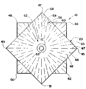
since it is not completely obscured by the tool.
[0004] A star, sometimes called a finishing star, is something of a
combination of both usually made from several packs of square abrasive sheets
25 which are offset from each other on the rotational axis of the tool. For
example, a star may be formed of at least two outside packs of abrasive sheets
and at least two inside packs, with the inside packs each aligned and the
outside packs each aligned, but the inside and outside packs offset
45°. This
produces an eight-pointed symmetrical star. Additional packs offset
so symmetrically may produce stars with more points. The packs are usually
held
together with a two-part coined or swaged hole forming fastener with internal
threads.
1
CA 02358217 2001-10-03
(0005) One of the problems with such tools is maintaining the desired
flexibility for conformance to the work, particularly edges, ridges or
projections,
while at the same time providing enough rigidity, cushion or backup to perform
the work properly. Too much of either characteristic will considerably shorten
the tool life. Accordingly, there is a need for such a tool having both
characteristics and longer tool life.
SUMMARY OF THE INVENTION
[0006] A rotary abrasive tool in the form of a star utilizes angularly offset
packs of abrasive sheets or sand paper with each sheet radially slit, but with
discontinuous slits. The discontinuous radial slits keep the slits from
forming
separate fingers which might break off in use but provide the desired surface
flexibility for proper work application. An internally threaded two-part
fastener
secures the packs together and forms the center arbor hole. The middle of the
i s tool may be provided with a cloth-sisal quilt to provide both a cushioning
backing, and serve as a device to retain coolant or buffing or abrading
compound applied to the tool. The cloth-sisal quilt core comprises outer cloth
layers sewn to a sisal core and is the same square or rectilinear shape as the
abrasive sheet or sand paper packs. The components of the quilt may be
2o joined with a variety of sewing patterns and the quilt may be subject to
dip
treatments to improve working characteristics and wear.
[0007] A tool may typically comprise at least an outer pack of three or
more abrasive coated square sheets, at least an inner pack offset 45 °
on the
mandrel axis, the cloth-sisal core also offset 45°, another inner pack
also offset
25 45 °, and an opposite outer pack aligned with the original outer
pack. Such a
tool provides an eight-point star with each point formed by a projecting
corner
of the packs, as an equilateral triangle. Additional packs which are
symmetrically offset may produce a star with more points. The abrasive on the
sheets may face in or out, or in both directions in a variety of patterns. The
2
CA 02358217 2001-10-03
tools may vary in size from a diameter of about two inches to a diameter of
about eight inches or more. The tool has improved flexibility and work
characteristics, and, importantly, a longer useful life.
[0008] To the accomplishment of the foregoing and related ends the
invention, then, comprises the features hereinafter fully described and
particularly pointed out in the claims, the following description and the
annexed
drawings setting forth in detail certain illustrative embodiments of the
invention,
these being indicative, however, of but a few of the various ways in which the
principles of the invention may be employed.
io
BRIEF DESCRIPTION OF THE DRAWINGS
[0009] Figure 1 is an axial end elevation of a finishing star in accordance
with the present invention showing the discontinuous radial slits in each
sheet
of the packs;
[0010] Figure 2 is an exploded isometric view showing the arrangement of
the various packs and the optional middle quilt core; and
[0011 ] Figure 3 is a fragmented axial section of the center mandrel hole
forming fastener.
2o DETAILED DESCRIPTION OF THE PREFERRED EMBODIMENTS
[0012] Referring initially to Figures 1 and 2 there is illustrated in a
spinner
or finishing star shown generally at 10 in accordance with the present
invention. While the assembled finishing star is shown in the axially
elevation
of Figure 1, the components are shown in the exploded isometric view of
z5 Figure 2.
[0013] Beginning at the bottom of Figure 2, it will be seen that the
components of the finishing star are cylindrical fastening element 12 which
includes a flange 13 on one end and internal threads 14. The cylindrical shank
15 opposite the flange 13 terminates in axially extending fingers 16. The
shank
ao fits in a center hole 18 in an outside pack of abrasive sheets shown
generally at
3
CA 02358217 2001-10-03
[0014] 20. As shown, the sheets of the pack are rectilinear and more
specifically square. The hole 18 is in the center of the pack.
[0015] The pack is formed of abrasive sheets such as cloth or paper-
backed sandpaper, and as illustrated, the pack may contain three (3) such
sheets although fewer or more sheets may be employed.
[0016] The shank 15 also extends through a center hole 22 in an inner
pack of abrasive sheets seen at 24. The inner pack of abrasive sheets 24 may
be the same as the pack 20 except that the inner pack 24 has been rotated
45 ° about the axis of the tool.
i o [0017] The shank of the fastener 12 also extends through the center hole
26 of a middle core shown generally at 28 which has the same or similar
profile
configuration as the pack 24. The optional core 28 is in the form of a cloth-
sisal quilt which comprises a center core 30 of sisal cord or twine held in
place
by opposite layers of cloth indicated at 31 and 32. The quilt is unified by
rows
i 5 of stitching indicated at 34 which may extend across the core. Additional
radially stitching indicated at 35 may also be provided. The sisal-cloth quilt
may be made by a variety of sewing patterns and it will be appreciated that
the
quilt may be subject to various dip treatments to improve its stiffness,
flexibility, and wear-resistance qualities. If employed the sisal-cloth quilt
will
2o also act to retain various coolants and/or compound treatments which may be
employed with the abrading operation.
[0018] Referring again to Figure 2, there is illustrated another inner pack
of abrasive sheets shown at 38 having a center hole 39 through which the
shank of the fastener 12 extends.
25 [0019] Finally, there is illustrated an opposite outer pack of abrasive
sheets shown generally at 40 having central hole 41 accommodating the shank
15. The outer pack 40 is aligned with the opposite outer pack 20 while the
inner packs 24 and 38, as well as the middle core 28, are offset about the
axis
of the tool 45 ° . In assembly, the fastener 12 is inserted through the
various
so holes and through the washer 43 on the opposite end. The fingers 16 are
4
CA 02358217 2001-10-03
coined or swaged back over the outside of the washer 43 and the assembly is
held together between the washer 43 and the flange 13 as seen in Figure 3.
The internal threads 14 enable the finishing star or center to be mounted on
suitable drive arbor.
s [0020] In a preferred form, the abrasive on the packs 20 and 24 faces
toward the viewer, while the abrasive on the packs 38 and 40 faces away from
the viewer in Figure 2. However, the abrasive on the sheet may face in or out,
or in various patterns in both directions. The packs 20, 24, 38 and 40 may
each comprise three (3) sheets although more or fewer may be employed.
[0021 ) Although an eight-pointed star is illustrated, it will be appreciated
that additional packs may be provided symmetrically offset to provide a star
having more equally circumferentially spaced points such as sixteen, thirty-
two
or even more.
[0022) Referring now to Figure 1, it will be seen that when the packs are
assembled the tool has the profile configuration of an eight-pointed star. The
tips are shown at 45, 46, 47, 48, 49, 50, 51 and 52 in Figure 1 . Each tip is
formed by an equilateral triangle formed by the projecting corner of one of
the
square sheet packs.
[0023] Also as shown in Figure 1, each of the rectilinear abrasive sheets
2o is provided with an array of discontinuous radial slits as shown generally
at 56.
In the illustrated embodiment, there are 48 such radial slits which vary in
radial
length because of the rectilinear or square configuration of the sheet. Some
slits included two (21 discontinuities such as the corner slits 58, the
discontinuities being shown at 59 and 60. The slits extend radially from an
25 unslit center section shown generally at 62 around the mandrel hole 63
formed
by the fastener 12.
[0024] It is noted that the discontinuity in each slit is radially offset from
the discontinuity in a circumferentially adjacent slit. Also it is noted that
circumferentially alternating radial slits such as seen at 65 and 66 do not
so extend radially inwardly to the same extent as adjacent slits shown at 67
and
CA 02358217 2001-10-03
68. As illustrated, the root diameter of the circumferentially alternating
slits 65
and 66 is about twice that of the adjacent slits 67 and 68. The slit pattern
as
illustrated in Figure 1 provides the desired flexibility for the sheets or
packs for
conformance to the work, particularly edges, ridges or projections. The
discontinuity of the radial slits keeps the sheets from forming separate
fingers
in operation which might quickly disintegrate as the tool wears to a round
shape.
[0025] Referring now to Figure 3, there is illustrated the coined or swaged
two-part fastener which clamps the various components of the finishing star
~ o together. The internal threads are shown at 14. The fingers 16 extend
through
the washer 43 and are bent outwardly as indicated to coin or swage the fingers
to the shape shown holding the washer 43 against the opposite side of the
spinner. Reading from right to left, there is shown the pack 20, the pack 24,
the middle core 28 which comprises the central layer of sisal cords or twine
30
~ s with opposite cloth layers 31 and 32. Finally, there is the opposite inner
pack
38 and the opposite outer pack 40. When assembled in the manner shown, the
components are tightly clamped together and will not relatively rotate about
the
drive axis of the tool which is through the center of the mandrel hole. As
indicated, the abrasive surface on the sheets may face in or out, or in a
pattern
20 of both directions. The middle core provides a carrier for coolant or
treatment
compound and itself may be dip treated for wear and performance
characteristics.
[0026] It can now been seen that there is provided a rotary abrasive tool
in the form of a star utilizing angularly offset packs of abrasive sheets or
25 sandpaper each with radial slits, but with discontinuous slits. An
internally
threaded two-part fastener secures the packs together and forms the center
arbor or mandrel hole. The optional cloth-sisal quilt provides the desired
cushioning or backing for the tool and may also serve as a carrier for coolant
and/or compound. The tools may vary in size from about two-inches in
6
CA 02358217 2001-10-03
diameter to eight-inches or more.
[0027] Although the invention has been shown and described with
respect to certain preferred embodiments, it is obvious that equivalent
alterations and modifications will occur to others skilled in the art upon the
reading and understanding of this specification. It will be appreciated that
suitable features in one of the embodiments may be incorporated in another of
the embodiments, if desired. The present invention includes all such
equivalent
alterations and modifications, and is limited only be the scope of the claims.
15
25
7