Language selection

Search

Patent 2358377 Summary

Third-party information liability

Some of the information on this Web page has been provided by external sources. The Government of Canada is not responsible for the accuracy, reliability or currency of the information supplied by external sources. Users wishing to rely upon this information should consult directly with the source of the information. Content provided by external sources is not subject to official languages, privacy and accessibility requirements.

Claims and Abstract availability

Any discrepancies in the text and image of the Claims and Abstract are due to differing posting times. Text of the Claims and Abstract are posted:

  • At the time the application is open to public inspection;
  • At the time of issue of the patent (grant).
(12) Patent Application: (11) CA 2358377
(54) English Title: TRUCK CARRIER
(54) French Title: PORTE-ARTICLE POUR CAMIONNETTE
Status: Deemed Abandoned and Beyond the Period of Reinstatement - Pending Response to Notice of Disregarded Communication
Bibliographic Data
(51) International Patent Classification (IPC):
  • B62D 33/02 (2006.01)
  • B60R 9/00 (2006.01)
  • B60R 11/00 (2006.01)
(72) Inventors :
  • MARTIN, DONALD (Canada)
(73) Owners :
  • DONALD MARTIN
  • BRIAN E. MCGAULEY
  • JON W. MOORE
(71) Applicants :
  • DONALD MARTIN (Canada)
  • BRIAN E. MCGAULEY (Canada)
  • JON W. MOORE (Canada)
(74) Agent:
(74) Associate agent:
(45) Issued:
(22) Filed Date: 2001-10-10
(41) Open to Public Inspection: 2003-04-10
Availability of licence: N/A
Dedicated to the Public: N/A
(25) Language of filing: English

Patent Cooperation Treaty (PCT): No

(30) Application Priority Data: None

Abstracts

Sorry, the abstracts for patent document number 2358377 were not found.

Claims

Note: Claims are shown in the official language in which they were submitted.

We claim:
1. A truck carrier for a pickup truck having an open bed defined by a tail
gate and a pair of
spaced side walls which extend from said tail gate to a cab, each said side
wall having an upper
edge to which a rail is affixed, each said rail having a longitudinally
extending slot, said truck
carrier comprising: a pair of bars each adapted to slide in a separate said
slot; a bracket connected
to each said bar; and a stringer which is connected to said brackets and which
extends across said
open bed
2. The truck carrier as claimed in claim 1 further including a plurality of
connectors for
connecting said bracket to said bars, each said connector being received in a
separate aperture in
said rail and, when so received, preventing sliding of said bars, said
connectors being removable
from said apertures to permit sliding of said bars.
3. In combination: a truck carrier for a pickup truck having an open bed
defined by a tail gate
and a pair of spaced side walls which extend from said tail gate to a cab,
each said side wall
having an upper edge; a rail affixed to said each said upper edge and having a
longitudinally
extending slot, said truck carrier having a pair of bars, a bracket and a
stringer, each said bar
adapted to slide in a separate said slot; said bracket being connected to each
said bar; and said
stringer being connected to said brackets and extending across said open bed
4. The combination as claimed in claim 3 further including connectors for
joining said bracket
to said bars, each said connector being received in a separate aperture in
said rail and, when so
received, preventing sliding of said bars, said connectors being removable
from said apertures to
permit sliding of said bars.
5

Description

Note: Descriptions are shown in the official language in which they were submitted.


CA 02358377 2001-10-10
BACKGROUND OF THE INVENTION
This invention relates to truck carriers for holding loads in place in pickup
trucks and
more particularly to a truck carrier which is removably attached to the side
walls of the open bed
of a pickup truck and which supports loads above the open bed.
The carrying capacity of a pickup truck is limited not only by the size of its
open bed but
by the height of the side walls and tail gate which define the bed. If the
walls are relatively low,
less can be carried than if the walls are higher. For example, if a pickup
truck is used to carry
particulate material, such as sand and gravel, less can be carried if the side
walls are low than if
the side walls are high.
We have invented a truck carrier which is attached to the upper edge of the
side walls of a
pickup truck. By means of the truck carrier, loads are carried above the open
box. It does not
matter whether the side walls are high or low. Thus, the capacity of the truck
is no longer limited
by the height of its side walls and tail gate.
Our truck carrier is designed to be used in conjunction with a conventional
tonneau cover
for a pickup truck. Such covers are usually attached by snap fasteners to
rails which are fastened
to the upper edge of the side walls of its open box. The truck carrier has a
bar which slides along
the length of each rail. The position of the bar can be adjusted to where it
is most convenient and
clamped in position to prevent it from moving. A bracket is affixed to each
bar and a stringer
extends across the open bed and attaches to the brackets. Loads such as skis,
bicycles, sheets of

CA 02358377 2001-10-10
plywood and so on can be tied to the stringer so that they are above the upper
edges of the side
walls and tonneau cover if there is one.
SUMMARY OF THE INVENTION
Briefly, the truck carrier of our invention comprises a pair of bars each
adapted to slide in
a slot formed in a rail. The rail is attached to the upper edge of a side wall
of the open bed of a
pickup truck. Brackets are connected to the bars and a stringer is connected
to the brackets
which extend across the open bed.
DESCRIPTION OF THE DRAWINGS
The truck carrier is described with reference to the accompanying drawings in
which:
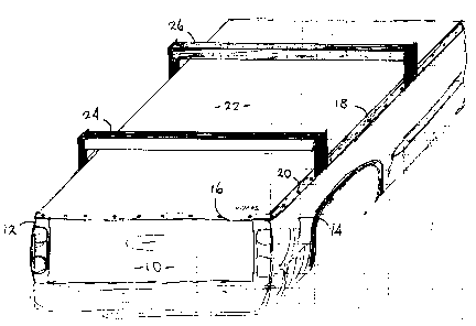
Figure 1 is a perspective view of a pair of truck carriers of the invention in
conjunction
with the open bed of a pickup truck and a tonneau cover for the open bed;
Figure 2 is an enlarged perspective view of the truck carrier and a rail for
attaching a
tonneau cover to the pickup; and
Figure 3 is an perspective view of the components of the truck carrier.
Like reference characters refer to like parts throughout the description of
the drawings.
DESCRIPTION OF THE PREFERRED EMBODIMENT
With reference to Figure 1 an open bed 10 of a pickup truck has a pair of side
walls 12,
14 and a tail gate 16. A rail 18 extends along the upper edge of side wall 14
and a like rail (not
illustrated) extends along the length of the upper edge the other side wall
12. A number of
2

CA 02358377 2001-10-10
grommets 20 are spaced along the length of the rail for receipt of dome
fasteners formed in
tonneau cover 22. Two spaced truck carriers 24, 26 are connected to the rails
and extend across
the open bed 10.
With reference to Figure 2, rail 18 has lower and upper flanges 30, 32 and a
vertical web
34 which interconnects the two flanges. An upper lip 36 extends downward from
the inner edge
of the upper flange 32 and a lower lip 38 extends upwardly from the inner edge
of the lower
flange. The lips, web and the portion of the upper and lower flanges which
extend therebetween
define a slot 40 which extends the length of the rail.
A bar 42, rectangular in section, is received in the slot and is free to slide
therein. The
two lips 36, 38 define the bar in the slot. Apertures 44 are formed in the
upper flange and
apertures 46 are formed in the upper wall of the bar. The latter apertures
open into threaded bores
which extend downwardly into the bar
With reference to Figures 2 and 3, a bracket 48 has a horizontal wall 50 and a
vertical
wall 52. Apertures 54 are formed in the horizontal wall. The spacing between
the apertures 54 is
the same as that between apertures 44 in the upper flange and between the
apertures 46 in the bar.
The bracket can be connected to the upper flange arid the bar by means of
connectors such as
screws which pass through the apertures in the horizontal wall of the bracket,
through the
apertures in the upper flange and into the threaded bores in the bar.
A number of apertures are spaced along the length of the upper flange. The
spacing

..
CA 02358377 2001-10-10
between those apertures is the same as between apertures 44 so that the
position of the bracket
can be adjusted to the position where it is most convenient. Once in that
position, the bar can be
moved until it is beneath the bracket and its apertures are in register with
those in the bracket and
upper flange. Screws can then be passed through those apertures to connect the
bracket to the
rail.
A stringer 60 has an end which is connected to the vertical wall 52 of the
bracket by
means of screws which pass through apertures 62 in the wall and into threaded
bores in the
stringer.
With reference again to Figure I, two or more truck carriers of the invention
can be used
to support a load. The load can be connected to the stringers 60 of the truck
carriers by ropes,
spring clips and the like. Once connected, the load will be above the open bed
and will occupy no
space in it.
The truck carriers do not interfere with the operation of the tonneau cover.
The cover can
be removed to gain access to the open bed and afterward can be reattached
without the necessity
of disconnecting the truck carriers from the rails or removal of the load on
the carriers.
It will be understood of course that modifications can be made in the truck
carrier
described above without departing from the scope of our invention.
4

Representative Drawing
A single figure which represents the drawing illustrating the invention.
Administrative Status

2024-08-01:As part of the Next Generation Patents (NGP) transition, the Canadian Patents Database (CPD) now contains a more detailed Event History, which replicates the Event Log of our new back-office solution.

Please note that "Inactive:" events refers to events no longer in use in our new back-office solution.

For a clearer understanding of the status of the application/patent presented on this page, the site Disclaimer , as well as the definitions for Patent , Event History , Maintenance Fee  and Payment History  should be consulted.

Event History

Description Date
Revocation of Agent Requirements Determined Compliant 2020-09-01
Inactive: IPC from MCD 2006-03-12
Application Not Reinstated by Deadline 2004-01-15
Inactive: Dead - No reply to Office letter 2004-01-15
Deemed Abandoned - Failure to Respond to Maintenance Fee Notice 2003-10-10
Deemed Abandoned - Failure to Respond to Notice Requiring a Translation 2003-05-26
Application Published (Open to Public Inspection) 2003-04-10
Inactive: Cover page published 2003-04-09
Inactive: Status info is complete as of Log entry date 2003-02-27
Inactive: Incomplete 2003-02-25
Inactive: Abandoned - No reply to Office letter 2003-01-15
Inactive: First IPC assigned 2001-12-03
Inactive: Filing certificate - No RFE (English) 2001-10-18
Inactive: Filing certificate - No RFE (English) 2001-10-17
Filing Requirements Determined Compliant 2001-10-17
Application Received - Regular National 2001-10-17

Abandonment History

Abandonment Date Reason Reinstatement Date
2003-10-10
2003-05-26

Fee History

Fee Type Anniversary Year Due Date Paid Date
Application fee - small 2001-10-10
Owners on Record

Note: Records showing the ownership history in alphabetical order.

Current Owners on Record
DONALD MARTIN
BRIAN E. MCGAULEY
JON W. MOORE
Past Owners on Record
None
Past Owners that do not appear in the "Owners on Record" listing will appear in other documentation within the application.
Documents

To view selected files, please enter reCAPTCHA code :


To view images, click a link in the Document Description column. To download the documents, select one or more checkboxes in the first column and then click the "Download Selected in PDF format (Zip Archive)" or the "Download Selected as Single PDF" button.

List of published and non-published patent-specific documents on the CPD .

If you have any difficulty accessing content, you can call the Client Service Centre at 1-866-997-1936 or send them an e-mail at CIPO Client Service Centre.


Document
Description 
Date
(yyyy-mm-dd) 
Number of pages   Size of Image (KB) 
Abstract 2003-04-10 1 2
Representative drawing 2002-03-14 1 24
Cover Page 2003-03-21 1 41
Description 2001-10-10 4 134
Claims 2001-10-10 1 42
Drawings 2001-10-10 3 111
Filing Certificate (English) 2001-10-18 1 175
Request for evidence or missing transfer 2002-10-15 1 105
Courtesy - Abandonment Letter (Office letter) 2003-02-19 1 167
Reminder of maintenance fee due 2003-06-11 1 106
Courtesy - Abandonment Letter (incomplete) 2003-06-16 1 165
Courtesy - Abandonment Letter (Maintenance Fee) 2003-12-08 1 177
Correspondence 2001-10-17 1 29
Correspondence 2003-02-14 1 18