Note: Descriptions are shown in the official language in which they were submitted.
CA 02358442 2001-06-22
NSC-H856
- 1 -
DESCRIPTION
PLATED STEEL WIRE WITH HIGH CORROSION RESISTANCE AND
EXCELLENT WORKABILITY, AND PROCESS FOR ITS MANUFACTURE
Technical Field
The present invention relates to a plated steel wire
that exhibits high corrosion resistance suitable for
steel wires for gabion, fishnets and the like that are
used in areas exposed to the outdoors.
Background Art
Commonly used plated steel wires include zinc-plated
steel wires and the more highly corrosion-resistant zinc-
aluminum alloy-plated steel wires. Zinc-aluminum alloy-
plated steel wires are generally produced by first
subjecting steel wires to a cleaning treatment such as
washing and degreasing and then to a flux treatment,
followed by either hot-dip plating of mainly zinc as the
first stage and then hot-dip plating in a Zn-Al alloy
bath containing 10% Al as the second stage, or else
direct hot-dip plating in a Zn-Al alloy bath containing
10% Al, and finally vertically drawing the wire out from
the plating bath, cooling and winding.
Such zinc-aluminum alloy-plated steel wires have
satisfactory corrosion resistance, but even higher
corrosion resistance can be achieved by methods that
increase the plating thickness. One method of
guaranteeing the prescribed plating thickness is a method
of raising the conveying speed (flux) of the steel wire
to rapidly draw out the steel wire from the plating bath,
and increasing the amount of plating alloy adhering to
the steel wire by increasing the viscosity of the hot-dip
plating alloy.
In this method, however, the high conveying speed
tends to produce an irregular plating thickness in the
cross-section perpendicular to the lengthwise direction
CA 02358442 2001-06-22
- 2 -
of the plated steel wire, and limits therefore exist for
such plating equipment. As a result, existing plating
equipment has not provided sufficient corrosion
resistance by zinc plating or by hot-dip plating with Zn-
Al alloys, and this constitutes a problem in that
expectations cannot be completely satisfied given current
expectations regarding a longer usable life for plated
steel wires.
In order to combat this problem, Japanese Unexamined
Patent Publication HEI No. 10-226865 proposes a Zn-Al-Mg
alloy plating composition with high corrosion resistance
imparted by Mg added to the plating bath, but the plating
method based on this plating composition assumes thin
layering for steel sheets, and when the method is applied
to thick plated steel wires typically used for gabion and
the like, the problem of plating layer cracking occurs
when working the plated steel wires.
Japanese Unexamined Patent Publication HEI No. 7-
207421 describes a method in which a Zn-Al-Mg alloy
plating is formed to a greater thickness, but when the
method is directly applied to plating of steel wires, the
Fe-Zn alloy layer becomes thick, leading to problems such
as cracking or peeling of the alloy layer when working
the plated steel wires.
Disclosure of the Invention
In light of the problems described above, it is an
object of the present invention to provide a plated steel
wire coated with a molten zinc alloy plating such that
the plated steel wire exhibits excellent corrosion
resistance and excellent workability that can avoid
cracking or peeling of the plating layer and/or the
plating alloy layer during working of the plated steel
wire, as well as to provide a process for its
manufacture.
The present invention has been completed as a result
of much diligent research, by the present inventors, on a
CA 02358442 2001-06-22
- 3 -
means of solving the aforementioned problems, and its
gist is as follows.
(1) A plated steel wire with high corrosion
resistance and excellent workability, the plated steel
wire being characterized in that the average composition
of the plating alloy contains, in terms of weight
percentage, Al: 4-20%, Mg: 0.8-5% and the remainder Zn,
and in that an Fe-Zn alloy layer of no greater than 20 m
thickness is present at the plating-base metal interface.
(2) A plated steel wire with high corrosion
resistance and excellent workability according to (1)
above, characterized in that the average composition of
the plating alloy also contains, in terms of weight
percentage, Si: s 2%.
(3) A plated steel wire with high corrosion
resistance and excellent workability according to (1) or
(2) above, characterized in that the average composition
of the plating alloy also contains, in terms of weight
percentage, Na: 0.001-0.1%.
(4) A plated steel wire with high corrosion
resistance and excellent workability according to any one
of (1) to (3) above, characterized in that the average
composition of the plating alloy also contains, in terms
of weight percentage, Ti: 0.01-0.1%.
(5) A plated steel wire with high corrosion
resistance and excellent workability according to any one
of (1) to (4) above, characterized in that the Fe-Zn
alloy layer contains Al: z 4%, Mg: z 1%.
(6) A plated steel wire with high corrosion
resistance and excellent workability according to any one
of (1) to (5) above, characterized in that the structure
of the plating alloy layer on the outer side of the Fe-Zn
alloy layer includes an a phase composed mainly of Al-
Zn, aP phase comprising a Zn monophase or an Mg-zn alloy
phase, and a Zn/Al/Zn-Mg three component eutectic phase.
CA 02358442 2001-06-22
- 4 -
(7) A plated steel wire with high corrosion
resistance and excellent workability according to any one
of (1) to (6) above, characterized in that the structure
of the plating alloy layer on the outer side of the Fe-Zn
alloy layer includes an a phase composed mainly of Al-
Zn, aP phase comprising a Zn monophase or an Mg-Zn alloy
phase, and a Zn/Al/Zn-Mg three component eutectic phase,
and the volume fraction of the P phase is no greater than
20%.
(8) A plated steel wire with high corrosion
resistance and excellent workability according to any one
of (1) to (5) above, characterized in that the structure
of the plating alloy layer on the outer side of the Fe-Zn
alloy layer is a dendritic structure.
(9) A plated steel wire with high corrosion
resistance and excellent workability according to any one
of (1) to (5) above, characterized in that the structure
of the plating alloy layer on the outer side of the Fe-Zn
alloy layer is a granular crystal structure.
(10) A plated steel wire with high corrosion
resistance and excellent workability according to any one
of (1) to (9) above, characterized in that the component
composition of the plated steel wire comprises, in terms
of weight percentage, C: 0.02-0.25%, Si: s 1%, Mn: s
0.6%, P: s 0.04% and S: s 0.04%.
(11) A process for the manufacture of a plated steel
wire with high corrosion resistance and excellent
workability, characterized in that the process for
manufacture of a plated steel wire comprises coating a
steel wire with a molten zinc plating composed mainly of
zinc as the first stage, and then coating it with a
molten zinc alloy plating having the average composition
specified in any one of (1) to (4) above as the second
stage.
(12) A process for manufacture of a plated steel
CA 02358442 2001-06-22
- 5 -
wire with high corrosion resistance and excellent
workability according to (11) above, characterized in
that the molten zinc plating as the first stage is a
molten zinc plating comprising, in terms of weight
percentage, Al: s 3% and Mg: s 0.5%.
(13) A process for the manufacture of a plated steel
wire with high corrosion resistance and excellent
workability according to (11) or (12) above,
characterized in that in the steps of coating with a
molten zinc plating as the first stage and coating with a
molten zinc alloy plating as the second stage, the part
of the plated steel wire drawn out from the plating bath
is purged with nitrogen gas to prevent oxidation of the
bath surface and the plated steel wire.
(14) A process for the manufacture of a plated steel
wire with high corrosion resistance and excellent
workability according to any one of (11) to (13) above,
characterized in that the molten zinc plating as the
first stage is coated for a maximum plating bath
immersion time of 20 seconds, and the molten zinc alloy
plating as the second stage is coated for a maximum
plating bath immersion time of 20 seconds.
(15) A process for the manufacture of a plated steel
wire with high corrosion resistance and excellent
workability according to any one of (11) to (14) above,
characterized in that in the steps of coating with a
molten zinc plating as the first stage and coating with a
molten zinc alloy plating as the second stage, the wire
is directly cooled by a water spray, steam or a water
flow immediately after the plated steel wire is drawn out
from the plating alloy, to harden the plating alloy.
(16) A process for the manufacture of a plated steel
wire with high corrosion resistance and excellent
workability according to any one of (11) to (15) above,
characterized in that in the steps of coating with a
molten zinc plating as the first stage and coating with a
molten zinc alloy plating as the second stage, the
CA 02358442 2008-04-17
6
initial cooling temperature for cooling of the plated steel
wire is in a range from the melting point of the plating
alloy to 20 C above the melting point.
(17) A process for the manufacture of a plated steel
wire with high corrosion resistance and excellent
workability according to any one of (11) to (16) above,
characterized in that the component composition of the
plated steel wire comprises, in terms of weight
percentage, C: 0.02-0.25%, Si: S 1%, Mn: <- 0.6%, P:!90.04%
and S: s 0.04%-.
The present invention relates to a plated steel wire
with high corrosion resistance and excellent workability,
characterized in that an average composition of a plating
alloy contains, in terms of weight percentage, Al: 10 - 20%,
Mg: 0.8 - 5% and a remainder Zn, in that an Fe-Zn alloy
layer, containing Al: - 4% to 30wt%, Mg: 1% to 5.6wtt, of
at most 20 pm thickness is present at a plating-base metal
interface, said Fe-Zn alloy layer being formed by plating
said plating alloy on a Zn-plated layer containing Al S 3wtt
and Mg S 0.5wt%, remainder being Zn and in that a structure
of a plating alloy layer on an outer side of said Fe-Zn
alloy layer includes an phase composed of Al-Zn, a R
phase comprising a Zn monophase, a Mg-Zn alloy phase and a
Zn/Al/Zn-Mg three component eutectic phase.
Brief Description of the Drawings
Fig. 1 is a graph showing the relationship between Mg
addition and an index of the amount of dross
production generated on the plating bath surface, for a
case in which Mg is added to a Zn-10% Al alloy.
Fig. 2 is a graph showing the relationship between the
alloy layer thickness and the number of cracks in a winding
test, for a case of Zn-10% Al-1% Mg alloy plating.
CA 02358442 2008-04-17
6a
Fig. 3 is a graph comparing surface cracking (number of
cracks) in a winding test with and without isolation from
air, for a plated steel wire having a Zn-10% A1-3%- Mg
plating alloy composition.
Fig. 4 is a graph showing the relationship between
the plating bath immersion time and the Fe-Zn alloy layer
thickness.
Best Mode for Carrying Out the Invention
The plated steel wire of the invention will first be
explained in detail.
The plating alloy in the plated steel wire of the
invention has an average composition, in terms of weight
percentage, of Al: 4-20%, Mg: 0.8-5g and the remainder
Zn.
Al has an effect of increasing the corrosion
CA 02358442 2001-06-22
- 7 -
resistance, but when added at less than 4% it provides no
effect and the antioxidizing effect of Mg in the plating
bath cannot be obtained. When Al is added at greater
than 20%, the resulting plating alloy is hard and
fragile, which makes it impossible to accomplish working.
The range for Al in the plating alloy is therefore 4-20%.
When plating a steel wire, this range is preferably 9-14%
in order to achieve greater thickness. A stable plating
layer can be obtained when the Al content is within this
range.
Mg produces a uniform plating corrosion product, and
corrosion products containing Mg act to prevent further
corrosion. Mg therefore has an effect of improving the
corrosion resistance of the plating alloy. When added at
less than 0.8%, however, no effect of improved corrosion
resistance can be achieved. On the other hand, if added
at more than 5%, the plating bath surface tends to
undergo oxidation and generate large amounts of dross,
thus hampering operation.
Fig. 1 is a graph showing the relationship between
Mg addition and an index of the amount of dross
production generated on the plating bath surface, for a
case in which Mg is added to a Zn-10% Al alloy. The
conditions are the same other than the amount of Mg
added. When the amount of added Mg exceeds 5%, a larger
amount of dross is produced, thus increasing the
frequency at which the dross must be removed and
hampering operation. Based on this result, the range for
the amount of Mg has been determined to be 0.8-5%, in
order to ensure both corrosion resistance and low dross
production.
An alloy layer composed mainly of Fe-Zn is formed at
the plating-ground iron interface, and when this alloy
layer is thick the alloy layer may crack, tending to
result in cracking at the interface between the alloy
layer and the base metal, or at the interface between the
alloy layer and the plating.
CA 02358442 2001-06-22
- 8 -
Fig. 2 is a graph showing the relationship between
the alloy layer thickness and the number of cracks in a
winding test, for a case of Zn-10% Al-1% Mg alloy
plating. This graph shows that cracking increases when
the thickness of the plating alloy layer is greater than
20 [tm, such that the plating cannot withstand practical
use. Thus, since 20 m is the upper limit for thickness
of a plating alloy layer that does not impair the
workability, the thickness of the Fe-Zn alloy layer is
limited to 20 m. The alloy layer is preferably of a
lower thickness since its corrosion resistance is
inferior to conventional plating layers, and it is even
more preferably limited to no greater than 10 m.
It is effective to add Si to the plating layer in
order to further increase the corrosion resistance.
Addition of Si is more effective with a greater amount of
Al addition. In the plated steel wire of the invention,
the maximum amount of Si that gives an effect is 2% with
an Al addition of 20% of the maximum, and therefore the
range for Si is limited to no greater than 2%.
Dross will be produced on the plating bath surface
when performing the plating, and it is effective to add a
trace amount of Na to inhibit this dross production.
Inhibiting the dross production can provide the effect of
an improved plating surface and a greater plating alloy
yield. A trace amount of Na is therefore added to the
plating alloy, but if it exceeds 0.1% the Na will undergo
oxidation, and therefore the range for the amount of Na
is limited to 0.001-0.1%. Addition of Ti also has the
effect of inhibiting dross production, and the range for
effective addition of Ti is 0.01-0.1%.
In addition to Si, Na and Ti mentioned above,
addition of antimony, misch metals and the like also
provides the effect of improving the plating surface
condition.
In the plated steel wire described to this point,
CA 02358442 2001-06-22
- 9 -
the corrosion resistance is improved by including Al:
z
4% and Mg: Z 1% in the Fe-Zn alloy layer present at the
plating-ground iron interface. Since no effect of
improved corrosion resistance is obtained when the Al in
the aforementioned alloy layer is less than 4%, the range
for the Al content is 4% or greater.
Also, the presence of Mg produces a uniform
corrosion product and improves the corrosion resistance,
and since no effect can be obtained at less than 1%, the
range for the Mg content is 1% or greater.
Because the plated steel wire of the invention
contains Al and Mg as components, cooling after the
plating can form an a phase composed mainly of Al-Zn, a
phase comprising a Zn monophase or an Mg-Zn alloy phase,
and a Zn/Al/Zn-Mg three component eutectic phase,
copresent in the plating alloy layer on the outer side of
the alloy layer present at the plating-ground iron
interface.
Of these, the presence of the Zn/Al/Zn-Mg three
component eutectic phase provides a uniform corrosion
product and an effect of inhibiting further corrosion due
to the uniform corrosion product. The p phase has
inferior corrosion resistance compared to the other
phases, and thus tends to undergo local corrosion. If
the volume fraction of the P phase is over 20% the
corrosion resistance tends to be lower, and therefore its
volume fraction is limited to 20%.
When the plated steel wire is drastically cooled by
water cooling, the structure of the plating alloy layer
on the outer side of the alloy layer composed mainly of
Fe-Zn present at the plating-ground iron interface can be
converted to a dendritic structure. When a dendritic
structure is formed, each of the structures produced in
the plating become intricate, and the corrosion
resistance is thus improved.
CA 02358442 2001-06-22
- 10 -
When the plated steel wire is gently cooled by water
cooling, the structure of the plating alloy layer on the
outer side of the alloy layer composed mainly of Fe-Zn
present at the plating-ground iron interface can be
converted to a granular crystal structure. When a
granular crystal structure is formed, each of the
structures produced in the plating become granular, and
this inhibits propagation of cracks to thus improve the
workability.
The process used for manufacture of the plated steel
wire of the invention is a two-stage plating process. By
coating a molten zinc plating composed mainly of zinc to
form an Fe-Zn alloy layer as the first stage and then
coating a molten zinc alloy plating with the average
composition specified according to the invention as the
second stage, it is possible to efficiently obtain a
plated steel wire according to the invention. The molten
zinc used for the molten zinc plating of the first stage
may be a molten zinc alloy comprising, in terms of weight
percentage, Al: s 3% and Mg: s 0.5%. When an Fe-Zn alloy
layer is obtained by molten zinc plating in the first
stage, inclusion of Al and Mg in the Fe-Zn alloy layer
has the effect of allowing easier diffusion of Al and Mg
in the plating alloy layer.
In the process for manufacture of the plated steel
wire of the invention, enhanced workability can be
achieved if the part of the plated steel wire drawn out
from the plating bath is purged with nitrogen gas to
prevent oxidation of the bath surface and the plated
steel wire. When oxides are produced on the plating
surface after plating or when produced oxides adhere to
the bath surface, the plating sometimes suffers cracking
around the oxides as nuclei during working of the plated
steel wire. For this reason, it is important to prevent
oxidation of the drawn out portion.
Fig. 3 is a graph comparing surface cracking (number
of cracks) in a winding test with and without isolation
CA 02358442 2001-06-22
- 11 -
from air, for a plated steel wire having a Zn-10% Al-3%
Mg plating alloy composition. Without isolation from
air, the number of cracks produced on the surface exceeds
the maximum allowable number. while an inert gas such as
argon or helium can be used instead of nitrogen in order
to prevent oxidation, nitrogen is superior in terms of
cost.
When a plated steel wire according to the invention
is obtained by the two-stage process, suitable growth of
the plating alloy can only be achieved if the molten zinc
plating composed mainly of zinc as the first stage is
coated for a maximum plating bath immersion time of 20
seconds, and the molten zinc alloy plating as the second
stage is coated for a maximum plating bath immersion time
of 20 seconds. When the plating is carried out for a
longer time, the thickness of the alloy layer is
increased beyond 20 m; consequently, the molten plating
composed mainly of zinc as the first stage is coated for
a maximum plating bath immersion time of 20 seconds, and
the molten zinc alloy plating as the second stage is
coated for a maximum plating bath immersion time of 20
seconds.
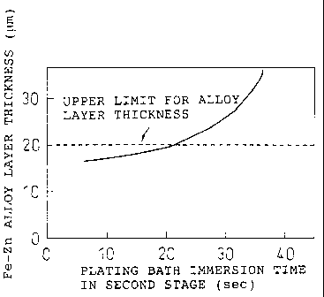
Fig. 4 is a graph showing the relationship between
the plating bath immersion time and the Fe-Zn alloy layer
thickness, for a case in which molten zinc plating
(immersion time: 20 seconds) has been carried out in the
first stage to form an Fe-Zn alloy layer with a thickness
of 15 m, and the plated wire is coated with a molten
zinc alloy plating using a Zn-10% Al-1% Mg bath
composition (second stage). This graph shows that in the
molten zinc alloy plating of the second stage, the
thickness of the alloy layer undergoes little growth with
a plating alloy bath immersion time of up to 20 seconds,
and the alloy layer thickness is no greater than 20 ~im.
If cooling is carried out rapidly while the plating
alloy of the plated steel wire is in a molten state after
CA 02358442 2001-06-22
- 12 -
plating it is possible to harden each phase without
growth, thus resulting in a superfine plating structure.
If the cooling is carried out in a more drastic manner,
dendrites form as the hardened structure of the plating
alloy. The process may entail direct cooling by a water
spray, steam or a water flow immediately after the plated
steel wire is drawn out from the plating bath, to harden
the plating alloy.
For cooling of the plated steel wire, it is
necessary to initiate the cooling while the plating is
still in a molten state. If hardening occurs as a result
of air cooling, each of the phases will grow during the
hardening to form a coarse structure. The initial
cooling temperature must therefore be above the melting
point of the plating alloy. Also, contact of the cooling
water with the high-temperature molten plating with low
viscosity will roughen the plating surface, and therefore
the upper limit for the initial cooling temperature is
C above the melting point of the plating alloy.
20 The component composition of the plated steel wire
comprises, in terms of weight percentage, C: 0.02-0.25%,
Si: s 1%, Mn: s 0.6%, P: s 0.04% and S: s 0.04%.
C is the element that determines the strength of the
steel, and in order to achieve the strength of an
ordinary plated steel wire it must be added to at least
0.02%. On the other hand, if added at greater than 0.25%
the strength will be too high, such that when it is used
in a gabion or the like it will not be bendable when
worked by hand; the upper limit is therefore 0.25%.
Si has the effect of improving the plating adhesion
while also increasing the strength. The strength becomes
too high if the Si content is greater than 1%, and
therefore the upper limit is 1%.
Mn has the effect of increasing the toughness of the
steel while also increasing the strength. The strength
becomes too high if the Mn content is greater than 0.6%,
and therefore the upper limit is 0.6%.
CA 02358442 2001-06-22
- 13 -
P and S can cause stiffening of the steel, and both
are therefore limited to no greater than 0.04%.
The surface of a molten zinc-plated steel wire or a
molten zinc alloy-plated steel wire obtained according to
the invention may be coated with at least one type of
polymer compound selected from the group consisting of
vinyl chloride, polyethylene, polyurethane and fluorine
resins, in order to further enhance the corrosion
resistance.
Examples
4-mm diameter steel wires, each comprising a pure Zn
plating coated on the surface of a,7IS G 3505 SWRM6 steel
wire material, were coated with Zn-A1-Mg-based zinc alloy
platings under the conditions shown in Table 1, and
evaluated. For comparison, wires with different plating
compositions, Fe-Zn alloy layer structures and plating
structures were evaluated in the same manner.
The plating structure of each was observed by EPMA
after polishing the cross-section of the plated steel
wire. Analysis of the composition of the alloy layer was
carried out by quantitative analysis with a beam diameter
of 2 m.
The corrosion resistance was evaluated as the
corrosion loss per unit area due to corrosion of the
plating, based on the difference in weight before and
after a continuous salt spray test for 250 hours. A
measurement of 20 g/mz or less was judged as acceptable
for the test.
The workability was evaluated by winding the
manufactured plated steel wire onto a 6 mm-diameter steel
wire six times, visually observing its surface, and
determining the presence or absence of cracks. After
evaluation of the cracks, cellophane tape was pressed
onto the sample and then peeled off, and the presence or
absence of peeling of the plating was observed and
evaluated. A limit of one crack and no peeling was
CA 02358442 2001-06-22
- 14 -
judged as acceptable for this test.
Table 1 shows the relationship between the
composition and thickness of the plating structure and
alloy layer, the thickness, composition and (3 phase
volume fraction of the plating outer layer, the corrosion
resistance (corrosion loss), the workability (evaluation
of the winding test) and the plating bath dross
production.
The invention examples all exhibited satisfactory
corrosion resistance and workability, and the dross
production was also minimal. Comparative Examples 1-5
had plating alloy component compositions that were
outside of the ranges of the component compositions
specified by the present invention. Comparative Examples
1 and 2 had Mg or Al contents below the lower limits
specified by the invention, and the corrosion resistance
was inferior. Comparative Examples 3-5 had Mg or Al
contents above the upper limits specified by the
invention, and the workability was inferior and the
plating bath dross production was greater, creating a
hindrance to operation. Comparative Examples 6 and 7 had
plating alloy layer thicknesses that were outside of the
range specified by the invention, and this resulted in
inferior workability. Comparative Examples 8-10 had (3
phases in the plating structure that were outside of the
range specified by the invention, and the corrosion
resistance was inferior.
Table 2 shows the relationship between the plating
immersion time, the cooling method and initial cooling
temperature for the molten zinc alloy plating in the
second stage, the corrosion resistance and the
workability, for a composition of Zn-10% Al-3% Mg. The
samples whose plating conditions were within the ranges
specified by the invention exhibited satisfactory
results.
CA 02358442 2001-06-22
- 15 -
U) c
"o~
y 0 0 0 0 0 0 0 0 0 0 0 0 0 0 0 0 0 0 x x x 0 0 0 0 0
41 o
ro u
.Aa
------- -------------------------------------------------------------
41 ~
0 0 0 0 0 0 0 0 0 0 0 0 0 0 0 0 0 0 x x x x x 0 0 0
a
--------- --------------------------------------------------------------------
--------------------------------------------
0 0 0 0 0 0 0 0 0 0 0 0 0 0 0 0 0 0 x x x x x 0 0 0
U
C
0
H N. u'1 N l0 N m
y 01 a 0 v f`'1 N r-1 (+1 .ti f'1 v v N M v 10 C= M v v Ol Ul N v M v w f`-I
0 0 \
N^~ X X X X X
0
U
0 O
-4 M "O Ill
4J 01 m W t- M M.-1 N N f~1 OI 01 m O~ ~O [- N N(`'1
Q) U ~-i rl ri ri r7 ri rl I I ~ I I I ei .-i r-1 .-1 rl I rl ~
ro u X X X
x w
VI tll (A U) tl) fA 71 01 Ol N Ol 0 tll Oi W tll W tl) Vi
ri '=I 1 .-I .-i 'i .i .-I .-i
ro ro ro ro ro ro ro ro ro ro ro ro ro ro ro ro ro (a
ro
u 4J 4.1 11 N yJ }I .yJ }7 41 4.) õ 4J y! 4-1 YI õ yõ 11
y Vi Ul 07 pl Vl N N 07 Oi fq Ul tli fq tll tll 4`~1 41 y^~ U^~l
~ ~ ~ 41 ~ ~ ~ ~ ~ ~ ~ ~ ~ 41 ~ 1=I N
U U U U U U U U U U U U U U U U U U U
{.r U u u U u u u u u u u u u u U u u u u
N '.d '.i '.i -4 'H =rl =.i .1 ='I =.i =.i .=I =.i ..i .I ==i =d =.=i .1
yl 41 4.1 1J JJ 4.1 1J lJ JJ 11 11 .u jJ yu 11 4.1 JJ yJ 1J lJ
p a u u o o U o 0 0 0 o u o 0 o u o o u o 0 0 o u o u u
0 u UI UI N Cl N m Ol G) -i -H UI =H GI i .~ CI O) Gl CI 0 -14 ~a m GI N
u aJ sJ u,J u r, + iJ u,J aJ +J +J .u iJ 4+ aJ 4J 4J ,J u u y a+ 41
bl l! ~ 7 :! 7 ~ ~ ~ ~ =.~ .i U =.i :I =.i -.i 0 7 0 :3 :3 -.i :3 =.i :1 U :1
~ 0 Ua N W N N W W N d H N N yd Gl N d N W W N CI C1
~ ~ ++ + .u +~ ~ .~ aJ a~ Oa Oa y 0 a Oa ~ ,J y u ~ a0 u Oa ~ .u .u
(d +J a a a G a e a a d v a a~ 0 v a~ a c c a a a wr c a
.+ tn a) al al al al w w a~ v v al v aD v b w d 0 a) a~ v al v w ar w
q C q 0 q q q C 0 G 0 C Q q C q q C q
0 0 O 0 0 0 0 0 0 0 0 0 0 0 0 0 0 0 0
R ~ ~ ~~~t 101 p R
O 0 O o 0 0 0 O 0 0 0 O 0 0 0 0 0 0 O
U U U U U U U U U U U U U U U U U U U
I I I I I I I 1 1 I I I I I I 1 I I I
M M f+1 M M f`1 f+1 M fn M M M M M M M M P'1 M
\ \ \ \ \ \ \ \ \ \ \ \ \ \ \ \ \ \ \
~c..'`.cr~ ^~ ~ C= CC,~'.
\ \ \ \ \ \ \ \ \ ~ \ \ \ \ \ \ \ \ \
u v C C CS CS 0 ZS 0 C d C ~ C ~. CS ~ C
X N
U N 6 O r-i N 01 Ill m M N ri r=I 01 .-4 m m . - 1 4 O O=i O O 1(1 O m O 0
~ 0 3 M v W In C- v ul N N ri 1!1 M v N M ri N -I .-1 (+1 ri 'i tO r-1 N
F
N x di q m M.i t0 N m M r 0 N 0 ~D M mID O Ifl m f~1 N m.1 0 m r 11
01 .~ a ==1 .-1 .-1 .-1 .-1 .-I -I ~-I -1 -4 .i -1 -I N 'i e-1 -1 .-I .-1 M N
.-I .-i N
m C ~ X X
1.4
l 1O N 1 M1O v In v m 10 m~O m l0 .i 1[1 1D M 10 N.-i .-1 m
0 ~ do ~ . . . . . . . . . . . . . . . . . . . . . . ~
14 ("1 .-1 .-1 v r=1 M'-1 M M.i .=i M u'1 v N rl Oi u1 M L!1 rl Mi N M
r=i
O r= N N M.-i vtO N v M~==1 11 w m O mw v M.4 1=1 kO N M Ifl
N N N N N N N N N N N N N N N fn .-1 -4 N N N N N H .-1 -1
N O
F a o 0
0 0 0
.H
+1 m rn
.H ~ z o 0
0 0
o M m
U .,~
~ rn 'i O
N W OI O 0~ ri ~-1 01 N N r=1 If1 v M O M~-1 O O O OI M O~ ri N
f'1 ri O r=i N.=I M N~==I .=i M v v N ri O.=i 0 MO O N O N M
'-I
a
rj r v 41 0~-1 O oH .4 O.=i O o m V l0 Oi lf1 N r If7 m r-I O m M o
.-1 .-4 r=1 rl .=1 H r=1 ri r=I '=1 .-I H .-1 ==1 N ri .-i r=1 r-1 .4
.i N f'1 v t!1 kO l- m 01 O r=1 N M v U1 'o H N f"1 v l(1 kD t'- m m O
.-1 rl =I H r-1 r-4 r-I .q
H W V X
CA 02358442 2001-06-22
- 16 -
Table 2
Plating Molten zinc alloy plating in second stage Corro- Wind-
immersion time sion ing
(sec) loss test
First Second Cooling method Initial cooling time
stage stage
1 15 18 water spray melting point + 1 C 0 0
2 11 19 steam spray melting point + 1 C 0 0
3 19 11 direct water flow melting point + 10`C 0 0
4 18 10 steam spray melting point + 10'C 0 0
Inven-
t 5 8 19 water spray melting point + 11"C 0 0
ion
Exs. 6 6 18 direct water flow melting point + 11 C 0 0
7 15 10 steam spray melting point + 19 C 0 0
8 18 10 direct water flow melting point + 19 C 0 0
9 9 19 direct water flow melting point + 19 C 0 0
18 18 steam atomizing melting point + 19`C 0 0
1 15 25 direct water flow melting point + 10 C 0 x
2 28 10 steam spray melting point + 11'C 0 x
3 16 12 cooling in air no cooling x x
Comp. 4 13 16 cooling in air no cooling x x
Exs. 5 12 15 water spray melting point + 35'C x 0
6 15 12 steam spray melting point + 28'C x 0
7 16 11 water spray melting point - 10 C x 0
8 18 9 steam spray melting point - 10'C x 0
CA 02358442 2001-06-22
- 17 -
Industrial Applicability
As explained above, according to the present
invention, it is possible to obtain zinc alloy-plated
steel wires with high corrosion resistance and excellent
workability.
Incidentally, although the present invention relates
particularly to wire materials, it is a technique that
may be adequately applied to steel pipes and steel
structures as well, and it is therefore expected to offer
a major contribution to industrial technology.