Language selection

Search

Patent 2358869 Summary

Third-party information liability

Some of the information on this Web page has been provided by external sources. The Government of Canada is not responsible for the accuracy, reliability or currency of the information supplied by external sources. Users wishing to rely upon this information should consult directly with the source of the information. Content provided by external sources is not subject to official languages, privacy and accessibility requirements.

Claims and Abstract availability

Any discrepancies in the text and image of the Claims and Abstract are due to differing posting times. Text of the Claims and Abstract are posted:

  • At the time the application is open to public inspection;
  • At the time of issue of the patent (grant).
(12) Patent Application: (11) CA 2358869
(54) English Title: WORKING METHOD AND INSTALLATION FOR THE FLEXIBLE AND ECONOMICAL PICKLING AND COLD-ROLLING OF METAL STRIPS
(54) French Title: PROCEDE DE TRAVAIL ET INSTALLATION POUR LE DECAPAGE ET LE LAMINAGE A FROID SOUPLE ET ECONOMIQUE DE FEUILLARDS METALLIQUES
Status: Deemed Abandoned and Beyond the Period of Reinstatement - Pending Response to Notice of Disregarded Communication
Bibliographic Data
(51) International Patent Classification (IPC):
  • B21B 1/28 (2006.01)
  • B21B 1/36 (2006.01)
  • B21B 15/00 (2006.01)
  • B21B 45/06 (2006.01)
  • B21C 47/24 (2006.01)
(72) Inventors :
  • HANSEN, MANFRED (Germany)
(73) Owners :
  • SMS DEMAG AG
(71) Applicants :
  • SMS DEMAG AG (Germany)
(74) Agent: SMART & BIGGAR LP
(74) Associate agent:
(45) Issued:
(86) PCT Filing Date: 2000-01-18
(87) Open to Public Inspection: 2000-08-10
Availability of licence: N/A
Dedicated to the Public: N/A
(25) Language of filing: English

Patent Cooperation Treaty (PCT): Yes
(86) PCT Filing Number: PCT/DE2000/000186
(87) International Publication Number: DE2000000186
(85) National Entry: 2001-07-19

(30) Application Priority Data:
Application No. Country/Territory Date
199 05 286.7 (Germany) 1999-02-03

Abstracts

English Abstract


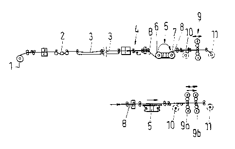
The invention relates to a working method and an installation for the pickling
and cold-rolling of metal strips. Said installation is comprised of a metal
pickling device, of a winder arrangement provided on the winding side of the
metal pickling device, and of a cold rolling mill which are all arranged in a
line. The invention is characterized by the alternative sequence of subsequent
working steps: a) The strip exiting the metal pickling device, for a first
reduction pass, is introduced into the cold rolling mill while bypassing the
winder arrangement and is rolled out in a plurality of shaping passes or; b)
the strip exiting the metal pickling device is wound into a coil on the winder
arrangement and, after being unwound, is introduced into the cold rolling mill
and is rolled in a plurality of shaping passes or; c) the strip exiting the
metal pickling device is wound as a hot-rolled strip on the winder arrangement
in order to produce a finished strip or; d) prepickled hot-rolled strips are
fed to the winder arrangement, are introduced into the cold rolling mill when
unwound, and are rolled in a plurality of shaping passes.


French Abstract

L'invention concerne un procédé de travail et une installation pour le décapage et le laminage à froid de feuillards métalliques, ladite installation étant constituée d'un dispositif de décapage de métal, d'un ensemble d'enroulement et d'un laminoir à froid. Le procédé présenté se caractérise par trois séquences possibles d'étapes successives: a) le feuillard quittant le dispositif de décapage de métal est, en évitant l'ensemble d'enroulement, introduit dans le laminoir à froid, pour y subir une première passe de laminage, puis laminé en plusieurs passes de déformation; ou bien b) le feuillard quittant le dispositif de décapage de métal est enroulé sur l'ensemble d'enroulement pour former une bobine, et après passage à la position déroulée, est introduit dans le laminoir à froid et laminé en plusieurs passes de déformation; ou bien c) le feuillard quittant le dispositif de décapage de métal est enroulé, à l'état chaud, sur le dispositif d'enroulement pour former un feuillard fini; ou bien encore d) les feuillards chauds prédécapés sont conduits à l'ensemble d'enroulement et, en position déroulée, introduits dans le laminoir à froid et laminés en plusieurs passes de déformation.

Claims

Note: Claims are shown in the official language in which they were submitted.


CLAIM(S)
1. Installation for the flexible and economical pickling and
cold- rolling of metal strips, especially in small-to-medium
production volumes, consisting of an in-line arrangement of a
metal pickler, a reeling arrangement on the coiling side of the
working method according to one of Claims 1-4, characterized in
that the reeling arrangement is designed as a horizontal or
vertical reverse coiler (5) with two separate drive units, one
for each reel mandrel (a coiling reel mandrel (6) and an
uncoiling reel mandrel (7)), which are preferably disconnected
when the reel is reversed, and in that the reel mandrel (7)) are
mounted in their housings with the freedom to move in the axial
directions.
2. Installation according to Claim 1, characterized in that
the reversing mill (9) is designed as a 2-strand or 3-stand tandem
stand group (stands (9a, 9b)) with reversing reels (10, 11) at
each end of the tandem stand group.
3. Installation according to one of the preceding claims,
characterized in that reversing rolling mill (9) is equipped with
6-high stands (9a, 9b)
4. Working method for the flexible and economical pickling
and cold- rolling of metal strip, especially in small-to-medium
production volumes, on an installation according to the preceding
claims, characterized by the following alternative sequences of
work steps:
(a) the strip leaving the metal pickler bypasses the reeling
arrangement and is introduced into the cold-rolling mill for a
first reduction pass and rolled out over the course of several
deformation passes;
or
(b) the strip leaving the metal pickler is wound on the
reeling arrangement into a coil; after the coil is switched to
the uncoiling position, the strip is fed into the cold-rolling
mill and rolled out over the course of several deformation
passes;
or
(c) the strip leaving the metal pickler is wound as hot-
rolled strip on the reeling arrangement to obtain the finished
strip; or
6

(d) pre-pickled, hot-rolled strips are sent to the reeling
arrangement and then uncoiled from the uncoiler into the cold-
rolling mill and rolled in several deformation passes.
5. Working method according to Claim 4, characterized in
that the cold- rolling is accomplished on a reversing mill, to
which the strip, produced according to work step (a), (b), or
(d), is introduced and rolled out in several reversing passes,
where the strip, after one or more reversing passes, is wound on
at least one of the reversing reels, one of which is installed at
each end the reversing mill.
6. Working method according to Claim 4, characterized in
that the strip produced according to work step (a), (b), or (d)
is cold-rolled on a 2-stand or 3-stand tandem line, on which the
strip is rolled out in a single pass.
7. Working method according to Claim 4, characterized in
that the strip produced according to work step (a), (b), or (d)
is cold-rolled on a 2-stand or 3-stand tandem line, where the
strip is wound after one or more reversing passes on at least one
of the reversing reels, one of which is installed at each end of
the tandem line.
7

Description

Note: Descriptions are shown in the official language in which they were submitted.


CA 02358869 2001-07-19
WORKING METHOD AND INSTALLATION FOR THE FLEXIBLE AND~ECONOMICAL
PICKLING AND COLD-ROLLING OF METAL STRIPS
S P E C I F I C A T I O N
The invention pertains to a working method and to an
installation for the flexible and economical pickling and cold-
rolling of metal strip, especially in small-to-medium production
volumes on an installation consisting of an in- line arrangement
of a metal pickler, a reeling arrangement on the coiling side of
the metal pickler, and a cold-rolling mill.
It is known that metal picklers and rolling mills can be
connected and operated as so-called "endless rolling mills".
These mill layouts offer many advantages because of the
elimination of the discontinuous threading operation, and they
usually provide very high production rates per unit time. They
require such a large investment, however, that many operators of
installations for smaller production volumes continue to invest
in separate metal picklers and rolling mills.
In order to achieve higher production rates in spite of this
difficulty, multi-stand reversing mills and/or the creation of
extremely large coils only for the section between the metal
pickler and the mill have been proposed, these large coils being
uncoiled and cut downline from the mill so that they are small
enough to be transported and subjected to further processing (EP
0,724,919 A2). Installations of this type require extremely
large custom equipment for the coiling machines, which appears to
cast doubt on the cost advantages.
The task of the present invention is to create a process and
an installation by means of which an extremely flexible pickling-
and-rolling operation for small-to-medium production volumes can
be achieved economically without the need to add or omit any
system components for operational reasons, with minimal
1

f
, CA 02358869 2001-07-19
investment and personnel costs, and with the use of. conventional
coil sizes and'machine dimensions.
To accomplish this task with the use of a given installation
consisting of an in-line arrangement of a metal pickler, a
reeling arrangement on the coiling side of the metal pickier, and
a cold-rolling mill, a working method is proposed which is
characterized by various alternative sequences of work steps:
(a) the strip leaving the metal pickier bypasses the reeling
arrangement and is introduced into the cold-rolling mill for a
first reduction pass and rolled out over the course of several
deformation passes;
or
(b) the strip leaving the metal pickier is wound on the
reeling arrangement into a coil; after the coil is switched to
the uncoiling position, the strip is fed into the cold-rolling
mill and rolled out over the course of several deformation
passes;
or
(c) the strip leaving the metal pickier is wound as hot-
rolled strip on the reeling arrangement to obtain the finished
strip; or
(d) pre-pickled, hot-rolled strips are sent to the reeling
arrangement and then uncoiled from the uncoiler into the cold-
rolling mill and rolled in several deformation passes.
In the solution proposed according to the invention, a so-
called "partial coupling" of a metal pickier and rolling mill is
set up in a consistent manner so that all three operating modes,
i.e., endless rolling, partial coupling, and discontinuous
operation, can be run equally well on one and the same
installation.
In accordance with an embodiment of the invention, it is
preferably provided that the cold-rolling is done on a reversing
mill into which the strip produced according to work step (a),
2

CA 02358869 2001-07-19
(b), or (c) is introduced and rolled out over the course of
several reversing passes, where the strip, after one or more
reversing passes, is wound on at least one of the reversing
reels, one of which is installed at each end of the reversing
mill.
According to another feature of the invention, it is also an
effective option to cold-roll the strip produced according to
work step (a) , (b) , or (d) on a 2-stand or 3-stand tandem line,
on which the strip is rolled out in a single pass, or, in
accordance with another alternative, to wind the strip after one
or more reversing passes on at least one of the two reversing
reels, one of which is installed at each end of the tandem line.
An installation for the flexible and economical pickling and
cold-rolling of metal strip according to the work steps defined
according to the invention is characterized by a reeling
arrangement, which is designed as a horizontal or vertical
reverse toiler with two separate drive units, one for each reel
mandrel, these drives preferably being disconnected when the
reeling arrangement is reversed. Layouts of this type are known
in principle; only its inclusion in the complete installation
according to the invention for performing all of the work steps
in question is claimed by the present invention.
It is favorable for the reel mandrels of the reverse toiler
to be free to move in the axial direction in their housings, so
that, as the coil is being fed out from the reel mandrel
downstream from the metal pickler, it can be kept centered as it
enters the rolling mill.
The reversing mill can be designed as a conventional
reversing stand or as a 2-stand or 3-stand tandem group with a
reversing reel installed at each end of the tandem group. As
soon as the reversing reel of the reversing stand has accepted
the strip, the reel mandrel of the reverse toiler is free again
to form a new coil from the strip coming from the metal pickler.
3

CA 02358869 2001-07-19
Especially when high pass reductions are required, e.g., when
rolling is performed in only a single pass, it is favorable for
the cold-rolling mill to be equipped with 6-high stands, which
allow a greater degree of deformation.
An installation according to the invention for implementing
the working method is extremely flexible, needs only a minimum of
operating personnel, requires little room, has low investment
costs, and shows its greatest economy in conjunction with the use
of the thin, hot-rolled strip which is being produced
increasingly in thin slab plants and strip-casting plants.
The invention is explained in greater detail below on the
basis of a schematic diagram of an installation according to the
invention.
The strip B, which has been uncoiled from an uncoiler reel 1,
is first subjected to conventional preparation and then sent over
the set of drive rolls 2 of the metal pickler 3, designed as a
push pickler, to processing. The metal pickler 3 is equipped on
the delivery side, downstream from the conventional auxiliary
devices 4 such as scrubbers, scrap shears, and parting shears,
with a horizontal reverse coiler 5, onto which the strip B
leaving the metal pickler is coiled. The reverse coiler 5 has a
coiling reel mandrel 6 and an uncoiling reel mandrel 7 with
separate drives; that is, each reel mandrel has its own drive
unit, which is preferably disconnected when the reel is reversed.
The uncoiling reel mandrel and the coiling reel mandrel are
installed in the housing in such a way that they can move in the
axial direction, so that the uncoiling reel mandrel 7 facing away
from the metal pickler 3 can feed out the coil 8, which has been
coiled up downstream from the metal pickler 3, in a controlled
manner so that it is kept centered as it enters the following
reversing mill 9.
The reversing mill 9 consists of a traditional reversing
stand, which, after the first reduction pass, sends the coil 8 to
4

~
CA 02358869 2001-07-19
the reversing reel 10. The uncoiling reel mandrel 7 of the
reverse toiler ~ 5 is then free to switch places with the coiling
reel mandrel 6 and can accept a new strip coming from the metal
pickler 3.
The reversing stand 9, as shown in the lower part of the
drawing, can also be a 2-stand or 3-stand tandem train with
stands 9a, 9b. These are preferably designed as 6-high systems
(in which the relatively small work rolls are supported by
intermediate and backup rolls) for high reductions (more than 50%
in the first stand), so that some of the pickled strips B can be
rolled in a single pass. In this case, as illustrated, the strip
can simply travel over the top of the reverse toiler 5 in so-
called endless operating mode.
If several passes are required in the reversing mill, the
metal pickler 3 can easily prepare so-called P & O coils, which
are not cold-rolled, during the associated waiting periods. The
strip B in this case is coiled downstream from the metal pickler
3 on the coiling reel mandrel 6 of the reverse toiler 5 and
delivered as finished product. P & O coils of this type can, of
course, also be pickled during long breaks in the operation of
the reversing mill 9, such as those which occur when the backup
rolls are being replaced.
The flexibility of the installation also means that coils 8
which have already been pickled and held in storage can be rolled
out in the reversing mill 9 during the times that the metal
pickler 3 is out of service. These coils 8 are supplied to the
uncoiling reel mandrel 7 of the reverse toiler 5, where they are
uncoiled and sent to the reversing mill 9.

Representative Drawing
A single figure which represents the drawing illustrating the invention.
Administrative Status

2024-08-01:As part of the Next Generation Patents (NGP) transition, the Canadian Patents Database (CPD) now contains a more detailed Event History, which replicates the Event Log of our new back-office solution.

Please note that "Inactive:" events refers to events no longer in use in our new back-office solution.

For a clearer understanding of the status of the application/patent presented on this page, the site Disclaimer , as well as the definitions for Patent , Event History , Maintenance Fee  and Payment History  should be consulted.

Event History

Description Date
Inactive: IPC from MCD 2006-03-12
Application Not Reinstated by Deadline 2005-01-18
Time Limit for Reversal Expired 2005-01-18
Deemed Abandoned - Failure to Respond to Maintenance Fee Notice 2004-01-19
Inactive: Cover page published 2001-11-27
Letter Sent 2001-10-29
Inactive: Notice - National entry - No RFE 2001-10-29
Inactive: First IPC assigned 2001-10-29
Application Received - PCT 2001-10-24
Application Published (Open to Public Inspection) 2000-08-10

Abandonment History

Abandonment Date Reason Reinstatement Date
2004-01-19

Maintenance Fee

The last payment was received on 2002-12-17

Note : If the full payment has not been received on or before the date indicated, a further fee may be required which may be one of the following

  • the reinstatement fee;
  • the late payment fee; or
  • additional fee to reverse deemed expiry.

Patent fees are adjusted on the 1st of January every year. The amounts above are the current amounts if received by December 31 of the current year.
Please refer to the CIPO Patent Fees web page to see all current fee amounts.

Fee History

Fee Type Anniversary Year Due Date Paid Date
Basic national fee - standard 2001-07-19
Registration of a document 2001-07-19
MF (application, 2nd anniv.) - standard 02 2002-01-18 2001-12-21
MF (application, 3rd anniv.) - standard 03 2003-01-20 2002-12-17
Owners on Record

Note: Records showing the ownership history in alphabetical order.

Current Owners on Record
SMS DEMAG AG
Past Owners on Record
MANFRED HANSEN
Past Owners that do not appear in the "Owners on Record" listing will appear in other documentation within the application.
Documents

To view selected files, please enter reCAPTCHA code :


To view images, click a link in the Document Description column (Temporarily unavailable). To download the documents, select one or more checkboxes in the first column and then click the "Download Selected in PDF format (Zip Archive)" or the "Download Selected as Single PDF" button.

List of published and non-published patent-specific documents on the CPD .

If you have any difficulty accessing content, you can call the Client Service Centre at 1-866-997-1936 or send them an e-mail at CIPO Client Service Centre.


Document
Description 
Date
(yyyy-mm-dd) 
Number of pages   Size of Image (KB) 
Representative drawing 2001-11-22 1 7
Abstract 2001-07-18 1 30
Claims 2001-07-18 2 87
Description 2001-07-18 5 236
Drawings 2001-07-18 1 8
Cover Page 2001-11-22 1 47
Reminder of maintenance fee due 2001-10-28 1 112
Notice of National Entry 2001-10-28 1 195
Courtesy - Certificate of registration (related document(s)) 2001-10-28 1 113
Courtesy - Abandonment Letter (Maintenance Fee) 2004-03-14 1 175
Reminder - Request for Examination 2004-09-20 1 121
PCT 2001-07-18 8 335
PCT 2001-07-19 5 198
PCT 2001-07-19 5 233
PCT 2001-07-19 5 258