Language selection

Search

Patent 2359047 Summary

Third-party information liability

Some of the information on this Web page has been provided by external sources. The Government of Canada is not responsible for the accuracy, reliability or currency of the information supplied by external sources. Users wishing to rely upon this information should consult directly with the source of the information. Content provided by external sources is not subject to official languages, privacy and accessibility requirements.

Claims and Abstract availability

Any discrepancies in the text and image of the Claims and Abstract are due to differing posting times. Text of the Claims and Abstract are posted:

  • At the time the application is open to public inspection;
  • At the time of issue of the patent (grant).
(12) Patent: (11) CA 2359047
(54) English Title: UNDERGROUND PIPING SYSTEM
(54) French Title: SYSTEME DE CANALISATIONS SOUTERRAINES
Status: Expired and beyond the Period of Reversal
Bibliographic Data
(51) International Patent Classification (IPC):
  • F16L 11/20 (2006.01)
  • F16L 01/032 (2006.01)
  • F16L 01/038 (2006.01)
  • F16L 11/15 (2006.01)
  • F16L 57/00 (2006.01)
  • F16L 58/02 (2006.01)
(72) Inventors :
  • ALBINO, MARK (United States of America)
(73) Owners :
  • OMEGA FLEX, INC.
(71) Applicants :
  • OMEGA FLEX, INC. (United States of America)
(74) Agent: NORTON ROSE FULBRIGHT CANADA LLP/S.E.N.C.R.L., S.R.L.
(74) Associate agent:
(45) Issued: 2008-11-18
(86) PCT Filing Date: 2000-01-20
(87) Open to Public Inspection: 2000-07-27
Examination requested: 2005-01-04
Availability of licence: N/A
Dedicated to the Public: N/A
(25) Language of filing: English

Patent Cooperation Treaty (PCT): Yes
(86) PCT Filing Number: PCT/US2000/001428
(87) International Publication Number: US2000001428
(85) National Entry: 2001-07-03

(30) Application Priority Data:
Application No. Country/Territory Date
60/116,770 (United States of America) 1999-01-22

Abstracts

English Abstract


An exemplary embodiment of the invention is a kit for installing an
underground piping system. The kit includes a protective conduit
(14) having flexible piping (12) contained therein and a plurality of sealing
members (16). The installer positions the protective conduit
(14) and the flexible piping (12) as a single unit thereby facilitating
installation.


French Abstract

Dans un mode de réalisation, cette invention concerne un kit permettant d'installer un système de canalisations souterraines. Ce kit comprend un conduit protecteur (14) renfermant des canalisations flexibles (12), ainsi que plusieurs éléments d'étanchéité (16). Ce kit d'installation permet de poser ce conduit protecteur (14) et ces canalisations flexibles (12) sous la forme d'un ensemble unitaire, ce qui facilite leur installation.

Claims

Note: Claims are shown in the official language in which they were submitted.

-5-
CLAIMS:
1. A kit for installing an underground piping system, the kit comprising:
a length of flexible piping positioned within a gas-impermeable protective
conduit;
and
a plurality of sealing members for sealing the protective conduit to the
flexible
piping;
wherein said flexible piping is corrugated stainless steel tubing.
2. The kit of claim 1 wherein:
said protective conduit is corrugated.
3. The kit of claim 1 wherein:
said sealing members are heat shrinkable members.
4. The kit of claim 1 wherein:
said protective conduit is made from polyethylene.
5. The kit of claim 1 further comprising:
a vent member for venting the protective conduit.
6. The kit of claim 5 wherein:
said vent member is a tee joint.
7. A method of installing an underground piping system, the method comprising:
obtaining a flexible piping positioned with a gas-impermeable protective
conduit:
cutting the protective conduit to expose the flexible piping using a sealing
member;
wherein said flexible piping is corrugated stainless steel tubing.
8. The method of claim 7 wherein:
the sealing member is attached to the flexible piping.

-6-
9. The method of claim 7 wherein:
the sealing member is attached to a jacket of the flexible piping.
10. The method of claim 7 further comprising:
installing a vent member to the protective conduit.
11. The method of claim 10 wherein:
said vent member is a tee joint.
12. The method of claim 10 wherein:
sealing the protective conduit to the flexible piping comprises sealing the
vent
member to the flexible piping.
13. The method of claim 10 further comprising:
installing an extension protective conduit to said vent member.
14. The method of claim 13 wherein:
sealing the protective conduit to the flexible piping comprises sealing the
extension
protective conduit to the flexible piping.

Description

Note: Descriptions are shown in the official language in which they were submitted.


CA 02359047 2001-07-03
WO 00/43704 PCT/US00/01428
UNDERGROUND PIPING SYSTEM
BACKGROUND OF THE INVENTION
The invention relates generally to piping systems and in particular to an
underground piping system using flexible gas piping. Currently, flexible gas
piping,
such as corrugated stainless steel tubing (CSST), is used in underground
applications
or received in concrete slabs. Various plumbing and mechanical codes require
that
such installations of CSST be protected. Typically, protective conduit is
placed in
underground installations and the flexible piping is positioned in the
protective conduit
by pulling the flexible piping through the protective conduit. Pulling the
flexible piping
through the protective conduit creates excess labor and increases the cost of
installing
flexible piping.
SUMMARY OF THE INVENTION
The above-discussed and other drawbacks and deficiencies of the prior art are
overcome or alleviated by the underground piping system of the present
invention. An
exemplary embodiment of the invention is a kit for installing an underground
piping
system. The kit includes a protective conduit having flexible piping contained
therein
and a plurality of sealing members. The installer positions the protective
conduit and
flexible piping as a single unit thereby facilitating installation.

CA 02359047 2007-08-09
-2-
According to a further broad aspect of the present invention there is provided
a kit for
installing an underground piping system. The kit comprises a length of
flexible piping
positioned within a gas-impermeable protective conduit. A plurality of sealing
members
seals the protective conduit to the flexible piping. The flexible piping is
corrugated stainless
steel tubing.
According to a still further broad aspect of the present invention there is
provided a
method of installing an underground piping system. The method comprises the
steps of
obtaining a flexible piping positioned with a gas-impermeable protective
conduit; and cutting
the protective conduit to expose the flexible piping using a sealing member,
wherein the
flexible piping is corrugated stainless steel tubing.
The above-discussed and other features and advantages of the present invention
will
be appreciated and understood by those skilled in the art from the following
detailed
description and drawings.
BRIEF DESCRIPTION OF THE DRAWINGS
Referring now to the drawings wherein like elements are numbered alike in the
several FIGURES:
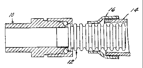
Figure 1 is a partial cross-sectional view of an underground piping system and
fitting
in an exemplary embodiment of the invention;
Figures 2-4 illustrate steps in installing the underground piping system;
Figure 5 is a side view of an alternate embodiment of the invention; and,
Figure 6 is a cross sectional view of an alternate embodiment of the
invention.
DETAILED DESCRIPTION OF THE PREFERRED EMBODIMENTS
Figure 1 is a side view, in partial cross-section, of an underground piping
system and
fitting in an exemplary embodiment of the invention. The underground piping
system
includes flexible piping 12 (such as CSST), a protective conduit 14 and a
sealing member 16.
Flexible piping 12 may include a jacket (not shown). A conventional fitting 10
may be
connected to the flexible piping 12. The protective conduit 14 is a made from
a semi-rigid
material in order to protect the flexible piping 12 while still allowing the
protective conduit

CA 02359047 2007-08-09
-2a-
14 to be coiled for easy handling and transportation. In an exemplary
embodiment, protective
conduit 14 is made from polyethylene. Sealing member 16 seals the gap between
the inner
diameter of the protective conduit 14 and the outside surface of the flexible
piping 12. In an
exemplary embodiment, the sealing member 16 is a heat shrink polyolefin. A
heat source,
such as a heat gun, is used to shrink the sealing member 16 to the protective
conduit 14 and
the flexible piping 12 or the jacket of the flexible piping 12 if so equipped.
Installation of the underground piping system will now be described with
reference to
Figures 2-4. The underground piping system of the invention may be

CA 02359047 2001-07-03
WO 00/43704 PCT/US00/01428
-~-
supplied in a kit containing a predetermined length (e.g. 100 feet or longer)
of flexible
piping 12 positioned within a similar length of protective conduit 14 and two
sealing
members 16. Figure 2 depicts the flexible piping 12 positioned within the
protective
conduit 14. In an exemplary embodiment, the protective conduit has a
cylindrical
cross section. As noted above, the flexible piping 12 is positioned within the
protective conduit 14 to eliminate the need to pull the flexible piping 12
through the
protective conduit 14. The first step of the installation procedure is to
remove a
portion of the protective conduit 14. This is done using a standard tubing
cutter and
results in flexible piping 12 extending beyond the protective conduit 14 as
shown in
Figure 3. At this point, the flexible piping 12 may be cut to a desired
length.
The next step is to place sealing member 16 over the end of the protective
conduit 14 such that the sealing member 16 covers both the protective conduit
14 and
the flexible piping 12 as shown in Figure 4. In an exemplary embodiment,
sealing
member 16 has a cylindrical cross section and has an inner diameter slighter
larger than
the outer diameter of protective conduit 14. In an exemplary embodiment, a
three inch
length of sealing member 16 is used. The sealing member 16 is then heated with
an
appropriate heat source (e.g. heat gun) such that the sealing member contracts
and
seals against both the flexible piping 12 (or piping jacket) and the
protective conduit 14
as shown in Figure 1. The other end of the flexible piping 12 and protective
conduit
14 may be prepared in a similar fashion. A fitting, such as fitting 10 in
Figure 1, may
then be attached to the flexible piping 12 as is known in the art. If
necessary, the
flexible piping 12 can be removed from the protective conduit 14 after
installation by
removing sealing members 16 and pulling the flexible piping 12 from the
protective
conduit 14.
Figure 5 shows an alternate embodiment of the invention which uses a
corrugated protective conduit 15. Also shown in Figure 5 is the jacket 13 of
the
flexible piping 12 described above. The corrugated protective conduit 15 may
be made
from polyethylene. The jacket 13 may also be made from polyethylene. The
corrugated protective conduit 15 provides more flexibility than the
cylindrical
protective conduit 14 described above with reference to Figures 1-4.

CA 02359047 2001-07-03
WO 00/43704 PCT/USOO/01428
-4-
Figure 6 shows another alternative embodiment of the invention. As shown in
Figure 6, the underground piping system includes a vent member shown generally
at
20. Certain regulations may require that the protective conduit 14 be vented.
The
vent member 20 provides for compliance with such regulations. As shown in
Figure 6,
the vent member 20 is implemented, in one embodiment of the invention, using a
tee
joint 22. A first end 24 of the tee joint 22 is connected to the protective
conduit 14
using known techniques such as adhesives. A vent opening 28 in vent tee 22
allows
gas to escape from the protective conduit 14. The second end 26 of the vent
tee 22
may be sealed directly to the flexible tubing 12' using a sealing member 16'
contacting
jacket 13'. Alternatively, the system may include an extension protective
conduit 30
which is connected to the second end 26 of the vent tee 22 using known
techniques.
The extension protective conduit 30 is then sealed to the jacket 13 of
flexible piping 12
by a sealing member 16.
The present invention provides an underground piping system which facilitates
installation. The invention may be embodied in a kit including a protective
conduit
having flexible piping positioned therein, sealing members and vent tees if
necessary.
Although, the invention has been described with respect to underground
installations, it
is understood that it is applicable to installations in concrete slabs and
similar
installations were protection of the flexible piping is needed.
While preferred embodiments have been shown and described, various
modifications and substitutions may be made thereto without departing from the
spirit
and scope of the invention. Accordingly, it is to be understood that the
present
invention has been described by way of illustration and not limitation.

Representative Drawing
A single figure which represents the drawing illustrating the invention.
Administrative Status

2024-08-01:As part of the Next Generation Patents (NGP) transition, the Canadian Patents Database (CPD) now contains a more detailed Event History, which replicates the Event Log of our new back-office solution.

Please note that "Inactive:" events refers to events no longer in use in our new back-office solution.

For a clearer understanding of the status of the application/patent presented on this page, the site Disclaimer , as well as the definitions for Patent , Event History , Maintenance Fee  and Payment History  should be consulted.

Event History

Description Date
Time Limit for Reversal Expired 2016-01-20
Letter Sent 2015-01-20
Grant by Issuance 2008-11-18
Inactive: Cover page published 2008-11-17
Inactive: Final fee received 2008-08-28
Pre-grant 2008-08-28
Letter Sent 2008-03-04
Notice of Allowance is Issued 2008-03-04
Inactive: Approved for allowance (AFA) 2007-11-30
Amendment Received - Voluntary Amendment 2007-08-09
Inactive: S.30(2) Rules - Examiner requisition 2007-06-06
Inactive: IPC assigned 2006-09-07
Inactive: First IPC assigned 2006-09-07
Inactive: IPC removed 2006-09-07
Inactive: IPC from MCD 2006-03-12
Letter Sent 2005-01-14
Request for Examination Requirements Determined Compliant 2005-01-04
All Requirements for Examination Determined Compliant 2005-01-04
Request for Examination Received 2005-01-04
Inactive: Cover page published 2001-11-23
Inactive: Office letter 2001-11-06
Inactive: Notice - National entry - No RFE 2001-11-01
Letter Sent 2001-11-01
Inactive: First IPC assigned 2001-11-01
Application Received - PCT 2001-10-29
Application Published (Open to Public Inspection) 2000-07-27

Abandonment History

There is no abandonment history.

Maintenance Fee

The last payment was received on 2008-01-09

Note : If the full payment has not been received on or before the date indicated, a further fee may be required which may be one of the following

  • the reinstatement fee;
  • the late payment fee; or
  • additional fee to reverse deemed expiry.

Patent fees are adjusted on the 1st of January every year. The amounts above are the current amounts if received by December 31 of the current year.
Please refer to the CIPO Patent Fees web page to see all current fee amounts.

Owners on Record

Note: Records showing the ownership history in alphabetical order.

Current Owners on Record
OMEGA FLEX, INC.
Past Owners on Record
MARK ALBINO
Past Owners that do not appear in the "Owners on Record" listing will appear in other documentation within the application.
Documents

To view selected files, please enter reCAPTCHA code :


To view images, click a link in the Document Description column. To download the documents, select one or more checkboxes in the first column and then click the "Download Selected in PDF format (Zip Archive)" or the "Download Selected as Single PDF" button.

List of published and non-published patent-specific documents on the CPD .

If you have any difficulty accessing content, you can call the Client Service Centre at 1-866-997-1936 or send them an e-mail at CIPO Client Service Centre.


Document
Description 
Date
(yyyy-mm-dd) 
Number of pages   Size of Image (KB) 
Representative drawing 2001-11-14 1 11
Claims 2001-07-02 2 42
Drawings 2001-07-02 2 41
Abstract 2001-07-02 1 41
Description 2001-07-02 4 171
Claims 2007-08-08 2 39
Description 2007-08-08 5 184
Representative drawing 2008-10-27 1 11
Reminder of maintenance fee due 2001-10-31 1 112
Notice of National Entry 2001-10-31 1 195
Courtesy - Certificate of registration (related document(s)) 2001-10-31 1 113
Reminder - Request for Examination 2004-09-20 1 121
Acknowledgement of Request for Examination 2005-01-13 1 176
Commissioner's Notice - Application Found Allowable 2008-03-03 1 164
Maintenance Fee Notice 2015-03-02 1 172
PCT 2001-07-02 5 265
Correspondence 2001-10-31 1 13
Correspondence 2008-08-27 2 58