Note: Descriptions are shown in the official language in which they were submitted.
CA 02359081 2001-07-13
WO 00/43206 PCT/IL99/00668
AUTOMATIC REGISTRATION AND LENGTH ADJUSTMENT
FIELD OF THE INVENTION
The present invention relates in general to optical imaging on a moving
surface and in
particular to automatic registration adjustments of optical images on the
moving surface.
BACKGROUND OF THE INVENTION
Optical imaging on a moving surface is well known, for example in laser
printers and
photocopiers, wherein optical information is imaged or written on the surface
of a
photoconductive drum. Normally, optical information is written onto the
surface of a drum
using stationary optics together with moving optics such as a polygon, a
hologon or a galvano-
mirror to axially scan the drum. US patents 4,796,961; 4,547,038; 4,445,125
and 4,474,422,
5,315,321, which are incorporated herein by reference, describe such optical
imaging systems.
When multicolor optical information is to be imaged or written, a final
compound color
is obtained, in general, by superimposing print separations. Each print
separation has a different
basic color, and the color separation prints are coordinated with and aligned
relative to each
other. In general a plurality of dots or patches, each of different basic
colors, are printed in a
same locality so as to be aligned with or superimposed on each other. Such
superposition of
print separations gives the impression of a full color image having colors
that may be different
from the basic colors.
Normally three or four separations are used, each with a basic color, (or
optionally,
black) in order to obtain a final compound color. In some cases additional
color separations are
also used. The final compound image is obtained by finely adjusting, through
alignment of the
system, the position of each separation, to accurately overlay the separation
prints. The
alignment process and the alignment itself are called registration.
When the separations are printed slightly out of registration, the appearance
of an image
is slightly impaired. However, if the separations are more than slightly out
of registration, the
effect will be disturbing to an observer. In particular, the individual edges
of objects formed by
each one of the separations will separate and the quality of the final
multicolor image will be
greatly impaired.
In order to have substantially perfect registration, the imaging system is
finely tuned
and adjusted prior to a printing task by performing several registration
iterations until the result
is judged acceptable. In practical systems, registration is usually performed
by superimposing a
plurality of separations of predetermined patterns) and visually checking the
patterns for
alignment. The results of the registration are only qualitative and depend on
the skill of the
person who visually checks the degree of coincidence of the separations and
adjusts the printer.
CA 02359081 2001-07-13
WO 00/43206 PCT/IL99/00668
In addition, applicants have found that for some methods of printing digital
images, the
apparent scale of the different color images on the final substrate may vary
from separation to
separation, even if they are all the same size on an image forming surface on
which they are
formed. This results, at best in a composite image in which at least some of
the separations are
S misregistered over at least a portion of the image.
SUMMARY OF THE INVENTION
An object of some preferred embodiments the present invention is to provide a
method
and apparatus for performing image registration, preferably automatically, in
an optical
imaging system, for example, in a laser printing or a photocopying system.
An object of some preferred embodiments of the invention is to provide a
method and
apparatus for determining an amount of image scaling between the various
separations,
preferably automatically, for example, in a laser printing or photocopying
system.
In accordance with a preferred embodiment of the present invention, at least
two
separations of a predetermined shape are printed in the same color to form a
first pattern. This
pattern is configured such that misregistration of the separations changes one
or more
measurable characteristics of the pattern. According to preferred embodiments
of the invention,
these characteristics include one or more of a print shape characteristic and
an average color
density of first printed pattern. The resulting print is compared to a second
pattern, preferably
printed together with the first pattern, whose characteristics, (e.g., shape
andlor average color
density) are not dependent on misregistration of the separations. The second
pattern is
preferably printed utilizing both separations although, in some preferred
embodiments of the
invention, a single separation is used to print the second pattern.
Preferably, the first pattern and the second pattern have the same average
color density
when the separations are registered. Preferably the average color density (or
factors derived
from the average color density) of the first and second patterns are compared
to estimate the
extent of the misregistration. In a preferred embodiment of the invention, the
system
registration is corrected by this estimated misregistration.
Alternatively, the first and second patterns have a characteristic distance.
The
characteristic distance for the first separation is not affected by
misregistration of the
separations and the characteristic distance for the second pattern is affected
by misregistration.
In a preferred embodiment of the invention, a second print of the separations
is
performed with the corrected alignment and this print is checked for
misregistration, which is
then corrected. Preferably, additional iterations are performed until the
misregistration is below
a predetermined value.
2
CA 02359081 2001-07-13
WO 00/43206 PCT/IL99/00668
After a first pair of separations is registered, one of the registered
separations is
preferably registered with a third separation, in the same manner as described
above.
Preferably, the third separation is adjusted in the registration process, so
that after the second
registration all three of the separations are mutually registered. This
process is repeated until all
of the separations used for printing are mutually registered.
In preferred embodiments of the invention, the same color is used to print all
the
separations, during registration, even though different colors will be used
when the final image
separations are printed.
A similar system is used to determine and correct for scale variations between
sequential separations. One way in which such variations can occur is when the
dimensions of
the substrate change between sequential transfer of the separations to it. For
example if the
transfer process utilizes heat then the substrate dimensions will vary with
successive transfers,
since the substrate is heated (up to some temperature) by each of the
transfers. In addition, for
systems that use wet toners or inks, the wetting of the substrate may cause a
change in
dimension.
In order to determine scale changes a series of patterns (as described above)
are printed
along the length and/or along the width of the substrate. The offset of the
separations is
determined as a function of the length (or width) and a best fit for the
function is determined.
This best fit will be of the form: 8(z)= a + bz. The coefficient "a" gives the
required offset or
misalignment correction and the factor "b" gives a scale correction which is
applied to the data.
The scale and offset corrections can be applied to digital data, when the
apparatus is a digital
printer or may be applied as a magnification and offset if the data is in
analog for, as in a
copier.
It should be understood that the above process is most easily applied for
certain system
types. In one such system, a single photoreceptor is used to separately form
latent electrostatic
images of the various separations. The individual separations are developed
using different
color toners and the developed separations are transferred to substrate,
either directly or via an
intermediate transfer member. In many cases, the toners may be liquid toners
and/or the
intermediate transfer member may be heated, which may be among the causes of
the
misalignment/scale problem.
In registering such a system, in accordance with preferred embodiments of the
invention, two latent images corresponding to separations as described above
are formed and
developed with the same toner material to form the images described above.
This results in a
3
CA 02359081 2001-07-13
WO 00/43206 PCT/IL99/00668
single color image for both patterns. This color may be any of the available
colors, used in the
print.
In other systems, the various separations can not be formed in the same color.
Such
systems include systems in which separations are printed in tandem with
different print
engines. These may be electrophotographic systems, other electrographic
systems, or even
ordinary plate printing systems. Other such systems include systems for which
separations are
printed on the same print engine by changing printing plates or masters. Such
systems are
generally ordinary printing plate or printing master systems.
For these systems, the at least two separations may be printed with different
colors.
When different colors are used in a registration procedure, preferably, a
spectral region
common to said colors and preferably a spectral region at which the two colors
absorb light
equally, is first identified. Then the registration procedure is performed,
utilizing light in the
identified spectral region. Preferably, the measurements are performed using
an optical filter
that rejects substantially all the wavelengths outside the identified spectral
region. This region
may be within the normal color extent of the colors or may be in the infra-red
or ultra-violet, if
the visible color extents do not overlap. In some preferred embodiments of the
invention an
additive which is transparent in the visible, but absorbing in the UV or infra-
red may be added
to the inks.
One aspect of the method and apparatus provided in accordance with some
preferred
embodiments of the present invention, relates to obtaining quantitative
information responsive
to a degree of a registration (or misregistration) and/or scale differences of
optical imaging
systems such as, for example, printing or photocopying systems.
In some preferred embodiments of the present invention, an average optical
density
(OD), is measured for both the first and second patterns. From the measured OD
values, dot
areas (DA) are preferably computed and then compared. The amplitude of the
computed DA
values indicates the direction and sign of the misregistration and indicates
the direction and
magnitude of the correction required.
In order to determine scale changes a series of patterns (as described above)
are printed
along the length and/or along the width of the substrate. The offset of the
separations is
determined as a function of the length (or width) and a best fit for the
function is determined.
This best fit will be of the form: 8(z)= a + bz. The coefficient "a" gives the
misregistration or
misalignment and the factor "b" gives a scale error.
In a preferred embodiment of the present invention, the optical density is
measured by a
densitometer. More preferably, the densitometer is operated, in line with the
imaging system,
4
CA 02359081 2001-07-13
WO 00/43206 PCT/IL99/00668
during the registration, so as to measure in real time the optical density of
an overlap produced
on the test sheet.
Alternatively, the average optical densities measured over the first and
second patterns
are used for registration purposes without computing a DA. The measured
average OD values
S are then compared and the direction and amount of the misregistration (and
correction) is
estimated.
If the difference between the measured average OD values or DAs for the two
patterns
is within a given range (corresponding to a given misregistration), the
registration of the optical
imaging system is judged acceptable. Similarly, when scale and misregistration
is to be
corrected, all of the patterns should be within the range. Otherwise, the
registration and/or
scaling operation is iteratively performed until the desired registration
and/or scaling accuracy
is achieved (or the registration and/or scaling fails to meet a convergence
criteria).
An aspect of the method and apparatus provided in accordance with some
preferred
embodiments of the present invention, relates to independently determining the
registration and
scale error relative to one separation for each of the other separations.
Preferably, the
registration and/or scale is optimized for each one of the separations in
order for the imaging
system to have an acceptable registration and/or relative scale level.
There is thus provided, in accordance with a preferred embodiment of the
invention, a
method for registration of print separations in a printer comprising:
(a) printing a first pattern, for which at least one image characteristic
varies relatively
weakly with misregistration, using at least one of first and second
separations;
(b) printing a second pattern, for which said image characteristic varies
relatively
strongly with misregistration, using said first and second separations;
(c) determining at least one image characteristic for the first and second
patterns; and
(d) correcting the mutual registration of the first and second separations
responsive to a
difference in the determined at least one characteristic for the first and
second patterns.
Preferably, the method includes repeating at least (b)-(d) for a third
separation in place
of said second separation.
In a preferred embodiment of the invention, the first pattern is printed
utilizing both
said first and second separations.
In a preferred embodiment of the invention the characteristic is a dot area.
In a preferred embodiment of the invention the characteristic is a hue.
In a preferred embodiment of the invention the dot area is determined from a
measurement of optical density.
5
CA 02359081 2001-07-13
WO 00/43206 PCT/IL99/00668
In a preferred embodiment of the invention the characteristic is an average
optical
density of the pattern.
In a preferred embodiment of the invention the first pattern is printed using
only one
separation.
Preferably, the first and second separations are printed in a same color.
Alternatively,
the first and second separations are printed in different colors.
In a preferred embodiment of the invention the characteristic is an extent.
Preferably,
the first pattern comprises a series of lines having a given spacing pattern
printed using said
first separation and wherein said second pattern comprises a series of lines
having said given
spacing pattern and wherein, in the absence of misregistration, some of said
lines being printed
utilizing said first separation and some of said lines being printed utilizing
said second
separation.
In a preferred embodiment of the invention the characteristic of the first
pattern does
not vary with misregistration.
Preferably, the first pattern comprises at least one first rectangle printed
by said first
separation and having a given extent and at least one second rectangle printed
by said second
separation having a smaller extent than said first rectangle in at least one
direction, said second
at least one rectangle being completely within the first rectangle, such that
the characteristic is
not a function of misregistration of the separations; and
the second pattern comprises at least one, third, rectangle printed by said
first separation
and at least one, fourth, rectangle printed by said second separation
partially overlapping said
third rectangle, the extent of said partially overlapping rectangles having
said given extent
when the separations are registered.
In a preferred embodiment of the invention, the first pattern comprises at
least one first
rectangle printed by said first separation having a first given extent and at
least one, second,
rectangle printed by said second separation having said first given extent
partially overlapping
said first rectangle, the extent of said partially overlapping rectangles
providing a pattern for
which said characteristic varies relatively weakly with misregistration of the
separations; and
the second pattern comprises at least one, third, rectangle printed by said
first separation
and at least one, fourth, rectangle printed by said second separation
partially overlapping said
third rectangle, the extent of said partially overlapping rectangles providing
the same value of
the characteristic as for the first pattern when the separations are
registered, wherein the extent
of the third and fourth rectangles is much smaller than first given extent,
such that the
6
CA 02359081 2001-07-13
WO 00/43206 PCT/IL99/00668
characteristic of the second pattern is much more sensitive to misregistration
than is the first
pattern.
In a preferred embodiment of the invention, the method includes:
identifying a spectral region for which said different colors have a
substantially equal
absorption; and
utilizing a characteristic of said patterns in said spectral region in
registering the
separations.
Preferably the method includes printing a plurality of said patterns and
utilizing an
average value of the characteristic in correcting the registration.
Preferably, the method includes
printing a plurality of said patterns;
determining a functional fit to variations in said characteristics; and
utilizing a zeroth order term in said functional fit to correct the
registration
In a preferred embodiment of the invention, correcting said alignment includes
correcting scale differences between the separations, and including utilizing
a variation in said
characteristic in correcting scale differences between the patterns.
In a preferred embodiment of the invention, correcting said alignment includes
correcting scale differences between the separations and including printing a
plurality of said
patterns and utilizing a variation in said characteristic in correcting scale
differences between
the patterns.
Preferably, the variation used to correct scale is a first order variation of
the
characteristic.
Preferably, the first and second patterns comprise a plurality of repeating
sub-patterns
and wherein an average value of said characteristic over the extent of the
pattern is utilized in
correcting the registration.
In a preferred embodiment of the invention the printer prints said separations
without a
change of printing plates.
In a preferred embodiment of the invention the printer is an electrostatic
printer.
Preferably, the electrostatic printer is an electrophotographic printer.
Preferably, the printer utilizes liquid toner to print. Alternatively, the
printer utilizes
powder toner to print.
In a preferred embodiment of the invention, an intermediate transfer member is
utilized
to transfer the separations between an image forming surface on which the
separations are
formed and a substrate. Preferably, the intermediate transfer member is
heated.
7
CA 02359081 2001-07-13
WO 00/43206 PCT/IL99/00668
In a preferred embodiment of the invention, the patterns are used only for
registration
and are not printed together with an image for which registration is desired.
In a preferred embodiment of the invention the registration serves to align
the printer
and wherein subsequent images, different from the patterns, are printed with
the same printer
alignment.
In a preferred embodiment of the invention the printer uses dedicated plates
for each
separation. Preferably, the printer utilizes printing ink to print the
patterns.
In a preferred embodiment of the invention a same printing engine is used to
print the
separations. Alternatively, different printing engines are used to print the
separations.
In a preferred embodiment of the invention the method includes:
repeating at least (a) -(c) after correcting the alignment in accordance with
(d),
preferably, until said difference is below a given value.
BRIEF DESCRIPTION OF FIGURES
The invention will be more clearly understood by reference to the following
description
of preferred embodiments thereof read in conjunction with the accompanying
figures. Identical
structures, elements or parts that appear in more than one of the figures are
labeled with the
same numeral in all the figures in which they appear.
Figs. lA and 1B schematically show two prints having various print regions,
useful for
carrying out a registration method in accordance with a preferred embodiment
of the invention;
Figs. 2A and 2B show schematically the print patterns in two of the regions of
Fig. lA,
printed in accordance with a preferred embodiment of the invention;
Figs. 3A and 3B schematically show two alternative patterns, useful for
carrying out
registration in accordance with a preferred embodiment of the invention;
Fig. 4 schematically shows a portion of an electrographic system suitable for
registration utilizing a registration method of the present invention;
Fig. S schematically shows a further portion of an electrographic system
suitable for
measurement of the misregistration between various separations; and
Fig. 6 schematically shows two alternative patterns, useful for carrying out a
method in
accordance with a preferred embodiment of the invention.
DETAILED DESCRIPTION OF PREFERRED EMBODIMENTS
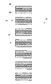
Reference is now made to Fig. lA, which schematically shows a print 30 in
which
various regions are printed in accordance with a preferred embodiment of the
invention.
Print 30 comprises a plurality of regions 32 and 34, which are used to
determine and
correct the registration between a first, reference, separation, and a second
separation. Fig. 1B
8
CA 02359081 2001-07-13
WO 00/43206 PCT/IL99/00668
shows a second print 40 in which regions 36 (together with information from
region 34) are
used to determine and correct the registration between a third separation and
the reference
separation and regions 38 (together with information from region 34) are used
to determine and
correct the registration between a fourth separation and the reference
separation.
Since the alignment of each of the separations with the reference separation
is similar,
only one of the procedures will be described in detail, namely the
registration first pair of
separations, using regions 32 and 34.
Region 32 comprises a series of preferably solidly printed areas 44 as shown
in Fig. 2A.
A portion of the printed area printed with the first separation is marked with
reference numeral
46 and a portion printed with the second separation is marked with reference
numeral 48.
Printed portions 46 and 48 are marked with oppositely oriented diagonal lines,
such that
regions printed with both separations are shown as cross hatched.
Region 34 comprises a series of printed areas 49 as shown in Fig. 2B. The
entire printed
area is printed with the first separation indicated by reference numeral 48'
and marked with the
same diagonal marking as in Fig. 2A. The second separation prints only a small
strip 46' in the
center of the print portion 48'. Strip 46' is marked with the same diagonal
marking as in Fig.
2B. However, since it overlays the print of the first separation, it is shown
as cross-hatched on
Fig. 2B.
In a preferred embodiment of the invention, both separations are printed in
the same
color. A comparison of the prints of Figs. 2A and 2B shows that, when there is
no
misregistration between the separations, they are the same, the only
difference between them
being the way the pattern is formed. Alternatively, the measurement is made in
a spectral
region in which the inks have the same density.
If, however there is misregistration in the print direction (shown as arrow
42), the area
of the prints is different, with the sign of the difference being dependent on
the direction of the
misregistration. This difference is proportional to the amount of the
misregistration. A
computation of dot area based on a measurement of average density will be
roughly
proportional to the actual total printed area and thus to the misregistration.
In general, the dot area (actually percent print) is computed using the
formula:
1-10-(ODs -ODB )
DAs = 1-10-(ODF'-ODB)
where DAs is the effective dot area of a test or reference region 32 or 34 (as
shown in Fig. lA)
and ODs is the average optical density of the region (measured over the
printed and non-
printed areas). ODB is the optical density of the background (i.e., of the
paper on which the
9
CA 02359081 2001-07-13
WO 00/43206 PCT/IL99/00668
image is printed). This may be measured on the areas between the regions. ODF
is the optical
density of a completely printed region, such as a region 45 on Fig. 1. As a
practical matter, the
dot area used for the determination of the misregistration is the average dot
area measured over
all like solidly printed areas and intervening unprinted spaces.
If the system is correctly aligned, the computed DA is the same for regions 32
and 34.
However, if misregistration at the position of 32 and 34 is present, the
computed DA is
different for the two regions, with the sign of the difference being
indicative of the direction of
the misregistration. The amount of the difference is approximately
proportional to amount of
the misregistration, with the proportionality being determined by the geometry
of the printed
areas.
In general, for laser or other systems in which information is written line by
line, the
misregistration to be corrected is system misregistration and not
misregistration in the data
itself. Thus, the present registration system acts to correct for system
misalignments which lead
to misregistration of the separations. In a preferred embodiment of the
invention, the patterns
shown in Figs. 1 and 2 are printed separately from the actual images to be
printed and the
system is aligned. After the system is aligned, any separations which form
actual desired
images will be aligned as well. When the printing system is misaligned, gross
realignment of
the system may be achieved by offsetting the data which is scanned to form the
various
separations by one or more lines. However, for high quality printing the
resulting ~0.5 line
accuracy is not sufficient.
Alternatively to printing the reference pattern with two separations, if a
high density
color (such as black) is utilized, the reference pattern may be printed with
only one separation.
Accuracy of the alignment is believed to be only minimally affected.
If scale differences between the separations are present, it will be
impossible to align the
system over the entire length of the print. In order to effect such alignment,
a scale change of
the data between the separations must be determined. To determine scale errors
the offset of the
separations is determined as a function of the length (or width) and a best
fit for the function is
determined. This best fit will be of the form: 8(z)= a + bz. The coefficient
"a" gives the
required offset or misalignment correction and the factor "b" gives a scale
correction which is
applied to the data. Preferably, the zero of "z" is set at the center of the
page, to minimize
changes in scale an offset to a minimum. The scale and offset corrections can
be applied to
digital data, when the apparatus is a digital printer or may be applied as a
magnification and
offset if the data is in analog for, as in a copier.
CA 02359081 2001-07-13
WO 00/43206 PCT/IL99/00668
Figs. 3A and 3B show reference and misregistration sensitive patterns useful
in a
second preferred embodiment of the registration method of the invention.
The pattern of Fig. 3A comprises thin line pairs 80 that are printed with a
single
separation. The spacing within each line pair is the same and the spacing
between line pairs is
also the same. Preferably, the spacing within a pair is different from the
spacing between pairs.
The pattern of Fig. 3B comprises thin line pairs 82 that appear identical to
those of Fig.
3A. However, alternating lines (84 and 86) are printed utilizing different
separations. Thus the
spacing between lines in a pair and the spacing between pairs will depend on
misregistration
between the separations.
A simple measurement of the distances (for example using the output of an on-
line
detector) allows for the determination of the center to center distance
between the lines.
Differences between the distances measured for the patterns of Figs. 3A and 3B
indicate not
only the amount of the misregistration, but also its direction. Since a number
of line pairs of
each type are present in each pattern and since a number of patterns of each
type are printed,
quite high accuracies can be achieved if the distance measurements are
averaged. In a similar
manner to that described above for Fig. 2, the scale can also be determined.
Fig. 4 shows a printer system, based on that described in U.S. Patent
5,315,321 (which
is incorporated herein by reference), which system makes registration and
scale corrections to
an accuracy better than a scan line. To the extent that elements in Fig. 3 are
not described in the
present application, the reader is referred to that patent for further
details. The system of Fig. 4
as described in this patent corrects for variations in the rotation velocity
of a photoreceptor 8 by
angular adjustment of a galvano-mirror 12. In general, an optical image source
10 sends a
timing signal to control electronics 24 which also receives a signal from an
encoder 9 and an
end-of line sensor 26. Controller 24 controls the position of mirror 12
utilizing a mirror control
20 to adjust the position of the scanning beam on photoreceptor 8 such that
the beam is
correctly positioned on the photoreceptor. Since adjustment of mirror 12 can
be finer than a
single line of the scan, the alignment of the beam can be finer as well. In a
preferred
embodiment of the invention, an additional adjustment of mirror 12 is provided
by controller
24 responsive to an adjustment signal 28, to adjust for the misregistration
measured using the
above described method. Furthermore, control electronics 24 may also control
the scale of the
image being printed either by applying an offset to mirror 12 which is a
function of time (via
control electronics 24) or by changing the scale of a digital image (via
optical image source
10). Scaling algorithms are well known in the art.
11
CA 02359081 2001-07-13
WO 00/43206 PCT/IL99/00668
While the configuration shown in Fig. 4 is preferred, any method useful for
correcting
alignment and/or scale may be used, especially, if it corrects alignment to
better than a single
line.
It should be understood that misregistration of greater than one line may be
first
corrected by shifting data by a whole scan line. Fractional misregistration
may then be
corrected optically or even mechanically.
Fig. 5 shows a portion of an electrographic system suitable for determining
misregistration of separations in accordance with a preferred embodiment of
the invention. Fig.
5 shows a generalized liquid toner electrophotographic printer as is well
known in the art. The
system shown is only exemplary and is used to illustrate the method of
registration and scaling
of the present invention. The methodology of the image formation can be any of
a wide variety
of different available powder or liquid toner systems. In general, the present
invention does not
appear to be tied to any particular system, although the cause and severity of
the problems may
depend on the imaging method and particular imaging system.
In accordance with the normal operation of the system shown in Fig. 5,
photoreceptor 8
is electrified by a corotron , scorotron or other electrifying means S0.
Scanning laser beam or
beams 52 (after reflection from mirror 12) impinge on photoreceptor 8 and form
a latent image
of a particular separation thereon. A dispenser of liquid toner 54, which may
be a spray
dispenser, a series of spray dispensers or a series of slit dispensers, as
known in the art, supply
a liquid toner of a color corresponding to the separation. The latent image is
developed by the
toner to form a visible image on the photoreceptor. A developer roller 56 aids
in the
development and removes both toner that is not used to develop the image and
excess liquid
from photoreceptor 8. A series of scraper blades or other means remove this
material from
developer roller 56 preferably, for reuse. Preferably, a squeegee roller 58
compresses the image
and removes excess liquid therefrom, prior to the transfer of the image to an
intermediate
transfer member 60. The image is then transferred to a sheet 62 held on an
impression roller 64.
After transfer of the image to the intermediate transfer member, residual
toner and
charge on the photoreceptor are preferably removed by discharge and cleaning
apparatus 66
which may be any of the many types that are well known in the art.
The separations are written (by the scanning laser), developed and transferred
to the
sheet, seriatim, in registration. Unfortunately, the registration and/or
scaling may not be
perfect. Thus, in accordance with a preferred embodiment of the invention, the
above described
registration procedure is applied.
12
CA 02359081 2001-07-13
WO 00/43206 PCT/IL99/00668
In a preferred embodiment of the invention, one or more densitometers 68 are
placed
near the surface of sheet 62 to measure the densities of the special prints
used to perform the
alignment in accordance with a preferred embodiment of the invention.
Alternatively, for the
embodiment of Figs. 3A and 3B, simple optical sensors can be used and their
outputs analyzed
to determine the line distances. As indicated above, beams 52 write the
pattern of a first of the
separations shown in Figs. lA, 2A and 2B (or 3A and 3B) to form a latent image
on
photoreceptor 6. This image is developed in one of the colors by elements 54
and 56, as
described above. The developed image is transferred to the sheet. Next a
latent image
corresponding to a second separation is written on the photoreceptor. The
latent image is then
developed, preferably using the same color developer used to develop the first
separation (and
not the color of the second separation). This image is then transferred onto
the image of the
first separation. This results in the printed images shown in Figs. 2A and 2B
(or 3A and 3B). It
should be understood that in some preferred embodiments of the invention, the
images may be
transferred directly to the sheet from the photoreceptor and the intermediate
transfer member
omitted. Alternatively, both images may be transferred to the intermediate
transfer member
before they are transferred together to the sheet.
Densitometer 68 performs the density measurements described above and a
calculator
70 estimates the correction needed to align and/or scale the separations and
sends adjustment
signal 28 to controller 24 as described in connection with Fig. 4.
After the position of mirror 12 is adjusted to apply the desired alignment
correction the
image shown in Figs. lA, 2A and 2B (or 3A and 3B) are preferably printed a
second time with
the corrected alignment. Again the misregistration is measured and the
alignment corrected.
This procedure is repeated until the measured misregistration is below some
predetermined
value such as 5 or 10 micrometers.
After one of the separations is registered with the reference separations a
second image
as shown in Fig. 1B is printed. This image includes patterns 36 and 38,
comprising composite
prints of third and fourth separations respectively with the reference
separation similar to those
shown in Fig. 2B (or 3A). This print does not require patterns of the form of
that shown in Fig.
2B, since the values of OD and DA for this pattern were determined from the
previous print
and may be stored in calculator 70. This second print allows for the
registration and/or scaling
of two more separations with the reference separation, such that all the
separations are mutually
registered. If more than four separations are used, a third print, similar to
that of Fig. lA (or
3A) is printed comprising composite prints of a fifth and sixth separations.
13
CA 02359081 2001-07-13
WO 00/43206 PCT/IL99/00668
In prints printed in accordance with a preferred embodiment of the invention,
regions
46 and 48 (Fig. 2A) are each 14 pixels long in direction 42 with a 7 pixel
overlap and 11 pixel
spacing between printed areas. This results (when alignment is achieved) in a
total printed
length of 21 pixels separated by a 11 pixel spacing. In Fig. 2B, region 46' is
7 pixels long and
region 48' is 21 pixels long. Successive printed regions 48' are separated by
a 11 pixel long
blank areas. It should be noted that if longer printed areas (and unprinted
spaces) are used, the
range of measurable misregistration and scaling is increased. However, this
results in lower
sensitivity and thus, lower accuracy in the alignment measurement. In
preferred embodiments
of the invention, seven repeats of the printed area are provided in each
pattern 32 or 34. Larger
or smaller numbers of repeats may also be provided.
In one preferred embodiment of the invention, two or more densitometers (or
other
optical detectors) 68 are provided and the patterns of Figs. lA and 1B are
printed side by side.
Each of the patterns is scanned by a different densitometer such that the
misregistration of both
may be measured and registered on the same print.
1 S In some preferred embodiments of the present invention, the in-line
densitometer, is for
example, the DTP-24 densitometer of X-Rite.
As shown in Figs. lA and 1B, in addition to the patterns used for the
alignment
measurement, a number of solid bars 47 are preferably printed at the beginning
of the groups of
patterns. These bars comprise a synchronization pattern that provides an
indication to computer
70 that the measurement is about to start. Preferably, these bars are printed
in black to provide
a strong signal, even if the patches themselves are printed in a different
color. Alternatively, the
bars are printed in the same color as the patterns themselves.
In some systems, it is not possible to print a separation in any color other
than the color
it is normally printed. Such systems include other electrographic systems, or
tandem plate
printing presses.
For these systems, the at least two separations may be printed with different
colors.
This produces little problem when utilizing the patterns of Figs. 3A and 3B.
For the patterns of
Figs. 2A and 2B, when different colors are used in a registration procedure,
preferably, a
spectral region common to said colors and preferably a region at which the two
colors absorb
radiation equally, is first identified. Then a set of measurements is
performed, as described
above, limited to identified spectral region. Preferably, the measurements are
performed using
an optical filter that rejects substantially all the wavelengths outside the
identified spectral
region. This region may be within the normal color extent of the colors or may
be in the infra-
red or ultra-violet.
14
CA 02359081 2001-07-13
WO 00/43206 PCT/IL99/00668
Alternatively, when printing for registration and/or scaling correction is
performed in
two colors, a different patterns may be used for the "reference" and for the
other pattern. Fig. 6,
shows a reference pattern 90, side by side with pattern 34', similar to that
of Fig. 2A, that is
more sensitive to misalignment. When the two patterns of the separations are
registered, the
S average density and hue of the two patterns is the same. Both vary with
misalignment but to
different degrees, with the pattern on the left being less sensitive than that
on the right. It
should be noted that when alignment is achieved, both patterns have the same
density and hue,
such that the fact that both vary with misalignment does not deteriorate the
accuracy of the
final alignment. Such systems can also be used to correct scaling errors,
however, more
iterations may be necessary.
Alternatively, the alignment systems of the present invention can be used as
an aid to
alignment of ordinary plate printing presses in which separations are printed
serially on a stack
of pages. In this case, the pattern of the reference separation in Figs. lA,
2A and 2B (or 3A and
3B) is printed along the margin of the image for a first, reference
separation. The entire run of
pages is printed for this separation. The other separations are then printed
serially, as in the
prior art. In a preferred embodiment of the invention, the pattern of the
other (non-reference)
separation of Figs. lA, 2A and 2B (or 3B) are printed along the margin, such
that when any
one separations is aligned with the reference separation, the print of Figs.
lA, 2A and 2B (or
3A and 3B) is printed along the margin.
The second separation is then aligned using the appropriate system described
above.
After such alignment, the entire run of pages (except for some pages to be
used later to register
the other separations) is printed with the second separation. In one preferred
embodiment of the
invention different colors are used for aligning the separations. In another
preferred
embodiment of the invention, the color of the reference separation is used for
registration. The
reference color is then removed and replaced by the desired color for the
second separation.
The third separation is aligned with the reference separation in the same
manner,
utilizing some of the reserved pages printed with the reference separation.
Then, the pages
printed with the first and second separations are printed with the aligned
third separation.
Subsequent separations are preferably aligned and printed in the same manner.
Although, in preferred embodiments of the invention, an in-line densitometer
is used
and an automatic registration adjustment is made, as described above, it is
also possible for the
densities to be measured manually and/or the adjustments to be made manually
in response to
these measurements. This is especially true of plate printing systems in which
the position
adjustments are normally made by turning adjustment knobs and/or for
correction of
CA 02359081 2001-07-13
WO 00/43206 PCT/IL99/00668
misalignment and/or scaling in the direction perpendicular to the process
direction. In a
preferred embodiment of the invention, these adjustments are made
automatically.
During a registration procedure, the registration and/or scale algorithms may
successfully be completed for a given separation while necessitating further
iterations for
another separation. In other words, the registration algorithm may not
converge for all the
separations during the same iteration. For those separations that are
registered earlier than
others, the measurements and adjustments are preferably continued for all the
separations to
improve their registration to the extent possible.
In some preferred embodiments of the present invention, the procedure is
conducted
based only on measured optical densities. The algorithm applied in this case
is much the same
as the algorithm described above except for the fact that the optical density
does not vary
linearly with the imposed offset.
In the description and claims of the present application each of the verbs,
"comprise"
and "include" and conjugates thereof are used to convey that the object or
objects of the verb
are not necessarily a listing of all the components, elements or parts of the
subject or subjects
of the verb.
While the invention has been described with reference to certain preferred
embodiments, various modifications will be readily apparent to and may be
readily
accomplished by persons skilled in the art without departing from the spirit
and the scope of
the above teachings. Various embodiments of the invention have been described
having
specific features. It should be understood that features of the various
embodiments may be
combined, where appropriate and features which are described above may be
omitted, in some
preferred embodiments of the invention. Therefore, it is understood that the
invention may be
practiced other than as specifically described herein without departing from
the scope of the
following claims:
16