Note: Descriptions are shown in the official language in which they were submitted.
CA 02359165 2001-10-17
CONSOLE WITH POSITIONALLY INDEPENDENT
UPPER AND LOWER HALOES
FIELD OF THE INVENTION
The present invention relates to a framework for supporting pieces of work
station equipment, and more particularly to a console structure for supporting
electronic equipment in the nature of computers, video monitors, control
panels and
the like.
BACKGROUND OF THE INVENTION
Control consoles of the type described herein generally include a framework
for receiving and supporting the necessary pieces of electronic and support
equipment including terminals, monitors, keyboards, switch panels, telephone
turrets, lighting and so forth, and a planar work surface extending outwardly
from the
framework at a convenient height. Some of the equipment including video
monitors
and output displays is supported to be visible above the work surface for
convenient
viewing and user access. Attractive finishing panels are also usually
supported by
the basic framework.
To date, many work station consoles have been custom manufactured which
in terms of design and construction is both expensive and time consuming. This
approach has been necessitated by customer requirements that are often unique
in
terms of work station size, equipment placement, human engineering and cost
considerations. In the result, the completed console structures are not only
extremely expensive, but are also difficult if not impossible to subsequently
modify
for the reconfiguration of existing equipment or to retrofit new equipment. An
alternative approach has been to assemble the consoles from fixed size modular
sections. This approach can reduce costs, and although there may be some loss
of flexibility with respect to subsequent modifications and reconfigurations
of
equipment within the console, there are simply many instances in which the
cost
-1-
CA 02359165 2001-10-17
savings outweigh the advantages of a system critically engineered to permit
unlimited post-installation reconfiguration. Some flexibility must however
remain.
A need therefore exists for a console structure which overcomes the problems
inherent in either the custom design and manufacture or completely modular
assembly of console structures. One such approach has been developed by the
Applicant and is described in Canadian Patent 1,291,518 issued October 29,
1991
(equivalent to U.S. Patent 4,836,625).
The backbone of the console structure shown in the aforementioned patents
are the horizontally spaced, vertically upright gable members 1. The gables
are
interconnected by stringers 2 to provide a rigid framework for the console
structure.
The spacing befinreen gables is infinitely variable so that the framework as a
whole
is easily adapted to custom requirements both before and after initial on-site
assembly. Because most of the equipment in the console is supported by or
suspended from the interconnecting stringers, changing the distance between
gables
is not in and of itself all that disruptive of the system as a whole and
particularly the
equipment mounting hardware, and this lends the overall structure enormous
flexibility. This flexibility comes however at a cost. The gables are metal
fabricated
usually from tubular steel and are therefore relatively expensive to
manufacture and
store. The stringers are typically aluminum extrusions and are therefore
relatively
inexpensive linear stock easily stored, but a lot of different stringers of
different
shapes and configurations depending upon function are required and an idea of
the
number and types of stringers needed can be seen from Figures 3 to 9 of the
patent.
This therefore also adds to cost and the need for significant inventory
control. The
need for this number of stringers is made necessary in part because the
gables, as
aforesaid, are almost entirely structural in function and integrate no
channels,
interlocks or other mechanical means that increase their versatility or allow
them to
perform multiple tasks.
The Applicant has found that although there will continue to be a strong
demand for the flexibility and retrofit capabilities of its customized
consoles, and for
modular "discreet logic" systems that cost less, many customers now demand
both
flexability and lower cost. To achieve these objections, it is increasingly
desirable
to further reduce the number of components making up the console framework but
-2-
CA 02359165 2001-10-17
in a way that the remaining components are analogous to toy building blocks
that
can be configured, assembled together and reconfigured for maximum design
flexibility and adaptability. Taking this a step further, one way to reduce
product cost
is to reduce the cost of safes. Particularly in respect of customized product,
an
intense collaboration is normally required between the customer and the
manufacturer, the customer and the sales agent or all three to conceive,
design and
implement the final system. This is an extremely expensive process. However,
by
applying relatively few easily understood and manipulated standard elements,
the
dealer and/or client can achieve near instantaneous design capabilities.
Moreover,
it is contemplated that customers andlor dealers will be given on-line access
to a
computer implemented layout and quoting system that is expected to
significantly
decrease the to configure the consoles to the customer's requirements,
transmit the
order to the factory and deliver the system to the client for assembly.
SUMMARY OF THE INVENTION
The Applicant has therefore developed a console system which is flexible
enough to meet the demands of a custom environment, but wherein the number of
components in the system is significantly reduced for cost savings. Many of
the
remaining components "multi-task", assembly is made easier and less costly,
and
structural integrity is maintained.
The underlying concept of the present console system is that by dividing the
console into positionally independent upper and lower halves, the level of
variability
and flexibility of configuration is substantially increased. This is achieved
through the
application of standard elements.
It is an object of the present invention therefore to provide a console
structure
comprising a relatively few basic components which can be easily assembled
into
a supporting framework for a wide variety of equipment pieces and shapes
without
major modifications to the basic components themselves.
It is a further object of the present invention to provide a console framework
providing as much unimpeded space therein as possible to maximize the
adaptability
of the framework for the mounting of different pieces of equipment at
different
-3-
CA 02359165 2001-10-17
locations, and the ability to meet custom requirements using the same basic
components.
It is a further object of the present invention to provide a console framework
upper turret half of the console that is independently positionable relative
to the lower
base half of the console.
BRIEF DESCRIPTION OF THE DRAWINIsS
Preferred embodiments of the present invention will now be described in
greater detail, and will be better understood when read in conjunction with
the
following drawings in which:
Figure 1 is a front perspective view of the structural framework of a full
depth
console in accordance with the present invention;
Figure 2 is a front perspective view of the console of Figure 1 with finishing
panels applied to the front rear and upper surfaces of the framework;
Figure 3 is a partially exploded perspective view of the console of Figure 2;
Figure 4 is a partially exploded rear perspective view of the console of
Figure
1;
Figure 5 is a front perspective view of the console of Figure 1 including some
internal fitments;
Figure 6 is a side elevational view of the console of Figure 2;
Figure 7 illustrates an individual base frame forming part of the present
console;
Figure 8 is a rear perspective view of the full depth console of Figure 1
including finishing panels thereon;
Figure 9 is a perspective view showing the rear surface of one of the
finishing
panels;
Figure 10 is a front perspective view of a ventilation panel for the full
depth
console of Figure 1;
Figure 11 is a rear perspective view of the panel of Figure 10;
Figure 12 is a top plan view of the panel of Figure 10;
Figure 13 is a rear elevational view of the panel of Figure 10;
Figure 14 is a front elevational view of the panel of Figure 10;
-4-
CA 02359165 2001-10-17
Figure 15 is a right side elevational view of the panel of Figure 10;
Figure 16 is a bottom plan view of the panel of Figure 10;
Figure 17 is a front perspective view of a reduced depth framework for the
present console;
Figure 18 is a side elevational view of the console of Figure 17;
Figure 19 is a partially exploded rear perspective view of the console of
Figure
18;
Figure 20 is a front perspective view of a ventilation panel for the reduced
depth console of Figure 1;
Figure 21 is a rear perspective view of the panel of Figure 10;
Figure 22 is a top plan view of the panel of Figure 10;
Figure 23 is a rear elevational view of the panel of Figure 10;
Figure 24 is a front elevational view of the panel of Figure 10;
Figure 25 is a right side elevational view of the panel of Figure 10; and
Figure 26 is a bottom plan view of the panel of Figure 10.
DETAILED DESCRIPTION
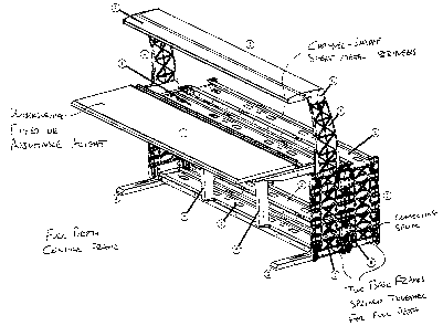
With reference to Figure 1 there is shown a typical console frame in
accordance with the present invention adapted to support various pieces of
computer hardware, lighting fixtures, other pieces of equipment and finishing
panels.
Not all consoles of course are adapted nor required to support computers or
computer controlled equipment but as this is perhaps the most common use for
such
consoles, reference will be made to this application by way of example only.
The types of equipment to be supported by the console will vary
tremendously. The structure must be adapted to support all these different
pieces
of equipment, at locations specified by the customer.
Generally, the present console structure incorporates the following features:
The console is divided into an upper turret half and a lower base half. The
base structure comprises wood, metal or preferably structural foam vertical
frames
and metal horizontal stringers that interconnect the frames into a structural
framework. The base structures are manufactured in modules of preselected
standard lengths such as 24, 48 or 72 inches. The upper turret structure is
-5-
CA 02359165 2001-10-17
constructed of wood, metal or preferably structural foam vertical frames and
metal
(aluminum) horizontal members that interconnect the turret frames and which
can
also function as valances for task lighting and to support equipment front
panels that
fit over monitor screens to trim the space between the screens and the
console. Like
the bases, the turrets are manufactured in standard modular lengths such as,
for
example, 24 inches, 48 inches and 72 inches. The turrets connect to the base
along
the metal stringers, independent of the base frame locations, at discreet
intervals of,
for example, 24 inches. Thus, one turret can span two or more base modules for
example, one 72 inch turret could sit atop three 24 inch base modules.
Conversely,
multiple turrets cari reside on one base, such as one 24 inch turret and one
48 inch
turret, one 72 inch base, or one 48 inch turret straddling one 72 inch base
and one
24 inch base. All of the structural assemblies that make up the turrets, which
can
be single or double high, or can also include desk tops in place of turrets,
behave as
kits that attach to the base stringers in a like manner. The ends of all of
the
modules, including any corners, are consistent, allowing for reconfiguration.
All
internal. fitments, including the likes of monitor shelves, processor shelves,
rack
mounts etc. attach to the base stringers in a like manner, at discreet
intervals.
These internal fitments can span two base modules if required. In a full depth
console, the lower frame system is constructed of two base frames. In a
reduced
depth console, only one base frame assembly is used. This facilitates
migration
from one module type to another through the addition or subtraction of a lower
base
frame. When migrating or reconfiguring from a full to a reduced depth console,
the
omitted frame can be used as the base frame for a second reduced depth base
module.
-6-