Note: Descriptions are shown in the official language in which they were submitted.
CA 02359236 2001-10-16
UP-HOLE OVERSHOT AND SAFETY DRILLING APPARATUS
BACKGROUND OF THE INVENTION
This invention relates to overshot and safety apparatus for retracting a core
barrel inner tube assembly and mechanism to decrease the chances of
unintended movement of the inner tube assembly outwardly of the drill string
which can result in injury to personnel during up-hole drilling (drilling is
at a hole
angle that is above the horizontal).
During up-hole drilling with wire line equipment, the inner tube assembly can
unexpectedly move to and through the outer end of the drill string and injure
someone. For example, if the inner tube assembly is not properly maintained,
it
is possible the inner tube assembly can move to the outer end of the drill
string in
an uncontrolled manner. To stop such outward movement of an inner tube
assembly or the like, it is necessary to consider connecting a device such as
a
"safety sub" at the outer end portion of the drill sting. A sub is usually a
short
coupling having male and female thread connections. Such a sub can have a
closed end or have a minimum inner diameter portion that is of a smaller inner
diameter than the maximum outer diameter of the outer end portion of the
drilling
tool that is used in the drill string, for example, a core barrel inner tube
assembly
or an overshot assembly.
A problem with such a safety sub is that it must be removed from the outer
end of a drill string in order to insert a prior art overshot assembly in the
drill
string preparatory to retrieving a core barrel inner tube assembly when it is
filled
with core. In removing the sub from the drill string, in order to be able to
insert a
wire line overshot assembly, the operator is exposed to the open outer end of
the
drill string through which the drilling tool in the drill string may move
outwardly in
a dangerous manner whereby the operator is exposed to possible injury when
the drilling direction is upwardly. After the overshot assembly is pumped to
the
inner end of the drill string and then attempting to unlatch (uncouple) the
inner
tube assembly from its latched condition in the drill string, it is possible
to have a
mistaken unlatched or a "hung-up" inner tube assembly whereby the overshot
assembly is retracted without the inner tube assembly coupled thereto. Again,
the operator is exposed to possible injury from the drilling tool if and when
it
unexpectedly moves out of the outer end of the drill string.
In U.S. Patent 3,120,283 to Braun there is disclosed an underground
overshot assembly (see Figures 10 and 11) that is fluidly propellable to the
bit
CA 02359236 2009-02-18
2
end of the drill string regardless of the drilling direction. The overshot
assembly
includes a main body pivotally mounting pulling dogs and a valving subassembly
that provides an open fluid bypass channel when being retracted though the
drill
string.
In order to make improvements in overshot and safety apparatus that is
particularly usable in up-hole drilling (a drilling direction above the
horizontal),
this invention has been made.
SUMMARY OF THE INVENTION
The overshot assembly includes a main body mounting pulling dogs for
io movement between an inner tube assembly coupling position and a release
position, an annular seal for forming a fluid seal with the interior of a
drill string,
an elongated overshot tube joined to the main body and valving mechanism
resiliently urged to block axial outward flow through the overshot tube. A
safety
sub is removably mounted to the outer end portion of the drill string while an
overshot adaptor is removably mounted to sub to prevent the overshot assembly
moving inwardly of the sub and to retain overshot valving mechanism in an open
condition. The overshot adaptor includes valving mechanism to permit fluid to
be
pumped inwardly through the overshot adaptor and the overshot tube and block
fluid flow in the opposite direction, the combination of the overshot assembly
and
overshot adaptor being axially slidably movable a limited amount relative to
the
sub. When it is desired to retract an inner tube assembly or other drilling
tool, the
water swivel is removed from the drill string and a disconnect tool is used to
pull
the overshot adaptor to extend outwardly in the sub. Now the overshot adaptor
is
unthreaded from the overshot assembly. Then a wire line adaptor is threaded to
the overshot tube to close the outer end thereof and a loading chamber is
threaded to the sub and fluid under pressure is pumped into the sub for
forcing
the overshot assembly inwardly.
The present invention provides new and novel overshot means for use in
up-hole drilling apparatus that is usable in combination with a safety sub to
minimize danger when a drill tool is in a drill string during up-hole drilling
and the
outer end of the drill string is opened. The present invention also provides
new
and novel overshot and safety apparatus that is retained at the outer end of a
CA 02359236 2009-02-18
3
drill string while a bore hole is being drilled. The present invention further
provides new and novel adaptor means to cooperate with a safety sub and a
new and novel up-hole overshot assembly to retain the overshot assembly
adjacent to the outer end of a drill string while permitting fluid under
pressure
being pumped through the overshot assembly when drilling with a core barrel
inner tube assembly. The present invention also provides new and novel
overshot means that is fluidly propellable in a drill string in an upward
direction
when connected to wire line means and block axial outward fluid flow
therethrough when disconnected from such wire line means and not
io mechanically retained in an unblocked fluid flow position.
According to one aspect of the present invention, there is provided a
drilling apparatus fluidly propellable axially, inwardly in a drill string
from the drill
string outer end to a position to couple to a drilling tool at the drill
string bit end
and retractable axially outwardly by a wire line, comprising an axially
elongated
overshot main body, a pair of pulling dogs having axial outer ends, axial
intermediate portions and axial inner jaws for releasably coupling to the
drilling
tool, pivot means for pivotally mounting the pulling dogs to the main body for
movement between a drill tool coupling position and an overshot release
position, an axially elongated overshot member having an outer end portion, an
2o axial intermediate portion and an inner end portion mounted to the main
body
outer end portion to extend axially outwardly thereof, annular fluid seal
means
mounted to the axial intermediate portion of the overshot member for forming a
fluid seal between a drill string and the overshot member, at least one of the
overshot member and the main body having a fluid bypass channel to bypass
the fluid seal means, at least one of the overshot member and the main body
having a valve seat through which the bypass channel extends, a valve member
mounted to at least one of the main body and the overshot member for limited
movement between a closed position blocking fluid flowing through the valve
seat and axially outwardly through the bypass channel and an open position and
3o resilient means for resiliently urging the valve member to its closed
position while
permitting the valve member moving to its open position when fluid under
pressure is exerted on the valve member in an inward direction.
CA 02359236 2009-02-18
3a
The present invention also provides a drilling apparatus mountable to the
outer end of a drill string that has an axial inner bit end, comprising an
overshot
adaptor and an overshot assembly fluidly propellable axially inwardly in a
drill
string from the drill string outer end to a position to couple to a drilling
tool at the
drill string bit end and retractable axially outwardly by a wire line, the
overshot
assembly including an axially elongated overshot main body having an axial
outer end portion and an axial inner end portion, a pair of pulling dogs
having
axial outer ends, axial intermediate portions and axial inner jaws for
releasably
coupling to the drilling tool, means for mounting the pulling dogs to the main
io body for movement between a drill tool coupling position and an overshot
release position, an axially elongated overshot tube having an outer end
portion,
an axial intermediate portion and an inner end portion mounted to the main
body
outer end portion to extend axially outwardly thereof, annular fluid seal
means
mounted to the axial intermediate portion of the overshot tube for forming a
fluid
seal between the drill string and the overshot tube, a valve seat in one of
the
overshot tube and the main body outer end portion and a port opening to the
overshot tube and radially outwardly axially inwardly of each of the valve
seat
and the fluid seal means, a valve member mounted by at least one of the main
body and the overshot tube, valve member mounting means for mounting the
valve member for movement between a closed position blocking fluid flow
through the valve seat and an open position, means for resiliently retaining
the
valve member in its closed position, and the overshot adaptor being removably
threaded to the overshot tube and having an adaptor tube extending into the
overshot tube when the overshot is threaded thereto for retaining the valve
member in its open position and permitting the valve member moving to its
closed position when the adaptor tube is withdrawn from extending within the
overshot tube.
The present invention also provides a drilling apparatus usable with a
drilling tool and a drill string having an axial outer end and an axial inner
bit end,
comprising an annular safety sub having an axial inner annular end portion
adapted for being threadedly connectable to the drill string outer end, an
annular
outer end portion and an axial intermediate reduced diameter bore portion of a
CA 02359236 2009-02-18
3b
smaller inner diameter than the inner diameter of the inner annular sub end
portion and opening to the inner annular sub end to provide an axially
inwardly
facing shoulder and of a smaller inner diameter than that of the axial outer
sub
end portion and opening thereto to provide an axial outwardly facing second
shoulder, an overshot assembly that includes an axially elongated overshot
tube
having an axial inner end portion and an axial outer end portion of an outer
diameter slidably extendable through the reduced diameter portion, a pair of
axially elongated pulling dogs having axial outer ends, axial intermediate
portion
and axial inner jaws, overshot means mounted to the overshot tube inner end
io portion for mounting the pulling dogs for movement between a drilling tool
coupling position and a drilling tool release position and an overshot adaptor
removably connected to the overshot assembly, the overshot adaptor having an
axial inner adaptor tube extendable into the overshot tube and an axial outer
head portion joined to the adaptor tube and abuttable against the second
is shoulder for limiting the axial inward movement of the overshot assembly
relative
to the sub, the overshot assembly including means abuttable against the first
shoulder for limiting the movement of the overshot assembly and the overshot
adaptor axially outwardly relative to the safety sub.
The present invention also provides a drilling apparatus usable with a
2o drilling tool and a drill string having an axial outer end and an axial
inner bit end,
comprising an annular safety sub having an axial inner annular end portion
adapted for being threadedly connected to the drill string outer end, an
annular
outer end portion and an axial intermediate reduced diameter bore portion of a
smaller inner diameter than the inner diameter of the inner annular sub end
25 portion and opening to the inner annular sub end to provide an axially
inwardly
facing shoulder and of a smaller inner diameter than that of the axial outer
sub
end portion and opening thereto to provide an axial outwardly facing second
shoulder, an overshot assembly that includes a main body, a pair of axially
elongated pulling dogs having axial outer ends, axial intermediate portion and
3o axial inner jaws, means mounted to the main body for mounting the pulling
dogs
for movement between a drilling tool coupling position and a drilling tool
release
position and annular fluid seal means for sealingly engaging the drill string
and
CA 02359236 2009-02-18
3c
an overshot adaptor removably connected to the overshot assembly for limiting
the movement of the overshot assembly inwardly relative to the sub, the
overshot adaptor and overshot assembly having cooperating means extending
axially through the fluid seal means for forming a fluid bypass channel to
permit
axial inwardly flow bypassing the fluid seal means when the overshot adaptor
is
mounted to the overshot assembly while blocking axial outward fluid flow
bypassing the fluid seal means, said cooperating means extending axially
through the fluid seal means, the overshot assembly having means abuttable
against the first shoulder to limit the axial outward movement relative to the
sub.
The present invention also provides in a drilling operation, the steps of
inserting a drilling tool into the outer end of a drill string, then mounting
the
combination of an overshot adaptor, an overshot assembly and a safety sub to
the drill string outer end with the overshot assembly extending in the drill
sting
outer end to prevent the drilling tool moving outwardly of the drill string,
pumping
fluid under pressure axially inwardly through the overshot adaptor and
overshot
assembly while retaining the overshot adaptor and overshot assembly at the
drill
string outer end and preventing axial outward flow through the drill string
when
the pumping in of fluid is discontinued, then after discontinuing the pumping
in
fluid, separating overshot adaptor from the overshot assembly while leaving
the
overshot assembly extending within the drill string outer end, next attaching
a
wire line adaptor to the overshot assembly while the overshot assembly is
still
extending within the drill string, thence pumping fluid under pressure into
the drill
string to fluidly propel the overshot assembly inwardly in the drill string to
couple
to the drilling tool and thereafter retracting overshot assembly.
For purposes of facilitating the description of the invention, the term
"inner" refers to that portion of the drill string, or of the assembly, or an
element
of the assembly being described when, in its position "for use" in, or on, the
drill
string is located closer to the drill bit on the drill string (or bottom of
the hole
being drilled) than any other portion of the apparatus being described, except
where the term clearly refers to a transverse circumferential, direction, or
diameter of the drill string or other apparatus being described. The term
"outer"
refers to that portion of the drill string, or of the assembly, or an element
of the
CA 02359236 2009-02-18
3d
assembly being described when, in its position "for use" in, or on, the drill
string
is located axially more remote from the drill bit on the drill string (or
bottom of the
hole being drilled) than any other portion of the apparatus being described,
except where the term clearly refers to a transverse circumferential,
direction, or
diameter of the drill string or other apparatus being described.
BRIEF DESCRIPTION OF THE DRAWINGS
Figures 1 A and 1 B, when arranged one above the other with their axial
center lines aligned and lines A-A and B-B of Figures 1A and 1 B aligned,
other
than for a part adjacent to the outer end, form a composite longitudinal
section
io through the drilling apparatus of this invention with the safety sub and
overshot
adaptor retaining the overshot assembly at the outer end of the drill string
and an
axial intermediate portion is broken away;
Figure 2 is an enlarged, fragmentary longitudinal sectional view of the
outer end portion of the structure shown in Figure 1A;
Figure 3 is a further enlarged, fragmentary longitudinal sectional view of
an axial intermediate portion of the structure of Figures 1A and 1B;
Figure 4 is an enlarged longitudinal cross sectional view of the outer end
portion of the structure of Figure 1 A together with a disconnect tool shown
in a
CA 02359236 2001-10-16
4
position for being rotated and then pulling the combination of an overshot
adaptor and an overshot assembly to extend outwardly of the safety sub;
Figure 5 is a longitudinal cross sectional view showing the wire line adaptor
threaded to the overshot assembly tube^with the overshot assembly extending
within the safety sub;
Figure 6 is an enlarged longitudinal view of the inner end portion of the
overshot assembly with the overshot adaptor removed therefrom and coupled to
a wire line core barrel inner tube assembly, an axial intermediate part of the
overshot assembly being broken away and only the axial opposite end portions
of the core barrel inner tube assembly being shown;
Figure 7 is a fragmentary transverse cross sectional view of the safety sub,
the overshot adaptor and the overshot assembly, said view being generally
taken
along the line and in the direction of the arrows 7-7 of Figure 2;
Figure 8 is in part a fragmentary view of the safety sub and the outer end
portion of the overshot assembly and overshot adaptor and in part a somewhat
diagrammatic showing of a water swivel and drill rods extending axially
outwardly
of the safety sub, portions being shown in cross section and axial
intermediate
portions being broken away;
Figure 9 is a fragmentary view generally taken along he line and in the
direction of the arrows 9-9 of Figure 4 other than the tool has been rotated
90
degrees; and
Figure 10 is a fragmentary longitudinal view of the tool in the rotated
position
of Figure 9.
DETAILED DESCRIPTION OF THE INVENTION
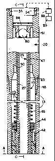
Referring now in particular to Figures IA, IB and 6, there is illustrated an
overshot assembly, generally designated 10, in a hollow drill string 13 which
is
made up of a series of interconnected hollow drill rods (tubes). Even though
the
drilling direction is not shown as being upwardly, the drill string 13 is in
an
upwardly extending bore hole 12 drilled in rock or other types of earth
formations
by means of an annular core bit 11 which is at a higher elevation than the
axial
outer end of the drill string. The pump apparatus located at the drilling
surface
and indicated by block 85 pumps fluid under pressure through a conventional
water swivel 88 and into a safety sub, generally designated 20, which is
removably mounted to the outer end of the drill string 13. The bit in the bore
hole
CA 02359236 2001-10-16
12 may be at a considerable elevation above the drilling surface but at a
considerable depth below the earth surface.
The overshot assembly includes a pair of axially elongated pulling dogs 14
having their intermediate portions pivotally mounted in a slot in the overshot
main
5 body 16 by a pivot pin 15. The outer end portions 14B of the dogs are
resiliently
urged transversely away from one another by a spring 18 mounted on studs 17
that are joined to the dogs (see Figure 6). The movement of the dog jaws 14A
at
the inner end portions of the dogs toward one another is limited by a pin 19
mounted to the main body and extending between the dogs inwardly of the pivot
pin 15.
Referring in particular to Figure 3, the enlarged inner and outer diameter
inner end portion 23A of the axially elongated overshot tube 23 is extended
into
the tubular outer end portion 16B of the main body and secured thereto by a
pin
24. The outer end portion 23B of the overshot tube is internally threaded at
23C
to have the outer end portion of the reduced diameter tubular portion 27A of
adaptor tube 27 of the overshot adaptor, generally designated 25, threaded
thereto (see Figure 2).
The adaptor tubular portion 27A has a plurality of ports 28 closely adjacent
to its inner annular edge 27B which opens to the annular clearance space
radially between the outer peripheral wall of the adaptor tubular portion 27A
and
the inner peripheral wall of the overshot tubular portion 23A. The overshot
tubular portion 23 has ports 29 that open to the above mentioned clearance
space axially outwardly of the main body tubular portion 16B. Mounted in the
overshot tubular portion 23A is a valve member 30 having a head portion 30A
that is resiliently urged by a spring 31 to abut against the inner annular
edge
portion 27B of the adaptor tube 27 when threaded to the overshot tube, the
spring acting between the head portion and the pin 24.
The valve member has a valve stem 30B with an elongated slot 37 through
which pin 24 extends to mount the valve member to the main body for limited
relative axial movement. When the adaptor tube 27 is moved outwardly relative
to the main body 16, the valve member is resiliently moved to have the head
portion 30A abut against the valve seat 32 formed at the juncture of the bore
portions of the enlarged diameter portion 23A and the reduced diameter portion
23B to block fluid flow between ports 29 and the adjacent part of reduced
diameter tubular portion 23B and axially outwardly (see Figure 6). A dog
retainer
CA 02359236 2001-10-16
6
33 is mounted to the inner end portion of the valve stem to move therewith in
the
main body tubular portion 16B between a position extending between the outer
ends of dogs to block the pulling dogs jaws spreading apart to a release
position
to allow the spear point 35A of an overshot coupling member 35 of a drilling
tool,
generally designated 40, move sufficiently axially inwardly between the jaws
for
being coupled to the overshot coupling member when the valve head abuts
against the adaptor tube 27 and a position allowing the jaws spreading to
allow
the overshot assembly be coupled to the overshot coupling member when the
valve member abuts against the valve seat 32 such as shown in Figure 6. The
tool may be any one of, for example, a core barrel inner tube, one having a
plug
bit, an earth sampling tube etc. The tool may be of a type fluidly propellable
to
the bit end of the drill string, for example the core barrel inner tube
assembly of
Figures 3A, 3B, 4A, 4B of U.S. Patent 5,934,393 and Figure 13 of U.S. Patent
5,257,620.
The overshot assembly also includes an annular retainer 41 with the
reduced diameter tubular portion 23B extended therethrough and abutting
against the outwardly facing shoulder formed at the juncture of tubular
portion
23B with the enlarged diametric portion 23A of the overshot tube. The tubular
portion 23B also extends through the annular, resilient fluid seal members 42.
Each seal member has an outer peripheral cylindrical surface portion to at
least
substantially form a fluid sealing fit with the inner peripheral wall of the
drill string
as the overshot assembly moves axially inwardly in the drill string.
Advantageously, each of the fluid seals 42 are of a construction the same as
or
similar to the seal member E of the inner tube assembly of U.S. Patent
5,934,393
that forms a fluid seal with the drill string and thus will not be further
described.
The fluid seal members 42 block fluid flow bypassing the overshot assembly
through the clearance space between the overshot tube 23 and the inner
peripheral wall of the drill string. The seal members are retained between the
annular member 41 and a seal nut 43 that is threaded on the tubular portion
23B
while a retainer nut 44 is also threaded on the tubular portion 23A to abut
against
the annular member 41. The overshot tube 23 has an axiai intermediate portion
extended through a coil spring 45, the inner end of the spring 45 being
mounted
to the retainer nut to extend outwardly thereof.
Referring to Figure 2, the safety sub 20 is tubular and has an axial
intermediate, minimum diameter bore portion 47 of a diameter to have the
_. ,.....~.._.. _ _
CA 02359236 2001-10-16
7
reduced diameter overshot tube portion 23B slidably extended therethrough.
The sub includes an axial inner male pin 48 for being threaded to the outer
end
of the drill string 13 and has an axial bore portion 49 that at its minimum
diameter
part is of a larger diameter than that of bore portion 47 and opens to bore
portion
47 to provide an axial inner facing shoulder 50. The outer end of bore portion
47
opens to a larger diameter bore portion (valve chamber) 51 to provide an
outwardly facing shouider 52 while the opposite end of the bore portion 51
opens
to a larger diameter box portion 54 to provide an outwardly facing shoulder.
The
male pin portion 55 of either a conventional water swivel 88 or the male pin
portion 58 of a loading chamber 57 are threadedly connectable to the box
portion
54.
Referring to Figure 4, a valve body (adaptor head) 73 has an axial inner,
enlarged bore portion 77 opening to the head portion bore 74 of the head
portion
27D of the adaptor tube 27 and an axial outer reduced diameter bore portion 78
opening to bore portion 77 to provide a valve seat 75. One end of a coil
spring
79 is seated against the head portion shoulder 71 and the opposite end abuts
against the valve ball 80 to resiliently retain it against the valve seat to
block axial
outward flow from the adaptor tube 27 to bore portion 78.
The adaptor tube 27 includes an axial outer, annular head portion 27D
having a bore 74 of a larger inner diameter than the inner diameter of the
bore of
tubular portion 27A of adaptor tube 27 and opens thereto to provide an
outwardly
facing shoulder 71 with a plurality of holes 72 opening to the shoulder and
the
bore portion of tubular portion 27A. The head portion has external threads for
being threaded to the internally threaded inner end portion of the valve body
73,
the outer diameter of each of the head portion and the valve body being
greater
than the diameter of sub bore portion 47 whereby the head portion and valve
body are abuttable against shoulder 52 to limit the axial inward movement of
the
overshot adaptor relative to the sub. Further, the valve body is of a lesser
axial
length than the length of the chamber 51. Thus, when the valve body is
abutting
against shoulder 52, the outer transverse surface 73A of the valve body is a
significant distance inwardly of the shoulder 58. Intermediate the valve seat
75
and surface 73A, a pin 84 is mounted to the valve body to extend diametrically
across bore portion 78.
I n order to facilitate moving the overshot adaptor outwardly of the box
portion
54 sufficiently to provide easy access for separating the overshot adaptor
from
CA 02359236 2001-10-16
8
the overshot assembly, there is provided a disconnect tool T that has an axial
outer handle portion 82 and a reduced diameter, axial inner rod portion 79 of
a
diameter to be extendable into the valve body bore portion 78. The axial inner
part of the rod portion has a slot 81 that extends diametrically thereacross
and
opens through its inner transverse surface 79A. Further, the rod portion has
diametrically opposite cutouts 92, 93 axially outward of the transverse
surface
and open to the rod peripheral surface and to the outer end of the slot 81 in
the
same angular direction whereby when the rod portion is moved axially inwardly
to
have the pin 84 abut against the outer end of the slot 81 the rod can be
rotated
about 90 degrees to have the axial inner transverse surfaces 92A, 93A of the
cutouts abuttable against the pin 84. As a result, with the water swivel 85 or
other structure extending outwardly of the box portion 55 separated from the
safety sub, the tool rod portion 79 can be moved into bore portion 78 to have
the
pin 84 extend into the outer end of slot 81 (see Figure 4) and then the tool
rotated to have the pin located in the closed end portions of the cutouts 92,
93
that extend about 90 degrees relative to slot 81 (see Figure 9). Now, upon
moving the tool axially outwardly, the overshot adaptor, together with the
overshot assembly, is moved sufficiently axially outwardly relative to the
safety
sub whereby the overshot adaptor can be separated from the overshot assembly.
In use, with the overshot adaptor separated from the overshot assembly and
the safety sub, the outer end portion of the overshot tube 23 is extended
through
the sub bore portion 49 and into bore portion 47 to extend axially outwardly
of the
sub. The axiai inner end of the adaptor tube is extended into the outer end
portion of the overshot tube 23 and threaded to form a threaded connection at
23C. As the overshot adaptor is extended into and threadedly connected to the
overshot assembly, the adaptor tube 27 forces the valve member 30 inwardly
against the action of spring 31 whereby the dog retainer 33 is moved between
the outer ends of the pulling dogs to prevent the jaws 14A spreading apart
sufficiently to slip over the spear point 35A and couple to the overshot
coupling
member 35. Now, the axial inward movement of the threaded combination of the
overshot adaptor and the overshot assembly relative to the safety sub is
limited
by the valve body abutting against the shoulder 52 while the axial outward
movement is limited by spring 45 abutting against shoulder 50.
After the core barrel inner tube assembly 40 or similar drilling tool is
inserted
into the outer end of the drill string 13, the inner end portion of the
combination of
CA 02359236 2001-10-16
9
the overshot assembly and overshot adaptor is inserted into the drill string,
pushing the drilling tool 40 inwardly and then the safety sub is threaded to
the
outer end of the drill string. Thence, the water swivel 88 is threaded to the
safety
sub to which a supply of fluid under pressure 85 is attached. In the event the
drilling direction is upwardly, the drilling tool is of a conventional type
that can be
fluidly propelled in the drill string adjacent to the bit end 11. If the
drilling tool is
an underground wire line core barrel inner tube assembly, one example being
that of Figures3A and 3B U.S. Patent 5,934,393, fluid under pressure forces
the
valve ball 80 off the valve seat to allow fluid to flow through a bypass
channel, i.e.
through tube 27 and through ports 28, 29 to the annular clearance space
between the overshot main body and the drill string to bypass fluid seals 42
and
force the inner tube assembly inward until its core lifter 34 is located
adjacent to
the bit opening through which the core being drilled extends.
After the inner tube assembly is at the bit end of the drill string, drill
fluid is
pumped into the drill string and the drill string rotated to drill a core. In
the event
the core barrel (not shown) of the inner tube assembly is of an extended type
or
the core barrel is longer than the drill rods being used, during the drilling
operation, pumping of fluid under pressure is discontinued whereby the valve
ball
80 is resiliently moved to prevent axial outward flow in the drill string,
rotation of
the drill string stopped, and then the water swivel removed. Now an additional
drill rod(s) 89 may be threadedly connected to the box portion of the sub and
thence the water swivel 88 threaded to the outer end of said additional drili
rod(s). Thereafter, fluid under pressure is pumped into said additional drill
rod
which forces the valve ball 80 to move inwardly and the drill string rotated
to
continue the core taking operation.
When the core receiving tube (not shown) is filled, rotation of the drill
string
is stopped and the pumping in of fluid is discontinued together with removing
the
water swivel and removing drill rods, if any, extending outwardly of the
safety
sub. Since the valve ball 80 seats on the valve seat, fluid flow axially
outwardly
through the overshot adaptor overshot assembly is blocked. Using the
disconnect tool T, the overshot adaptor overshot assembly combination is
pulled
outwardly in a manner previously indicated to have the outer end portion
thereof
extend outwardly of the sub box portion. Thence the overshot adaptor is
unthreaded from the overshot assembly and withdrawn therefrom. As the
overshot adaptor is unthreaded from the overshot assembly and moves axially
CA 02359236 2001-10-16
outwardly relative thereto, the valve member 30 is resiliently moved outwardly
to
abut against the valve seat 32 to block fluid flow from inwardly of the seals
42
and then through the ports 29 and into tubular portion 23B, the valve member
blocking axial outward flow through the bypass channel provided by the
overshot
5 tube and ports 29. Desirably, the axial length of the threaded the
connection 23C
is sufficiently great that prior to the overshot adaptor being completely
unthreaded from the overshot assembly, the valve member 30 seats against'the
valve seat 32. During the separation of the overshot adaptor from the overshot
assembly, the axial outward movement of the overshot assembly relative to the
10 sub is limited by the spring 45 abutting against shoulder 50. Accordingly,
time is
not lost in having to drain the drill string and insert an overshot assembly
into the
drill string since the overshot assembly is already extending within the drill
string
and water or other drilling fluid in the drill string is not drained from the
drill string.
After the overshot adaptor is removed and while the overshot tube portion is
extending outwardly of the sub box portion, the wire line swivel (wire line
adaptor)
90 with a wire line 91 connected thereto is threadedly connected to the
overshot
tube threaded portion 23C. The male pin 58 of the loading chamber or stuffing
box 57 is threadedly connected to the sub box portion 54 and fluid under
pressure is connected to the loading chamber and pumped into the drill string
to
fluidly propel the overshot assembly to the drilling tool 40 and upon the
pulling
jaws encountering the spear point 35, the jaws are pivoted to their release
position to allow the spear point pass therebetween and then the pulling dogs
are
resiliently urged to their coupling position to couple to the overshot
coupling
member 35. It is noted that during the unthreading of the overshot adaptor
from
the overshot assembly, the dog retainer 33 moves axially outwardly of the
pulling
dogs and as a result the dogs may pivot to move axially inwardly of the spear
point 35A to couple thereto.
After the overshot assembly has coupled to the drilling tool 40 and the
discontinuance of the application of fluid under pressure to the drill string,
the
wire line is retracted whereby the drilling tool 40 is unlatched from the
drill string,
if latched thereto, and the drilling tool and overshot assembly are moved to
have
the coil spring abut against the shoulder 50. If the drilling tool is
retracted with
the overshot assembly, the spring 45 is further compressed and the overshot
assembly extends further outwardly of the sub than the extent of protrusion
after
the overshot adaptor had been disconnected from the overshot assembly and no
CA 02359236 2001-10-16
11
extemal force was applied to the overshot assembly. This can be seen upon
removing the loading chamber from the sub. Only after the operator is certain
that the drilling tool 40 has been retracted with the overshot assembly, the
loading chamber 57 and then the safety sub can be safely removed from the
drill
string and thereafter the overshot assembly and the drilling tool removed from
the drill string. In the event it does not appear that the overshot assembly
has
retracted the drilling tool and more than one attempt is made by pumping the
overshot assembly inwardly in an attempt to retract the drilling tool, greater
precautions have to be taken in removing the sub. The above assumes the
drilling direction is upwardly.