Note: Descriptions are shown in the official language in which they were submitted.
CA 02359694 2001-10-17
RING CONTACT FOR ROTATABLE CONNECThON OF SWITCH ASSEMBLY
FOR USE IN A SURGICAL SYSTEM
BACKGROUND OF THE INVENTION
This invention relates to ultrasonic surgical systems and, more particularly,
to an
improved apparatus for facilitating the performance of surgical procedures
such as
simultaneous soft tissue dissection and cauterization of h~rge and small blood
vessels
through the use of a precisely controlled ultrasonically vibrating instrument,
such as a
1o blade or scalpel.
It is known that electric scalpels and lasers can beg used as surgical
instruments to
perform the dual function of simultaneously effecting the: incision and
hemostatis of soft
tissue by cauterizing tissues and blood vessels. , However, such instruments
employ very
high temperatures to achieve coagulation, causing vaporization and fumes as
well as
15 splattering, which increases the risk of spreading infectious diseases to
operating room
personnel. Additionally, the use of such instruments often results in
relatively wide zones
of thermal tissue damage.
Cutting and cauterizing of tissue by means of sur;~cal blades vibrated at high
speeds by ultrasonic drive mechanisms is also well known. In such systems, an
ultrasonic
2o generator is provided which produces an electrical signal of a particular
voltage, current
and frequency, e.g., 55,500 cycles per second. The generator is connected by a
cable to a
handpiece, which contains piezoceramic elements forming an ultrasonic
transducer. In
response to a switch on the handpiece or a foot switch connected to the
generator by
another cable, the generator signal is applied to the traps<iucer, which
causes a longitudinal
25 vibration of its elements. A structure connects the transdlucer to a
surgical blade, which is
thus vibrated at ultrasonic frequencies when the generator signal is applied
to the
transducer. The structure is designed to resonate at the selected frequency,
thus
amplifying the motion initiated by the transducer. The blade is often non-
symmetrical in
shape and, during the surgical procedure, the physician manipulates the
handpiece to cause
3o the: blade to contact the tissue to be treated. Because the switch which
control operation of
the blade is disposed on the handpiece, the location of the switch may at
times prevent the
physician from contacting tissue with the desired orientation of the blade
because the
relative position between the switch and the blade may prevent or render it
difficult for the
CA 02359694 2001-10-17
2
physician to manipulate the blade to the proper position while still being
able to activate
the switch with his/her fingers.
Thus, there is a need for a handpiece and switch a;~sembly which will permit
the
physician to freely access tissue and operate thereon without having to worry
about the
relative position between the switch and the blade.
SUMMARY OF THE INVENTION
The present invention is directed towards a surgical instrument and, more
particularly, to a surgical handpiece having a switch end cap detachably and
rotatably
1o connected to a handpiece body. Preferably, the surgical instrument
comprises an
ultrasonic surgical instrument which uses ultrasonic vibrations to perform a
surgical
operation. An instrument, such as a blade, e.g., a scalpel blade, is inserted
and secured
within the handpiece body so that a portion of the blade extends beyond the
handpiece
body for contacting tissue and the like. The switch end c.ap includes a switch
mechanism
15 having one or more switch button members for selectively signaling the
level of power
delivered to the handpiece from a power source, e.g., an external ultrasonic
generator.
Preferably, the switch mechanism includes at least two settings, namely a low
power
setting and a high power setting. When the high power setting is selected, the
blade is
ultrasonically vibrated at an elevated level and when the low power setting is
selected, the
2o blade is ultrasonically vibrated at a reduced level. The switch mechanism
is actuated by
pressing a portion of one switch button member depending upon whether high or
low
power is desired for the particular application.
In one exemplary embodiment, the handpiece body is coupled to the power source
by a power cable which extends from one end of the handpiece body. The
components for
25 producing the ultrasonic vibrations include, but are not limited to, a
transducer and a horn
which is connected to the transducer at one end and to the blade at an
opposite end. The
blade preferably is easily attachable/detachable from the horn to permit the
blade to be
easily cleaned, serviced or replaced. The horn extends along a longitudinal
axis of the
handpiece body and at least a portion of the horn extends beyond the end of
the handpiece
3o body where it is coupled to the blade. This end of the h<indpiece body is
configured to
receive one end of the switch end cap in a releasably engaged manner. It will
also be
appreciated that the handpiece body and switch end cap may be semi-permanently
or
permanently connected to one another while still being rotatable ielative to
one another.
CA 02359694 2001-10-17
According to one aspect of the present invention, the handpiece body and the
switch mechanism disposed within the switch end cap are electrically connected
to one
another in such a manner that permits the switch end cap may be freely rotated
about the
handpiece body while the electrical connection is maintained. This permits a
user, e.g. a
surgeon, to rotate the switch end cap during operation of the handpiece in
order to position
the switch end cap in an optimum position relative to the blade. Because the
blade has a
generally non-symmetrical nature, the surgeon may prefer to alter the relative
position of
the switch end cap with respect to the blade in order to conveniently contact
tissue. The
present invention provides such a feature and permits the; surgeon to tailor
the specific
location of the switch end cap for and during a specific surgical operation.
In yet another aspect of the present invention, a seal member is disposed
within the
handpiece body and is preferably formed of an elastic material which
intimately engages a
sheath portion of the blade to form a seal therebetween. The seal member
prevents
unwanted foreign material from entering the inside of the switch end cap and
making
contact with the switch mechanism or other internal components. In a preferred
embodiment, the seal member comprises an annular seaa. member which is
concentrically
disposed relative to the sheath of the blade to form the seal therebetween.
The sheath
member is also preferably formed of an elastic material 'which permits an
effective seal to
be formed.
Other features and advantages of the present invention will be apparent from
the
following detailed description when read in conjunction with the accompanying
drawings.
BRIEF DESCRIPTION OF THE DRAWINGS
The foregoing and other features of the present invention will be more readily
apparent from the following detailed description and drawings of an
illustrative
embodiment of the invention in which:
FIG. I is an illustration of a console for an ultra,.Conic surgical cutting
and
hemostatis system, as well as a handpiece and foot switch in accordance with
an
exemplary embodiment of the present invention;
FIG. 2 is a fragmentary exploded perspective view of one exemplary handpiece
and switch end cap;
FIG. 3 is a longitudinal cross-sectional view of the handpiece;
FIG. 4 is a longitudinal cross-sectional view of the switch end cap;
CA 02359694 2001-10-17
4
FIG. 5 is a cross-sectional view of the handpiece and switch end cap taken
along
the section line 5-5 of FIG. 1;
FIG. 6 is an enlarged cross-sectional view showing the switch end cap with a
portion of the outer surface broken away;
FIG 7 is a fragmentary enlarged cross-sectional view of the electrical
connection
between the switch end cap and the handpiece body and taken along the line 7-7
of FIG. 4;
FIG. 8 is a is a fragmentary exploded perspective view of an exemplary
handpiece
and switch end cap according to a second embodiment;
FIG. 9 is a fragmentary exploded perspective view of an exemplary handpiece
and
1 o switch end cap according to a third embodiment;
FIG. 10 is a longitudinal cross-sectional view of .a rotatable surgical device
according to another embodiment of the present invention; and
FIG. 11 is a side view of a switch end cap according to a fourth embodiment
with
the outer shell being removed therefrom;
15 FIG. I2 is a fragmentary perspective view of an exemplary handpiece
according to
a fourth embodiment; and
FIG. 13 is a fragmentary enlarged cross-sectional view of the electrical
connection
between the switch end cap of the embodiment of FIG. 11 and the handpiece body
of FIG.
I2.
DESCRIPTION OF ILLUSTRATIVE EXEMPLA.R7~ EMBODIMENTS
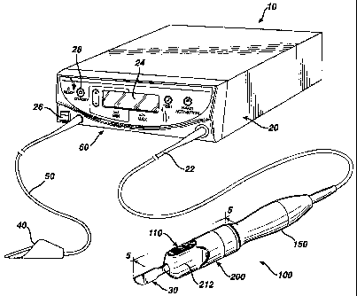
Referring first to FIG. 1 in which an ultrasonic surgical cutting and
hemostatis
system according to the present invention is illustrated acid generally
indicated at 10. The
system 10 includes a console or housing 20 for containing an ultrasonic
generator (not
shown) and a control system located within the console 20 which forms a part
of the
system 10. A first cable 22 connects the.console 20 to a handpiece 100 and
serves to
provide an electrical connection therebetween. The first cable 22 includes a
first set of
wires (not shown) which permit electrical energy, i.e., drive current, to be
sent from the
console 20 to the handpiece 100 where it imparts ultrasonc longitudinal
movement to a
3o surgical instrument 30. According to the present invention, the surgical
instrument 30 is
preferably a sharp scalpel blade or shear. This instrument 30 can be used for
simultaneous
dissection and cauterization of tissue.
CA 02359694 2001-10-17
The supply of ultrasonic current to the handpiece I00 is controlled by a
switch
mechanism 110 disposed within the handpiece 100. As ,will be described in
greater detail
hereinafter, the switch mechanism 110 is connected to tlne console 20, more
specifically
the generator thereof, by one or more wires (not shown) of the first cable 22.
The
generator may also be optionally and further controlled by a foot switch 40
which is
connected to the console 20 by a second cable 50. Thus, in use, a surgeon may
apply an
ultrasonic electrical signal to the handpiece 100, causing the instrument 30
to vibrate
longitudinally at an ultrasonic frequency, by operating the switch mechanism
110 on the
handpiece 100 or the foot switch 40. The switch mecha~usm 110 is activated by
the hand
of the surgeon and the foot switch 40 is activated by the surgeon's foot.
The console 20 also includes a liquid crystal display device 24, which can be
used
for indicating the selected cutting power level in various. means, such as
percentage of
maximum cutting power or numerical power levels associated with the cutting
power. The
liquid crystal display device 20 can also be utilized to display other
parameters of the
system. A power switch 26 and power "on" indicator 2f3 are also provided on
the console
to permit the user to further control the operation of :system I0. Additional
buttons and
control switches, generally indicated at 60, control various other functions
of the system
I O and may be located on the front panel of the console 20.
When the power is applied to the ultrasonic han~tpiece 100 by operation of
either
20 switch mechanism 110 or switch 40, the surgical scalpell or instrument 30
is caused to
vibrate longitudinally at approximately 55.5 KH?, and tlhe amount of
longitudinal
movement will vary proportionately with the amount of driving power (current)
applied, as
adjustably selected by the user. When relatively high cutting power is
applied, the
instrument 30 is designed to move longitudinally in the range of about 40 to
100 microns
at the ultrasonic vibrational rate. Such ultrasonic vibration of the
instrument 30 will
generate heat as the blade contacts tissue. This results because the
acceleration of the
instrument 30 through the tissue converts the mechanics energy of the moving
instrument
to thermal energy in a very narrow and localized area. This localized heat
causes a
narrow zone of coagulation, which will reduce or eliminate bleeding in small
vessels, such
3o as those less than one millimeter in diameter. The cuttvng efficiency of
the instrument 30,
as well as the degree of hemostatis, will vary with the level of driving power
applied, the
cutting rate of the surgeon, the nature of the tissue type and the vascularity
of the tissue.
One exemplary ultrasonic surgical system is disclosed in commonly assigned
U.S. Patent
CA 02359694 2001-10-17
Application No. 09/xxx,xxx, entitled "Ultrasonic Surgical System", filed
October 20,
2000, which is incorporated herein by reference in its entirety.
Referring now to FIGS. 2-7, in which the handpiece 100 is illustrated in
greater
detail, the ultrasonic handpiece 100 houses a piezoelectric: transducer,
generally indicated
at 120, for converting electrical energy to mechanical energy that results in
longitudinal
vibrational motion of the ends of the transducer. The transducer 120 is
preferably in the
form of a stack of ceramic piezoelectric elements with a nnotion null point
between the end
of the stack. A horn 130 is coupled to the transducer 120 on one side.
Instrument 30 is
fixed to a portion of the horn 130. As a result, the instrunnent 30 will
vibrate in the
longitudinal direction at the ultrasonic frequency rate of the transducer 120.
The ends of
the transducer 120 achieve maximum motion when the transducer 120 is driven
with a
current of 380mA RMS at the transducer resonant frequency. This is merely a
general
overview of the operation of the handpiece 100 and one of skill in the art
will appreciate
how the specific components operate to accomplish the ultrasonic surgical
action.
The parts of the handpiece 100 are designed such that the combination will
oscillate at the same resonant frequency. In particular, the elements
contained therein are
tuned such that the resulting length of each element is one-half wavelength.
Longitudinal
back and forth motion is amplified as the diameter closer to the instrument 30
of the
acoustical mounting horn 130 decreases. Thus, the horn 130, as well as the
instrument 30,
are shaped and diminished so as to amplify blade motion. and provide harmonic
vibration
in resonance with the rest of the acoustic system, which produces the maximum
back and
forth motion of the end of the acoustical mounting horn :L 30 close to the
instrument 30.
The handpiece 100 includes a body 150 which ca~ntains internal operating
components, such as but not limited to the transducer I2~0 and the horn 130.
The body 150
is designed to mate with a switch end cap 200 (FIG. 2) which is rotatably
coupled to the
body 150, as will be described in greater detail hereinafter. Preferably, the
switch end cap
200 is detachable connected to the body 150. The body 150 has a distal end 152
and an
opposing proximal end 154 which attaches to one end of~the cable 22. The body
150 may
have any number of shapes and is designed so that a user may easily grip and
comfortably
3o hold the handpiece 100 in one's hand. Preferably, the body 150 is generally
annular in
shape and in the exemplary embodiment, the handpiece 100 has a design with
multiple
tapered sections permitting the user to grasp and rest a thumb and one or more
fingers
around the handpiece I00. In the illustrated embodiment, the body 150 is
formed of a
CA 02359694 2001-10-17
metal material; however, one will appreciate that the body 1 SO may be formed
of a number
of materials, including but not limited to plastic materials.
At the proximal end 154, an electrical adapter 156 is provided and is
electrically
connected to the cable 22 by means of one or more wires (not shown). The
electrical
adapter 156 is also electrically connected to other intern<~.l components of
the handpiece
100 so that power may be selectively provided to the handpiece 100 using the
switch
mechanism 110, as will be described in greater detail hereinafter. The
proximal end 154 is
generally closed ended with the cable 22 being routed th.erethrough, while the
distal end
152 is at least partially open ended. The horn 130 extends in the direction of
the distal end
152 such that a distal tip 132 of the horn 130 extends beyond the distal end
152 of the
handpiece 100. The distal tip 132 has a stud 156 or the like extending
outwardly
therefrom. Preferably, the stud 156 comprises a threaded stud and is designed
to
threadingly mate with the instrument 30 to secure the instrument 30 to the
handpiece 100.
The instrument 30 has a blade portion 32 (FIG. 5) with an insulative sheath 34
disposed
about the blade portion 32. The blade portion 32 also has an exposed blade tip
36 which
extends beyond the insulative sheath 34 so as to be avaullable for contacting
and cutting
tissue and the like. The insulative sheath 34 is formed of any number of
suitable insulative .
materials, and in one exemplary embodiment is formed of a plastics material.
At the distal end 152, the body 150 has a reduced diameter so as to form a
flange
2o member 160 (FIG. 3). The flange member I60 defines a cavity 162 through
which the
horn 130 extends. In the illustrated embodiment, the flau~ge member 160 is
annular in
shape and extends to a location just before the distal tip 132 of the horn 130
so that a
portion of the horn 130, including the distal tip 132, extends beyond the end
of the flange
member 160. A shoulder 164 is formed at the location where the flange member
160
extends from the remaining portion of the body 150. An outer surface 166 of
the flange
member 160 may include one or more ridges, generally indicated at 168, which
extend
annularly around the outer surface 166. In the illustrated embodiment shown in
FIG. 2,
there are two ridges 168 in the form of threads spaced apart from one another
and, because
of the annular shape of the outer surface 166, the ridges 168 comprise annular
threads. It
will be appreciated that the outer surface 166 is constructed so that it
complementarily
mates with the switch end cap 200.
As best shown in FIGS. 2 and 7, the body 150 also includes a first conductive
finger element 170 which is disposed about the horn 130 within cavity 162. In
the
CA 02359694 2001-10-17
exemplary embodiment, the first conductive finger element 170 is an annular
ring-like
member formed of a plurality of fingers 171 radially disposed about the horn
130. Each
finger 171 of the conductive finger element 170 has a serially-connected first
section 172
and a second section 174, which comprises a free end of the finger 171. The
free second
section 174 electrically engages another conductive member when the handpiece
100 is
assembled, as will be described in greater detail hereinafl:er. The second
section 174 is
preferably bent in several locations so that it assumes a generally zig-tag
shape and is
resilient so that the fingers 171 may be bent outwardly under an applied
force. It will be
appreciated that instead of having a plurality of fingers 1'71, only a single
finger 171 may
1o be provided.
At the proximal end of the first section 172, each finger 17I connects to a
first
conductive base ring, generally indicated at 176, which provides a conductive
path
between all of the fingers 171. The first conductive base ring 176 is also
used to properly
locate and position the first conductive finger element 1 TO within the body
150 and more
15 , specifically, within the cavity 162. The first conductive lbase ring 176
is anchored within
the body 150 and is electrically isolated from the conductive body 150 by
using one or
more spacers 178 which are disposed between the body l'.50 within the cavity
162 and the
ring 176. Because of the annular shape of the body 150 ;end the horn 130, the
one or more
spacers 178 are generally in the form of insulative ring structures disposed
between the
2o fingers 171 and the conductive body 150. Typically, the one or more spacers
178 are
formed of any number of suitable plastic materials or elastomeric materials.
The first
conductive finger element 170 is also spaced a sufficient distance from the
horn 130,
which is also formed bf a conductive material, e.g., metal, so that the
fingers 171 or other
part of the element 170 do not make contact with the horn 130 during assembly
of the
25 handpiece I00. By disposing the one or more spacers 178 between the fingers
171 and the
body 150, the spacer 178 serves to slightly urge the fingers 171 inwardly away
from a
conductive inner surface 151 of the body 150.
As previously mentioned with respect to FIG. 3, the cable 22 serves to provide
power to the handpiece and accordingly, the first conductive finger element
170 is
3o electrically connected to the electrical adapter 156 by means of one or
more electrical
wires (not shown) which extend along a length of the body 150 from the
electrical adapter
156 to the first conductive finger element 170. It will also be appreciated
and will be
CA 02359694 2001-10-17
9
described in greater detail hereinafter, that the body 1 SO itself serves as
an electrical
pathway or wire because the body 150 is electrically connected to the cable
22.
As best shown in FIGS. 4-7, the switch end cap 200 which mates with the body
150 so that the switch end cap 200 may freely rotate about the handpiece body
150 during
operation of the handpiece 100. The switch end cap 200 is formed of an outer
shell 201
having a distal end 202 and an opposing proximal end 204 with the proximal end
204 of
the switch end cap 200 receiving and mating with the distal end 152 of the
body 150 (FIG.
4). The shell 20I has an outer surface 206 (FIG. 7) whiclh is contoured to be
gripped and
held by a user during operation of the handpiece 100. The proximal end 204 of
the shell
l0 201 is generally annular in nature and the exemplary shelLl 201 slightly
tapers inwardly to
form a switch section 210 close to the distal end 202. Tl7ds slight taper
forms finger
shaped recessed portions which permit the fingers of a user to easily grip and
hold the
shell 201 as during coupling of the switch end cap 200 to the body 1 SO or
during rotational
movement of the switch end cap 200 relative to the body 150.
The switch section 210 is actually formed of a pair of opposing contoured
finger
sections, generally indicated at 212 (FIG. 1), and a pair of opposing recessed
button
sections, generally indicated at 214 (FIG. 6). Preferably each finger section
212 is formed
about 180° apart from the other finger section 212 and one recessed
button section 214 is
formed about 180° apart from the other button section 214. The holding
and rotational
manipulation of the shell 201 is done by placing a thumb on one finger section
212 and a
finger, i.e., the middle finger, in the other of the finger s<~ctions 212.
This permits the
index finger to rest upon one of the button sections 214. Each button section
214 is
slightly tapered relative to the proximal end 204, while the taper to form the
finger
sections 212 is more pronounced to accommodate resting locations for the thumb
and one
or more fingers.
The outer shell 201 is at least partially open at both the distal end 202 and
the
proximal end 204 with a bore 220 extending therethrough (FIG. 4). The bore 220
is sized
to receive a first conductive member 230 which is securely located within the
switch end
cap 200 by disposing the first conductive member 230 v~rithin the bore 220. In
the
exemplary embodiment, the first conductive member 230 comprises a cylindrical
member
formed of a suitable conductive material, such as a metal. The first
conductive member
230 extends along a length of the outer shell 201 from a point near the distal
end 202 to a
point near the proximal end 204. Preferably, the diameter of the opening at
the distal end
CA 02359694 2001-10-17
1
202 is about the same size as the diameter of the conductive member 230 and is
axially
aligned therewith so as to permit access to the inside of tile conductive
member 230 so that
the instrument 30 may inserted therein and the inside of the conductive member
230 may
be cleaned, etc.
As best shown in FIGS. 5 and 6, at the distal end 202, a seal member 240 is
disposed at the end of the conductive member 230. MorE; specifically, the seal
member
240 is retained in a groove formed in the shell 201 adjacent to the conductive
member 230.
The seal member 240 is preferably formed of an elastic nnaterial, preferably a
plastics
material, and more preferably is formed of silicon. As will be described in
greater detail
to hereinafter, the seal member 240 is designed to prevent umwanted foreign
matter from
entering the inside of the conductive member 230. When the switch end cap 200
mates
with the handpiece body 150, the instrument 30 extends tthrough the conductive
member
230 and exits through the opening formed at the distal end 202 of the switch
end cap 200.
Accordingly, the instnunent 30 extends through the seal :member 240. Due to
the elastic
15 nature of the seal member 240, the seal member 240 engages the sheath 34 of
the
instrument 30 to produce a seal therebetween. This seal prevents the unwanted
foreign
matter from entering through the opening formed at the distal end 202 of the
shell 201
because any matter that might enter, during a surgical operation, is
restricted by the seal
member 240.
2o As best shown in FIG. 6, near the proximal end 204, the switch end cap 200
has an
annular platform 250 formed thereat which is preferably concentric to the
conductive
member 230. The annular platform 250 has an opening i:ormed at the center
thereof
because the bore 220 is formed through the annular platfi~rm 250 and more
specifically,
one end of the bore 220 begins at the annular platform 2'i0. The annular
platform 250
25 extends radially inwardly toward the proximal end 204 and away from another
annular
surface 252 which extends between the inner surface 203 of the shell 201.
Because the
annular platform 250 preferably has a diameter less than the diameter defined
by the inner
surface 203 of the outer shell 201, a gap 254 is formed bE;tween the annular
platform 250
and an inner surface 203 of the shell 201. The annular platform 250 may thus
be thought
3o of as a spacer member. The conductive member 230 has a length such that a
section of the
conductive member 230 extends beyond the annular platform 250 into a cavity
formed
between the inner surface 203 of the shell 201 at the prop;irnal end 204. The
inner
diameter of the shell 201 near the proximal end 204 may vary slightly due to
one or more
CA 02359694 2001-10-17
Ii
lip portions 258 being formed on the inner surface 203 of the shell 201. These
one or
more lip portions 258 serve to provide engaging surfaces for the handpiece 100
when the
handpiece body 150 is coupled to the switch end cap 200.
As best shown in FIGS. 5 and 6, the switch end cap 200 also includes a pair of
switch button members 270 which are detachably secured within the button
sections 2I4
formed in the outer shell 201. Each switch button member 270 has an upper
surface 272
and includes a flange 274 'seating against a retainer 275 firmed as part of
the outer shell
201. The flange 274 seals with the retainer 275 so to prevent any foreign
material and the
like from entering the electronic switch components of the switch mechanism 1
Z 0. The
Io retainer 275 is preferably attached to the outer shell 201 by conventional
techniques,
including a snap-fit arrangement. First and second posts. 276, 278,
respectively, extend
outwardly from the switch button member 270. The first and second posts 276,
278 are
spaced apart from one another with a center traverse wall 280 being formed
therebetween.
The upper surface 272 includes a first raised section 282 and a second raised
section 284
15 I spaced therefrom with a center recessed section 286 being formed
therebetween. The
upper surface 272 is thus slightly beveled as the switch button member 270
transitions
firom the center recessed section 286 to the first and second raised sections
282, 284. In
the illustrated embodiment, the first post 276 is disposed generally below the
first raised
section 282 and the second post 278 is disposed generally below the second
raised section
20 284 so that when a user presses downwardly upon the first raised section
282, the first post
276 is also directed downward. Similarly, when the user presses downwardly
upon the
second raised section 284, the second post 278 is directed downward.
The switch button members 270 are designed to acct as a depressable switch
button
for selectively causing activation of the handpiece 100 as, will be described
in greater detail
25 hereinafter. The switch button members 270 are formed of suitable
materials, such as
plastic materials, and preferably the switch button members 270 are formed of
a resilient
plastic material. In one exemplary embodiment, the switch button members 270
are
formed of silicon which permits the members to be sufficiently resilient
enough so that
they may be fitted and secured within the button sections 214 and also provide
an
3o engagement surface for a finger or thumb during operation of the handpiece
100. In one
aspect of the present invention, the contour of the switch button member 270
permits a
fingertip to easily rest between the first and second raised sections 282,
284. In other
words, the finger tip seats and rests within the center recessed section 286
without
CA 02359694 2001-10-17
12
actuating the switch mechanism 110. Because the switch button members 270 are
disposed within the button sections 214, the switch button members 270 are
spaced about
180° from one another. The recessed section 286 advantageously provides
a location far
the user to rest a finger during operation of the switch button member 270
without
inadvertently activating the switch button member 270. 'This results because
the recessed
section 286 is above the pivot point of the switch button member 270.
The switch end cap 200 also includes a pair of printed circuit boards (PCBs)
290
which form a part of the electronic switch mechanism 110. The PCBs 290 are
disposed
within the outer shell 201 such that the PCBs 290 are disposed between the
conductive
to member 230 and the switch button members 270. The PCBs 290 extend
longitudinally
relative to an axis extending through the bore 220 formed in the switch end
cap 200. A
distal end 292 of each PCB 290 is located near the distal end 202 of the
switch end cap
200 and proximate to the seal member 240. The PCB 290 has a proximal end 294
opposite the distal end 292. It will be understood that instead of using PCBs
290, other
15 suitable electronic components may be used, such as a flexible circuit
component lmown
as a "flexprint".
A pair of fasteners 300 serve to electrically connect the PCBs 290 to the
conductive member 230. More specifically, one side of a switch circuit
according to the
present invention is defined by the conductive member ~',30 since the PCB 290
is
20 electrically connected thereto. The pair of fasteners 300 extend through
openings (not
shown) formed in the PCBs 290 to provide the desired electrical connection
between the
PCBs 290 and the conductive member 230.
As shown in FIG. S, the pair of fasteners 300 are positioned beneath the
center
traverse wall 280. Each button section 214 formed in the outer shell 201
contains
25 openings formed therein and spaced apart from one another for receiving the
first and
second posts 276, 278 of the switch button member 270. The exemplary switch
mechanism 110 is known as a rocker type switch mechanism and, according to the
present
invention, two switch button members 270 form, in part; the switch mechanism
110. Each
switch button member 270 has two switch settings. For example, the first
raised section
30 282 and the first post 276 are associated with a first switch setting and
the second raised
section 284 and the second post 278 are associated with a second switch
setting.
Preferably, the first switch setting of one switch button member 270 is the
same as the first
switch setting of the other switch button member 270 disposed about
180° therefrom. In
CA 02359694 2001-10-17
13
one exemplary embodiment, the first switch setting is a maximum power setting
and the
second switch setting is a minimum power setting. It will be understood that
the opposite
may equally be true, in that the first switch setting may be designed for
causing the
transmission of minimum power to the handpiece 100 and the second switch
setting will
then cause the transmission of maximum power to the handpiece 100.
The PCBs 290 are thus also designed to provide a circuit having two different
switch settings. It will also be appreciated that any number of PCBs 290 may
be used in
the practice of the present invention so long as the PCBs 290 contain circuits
which
provide signals to the generator or the like causing the delivery of at least
two different
levels of power to the handpiece 100 depending upon wYuch portion of the
switch button
member 270 is contacted by the user. One preferred type of PCB 290 is a dome
switch
type PCB 290 in which a first dome (not shown) is formed as part of the PCB
290 for
generating a first signal (e.g., a maximum power signal) when the first dome
is collapsed
under an applied force. The dome switch type PCB 290 also includes a second
dome (not
i5 shown) formed as part of the PCB 290 for generating a second signal (e.g.,
a minimum
power signal) when the second dome is collapsed under an applied force. It
will be
understood that the switch mechanism 110 of the present invention is not
limited to
generating signals for controlling the delivery of power i:o the handpiece 10.
The switch
mechanism 110 may also be used to generate signals which control other
functions of the
2o handpiece 10. For example, the control signals may be used to selectively
control console
functions, including but not limited to, a stand-by function, a diagnostic
function, and
turning the console 20 on and off.
The first dome is disposed underneath the first post 276 so that when the user
depresses the first raised section 282, the switch button member 270 pivots
about the
25 fastener 300 and the first post 276 is directed downwardly through the
respective opening
formed in the button section 214 until contact is made between the first post
276 and the
PCB 290. More specifically, the first post 276 contacts the first dome of the
PCB 290 and
causes the first dome to collapse. When the first dome collapses, electrical
current flows
in a first direction through the PCB 290 and generally tr~rough the switch
mechanism 110.
30 When the user depresses the second raised section 284, the second post 278
contacts and
collapses the second dome and causes electrical current to flow in an opposite
second
direction through the PCB 290 and generally through the switch mechanism 110.
It will
also be understood that the present invention is not lirnii:ed to the use of
domes but rather
CA 02359694 2001-10-17
14
any mechanism which serves to close a normally open switch may be used in the
practice
of the present invention. The collapsing motion of a dome is merely one
exemplary way
of closing a normally open switch.
As best shown in FIGS. 6 and 7, the switch end <;ap 200 also includes a second
conductive finger element 310 which is disposed about the proximal end of the
conductive
member 230. In the exemplary embodiment; the second conductive finger element
310 is
an annular ring-like member formed of a plurality of fin;;ers 3I 1 radially
disposed about
the conductive member 230. Each finger 311 of the conductive finger element
310 has a
first section 312 which is electrically connected to one of the PCBs 290 and a
serially-
connected second section 314 which comprises a free end of the finger 311. The
free
second section 314 makes electrical contact to another conductive member when
the
handpiece 100 is assembled as will be described in greater detail hereinafter.
The second
section 314 is preferably bent in several locations so that: it assumes a
generally zig-zag
shape. The first and second conductive finger elements :170, 310 may be formed
of any
number of suitable conductive materials.
Between the first and second sections 3I2, 314, each finger 3I 1 connects to a
conductive base ring, generally indicated at 316, which provides a conductive
path
between alI of the fingers 311 (FIG. 7). The conductive 'base ring 316 also is
used to
properly locate and position the conductive finger element 310 within the
switch end cap
200. The annular platform 2S0 preferably includes a plurality of radially
spaced tabs (not
shown) which serve to retain the conductive finger element 310 by inserting
the
conductive base ring 316 underneath the tabs such that W a second section 314
of the finger
311 is located between and extends outwardly from adjacent tabs. By anchoring
the
conductive finger element 310 within the annular platform 250, the second
sections 314 of
the plurality of fingers 311 may be manipulated and moved in directions
generally towards
or away from the conductive member 230. The number of fingers 311 may vary
depending upon the precise application and in one exemplary embodiment, the
conductive
finger element 310 includes six (6) fingers 311. The fingers 311 also provide
a
mechanism for releasably retaining the switch end cap 200 to the flange 160.
When the
switch end cap 200 is mated with the handpiece body 150, the fingers 31 I are
flexed
inward by engagement with the inner surface of the body 150. This inward
flexing of the
forgers 311 causes the fingers 311 to apply an outwardly directed biasing
force against the
flange 160 causing retention between the switch end cap :200 and the body 150.
Because
CA 02359694 2001-10-17
the conductive finger element 310 provides, in part, an electrical path for
the handpiece
100, it is important that the conductive finger element 310 not touch the
conductive
member 230. It will be appreciated that the switch end cap 200 preferably
includes a
number of other spacer members which serve to further isolate the conductive
members of
5 the switch end cap 200, namely the element 310 and member 230.
All of the conductor members used in the surgic~~l device 10 (FIG. 1) of the
present
invention are formed of any number of suitable conductiive materials. In one
exemplary
embodiment, the conductive members are formed of staiinless steel, gold plated
copper,
beryllium copper, titanium nitride, or conductive plastics which serve to
reduce the
10 tendency of the members to corrode from harsh cleanin~; solutions or
autoclaving.
The assembly and operation of the handpiece 10~D will now be described with
reference to FIGS. 1-7. The switch end cap 200 is removably attached to the
handpiece
body 150 by aligning the stud 156 and the horn 130 with the inside of the
conductive
member 230. After the stud 156 and the horn 130 are aligned with the bore
formed in the
15 conductive member 230, the switch end cap 200 is brou;;ht into engagement
with flange
member 160 causing the stud 156 and a portion of the horn 130 to be disposed
inside of
the conductive member 230 when the switch end cap 200 is properly fitted about
the body
150. However, the stud 156 and the horn 130 do not make contact with the
conductive
member 230 when switch end cap 200 is attached to the body 150. The proximal
end 204
of the switch end cap 200 seats proximate to or against the shoulder 164. As
stop 391
formed in the switch end cap 200 engages distal end 152 of the body 150,
thereby
providing a stop which restricts further movement of the: switch end cap 200.
Because the stud I56 and a portion of the horn 1:30 are disposed inside of the
conductive member 230 at a proximal end thereof, the ixistrument 30 is secured
within the
switch end cap 200 by securing the instrument 30 to the stud 156. More
specifically, the
instrument 30 preferably has a threaded bore formed therein at an end opposite
the blade
tip 36 (FIG. 3). The instrument 30 preferably attaches to the stud 156 by
threadingly
engaging the threaded bore with the threaded stud 15b rE;sulting in the
instrument 30 being
secured to the stud 156. The instrument 30 is easily removed for cleaning or
replacement
3o thereof by simply twisting the instrument 30 in one direction until the
instrument 30
disengages the stud 156. When the instrument 30 is secured to the stud 156,
the insulative
sheath 34 of the instrument 30 contacts and forms a seal with the seal member
240 so that
unwanted foreign matter is prevented from traveling through the opening formed
in the
CA 02359694 2001-10-17
16
distal end 202. Because of the resilient nature of the seal member 240, the
seal member
240 conforms to the blade shape and the resilient nature of the insulative
sheath 34 further
provides an effective seal.
In accordance with another aspect of the present invention, the first and
second
conductive finger elements 170, 310 provide an electrica pathway between the
switch
mechanism 110 of the switch end cap 200 and the cable 22, which provides the
means for
delivering power to the handpiece 100. As best shown in FIG. 7, when the
switch end cap
200 is attached to the body 150 and the fingers 17I of th.e first conductive
finger element
170 contact and are biased against an outer surface 231 of the first
conductive member 230
l0 of the switch end cap 240. This results because the first conductive member
230 is
disposed between the fingers 171 and the horn 130 as the switch end cap 200 is
attached.
Because of the conductive nature of both the first conductive member 230 and
the fingers
I71, an electrical pathway is formed between the PCBs :?90 and the cable 22.
This
electrical connection also serves to complete one side of the circuit of the
switch
1 s mechanism 110 when one of the switch button members 270 is depressed to
cause one of
the domes to collapse, thereby permitting current to flow through the PCBs
290. Once the
user releases either of the first and second raised section:> 282, 284 (which
the user had
previously depressed), the dome expands and the electrical pathway is
interrupted, thereby
interrupting the flow of current through the switch mechanism 1 I0. This stops
the
2o delivery of power to the handpiece 100. It will also be appreciated that
the switch
mechanism 110 of the present invention may include only a single button member
270.
While, the switch mechanism 110 has been generally discussed as being a
normally
open switch assembly in which a mechanism (such as on.e or more domes) is
activated to
cause the closing of the switch, one of skill in the art will appreciate that
the switch
2s mechanism 110 may be a normally closed switch assembly. In this
embodiments,
depressing one of the sections 282, 284 will cause one of"the switches to open
and not
close as in the other embodiment. Because the dual switch mechanism 110 has
current
flowing in first and second opposing directions, the opening of one switch
will leave
current flowing only in a single direction. In this embodiment, the generator
or the like
30 will have a sensing mechanism, such as sensing circuit, which is designed
to detect the
current flowing in the single direction and equate this to the activation of
one of the
sections 282, 284.
CA 02359694 2001-10-17
17
A first electrical pathway is thus specifically defiined by the PCBs 290, the
fasteners 300, the conductive member 230, the fingers 1'71 and one or more
wires
electrically connecting the fingers 17I to the cable 22. In other words, the
connection
between the fingers 171 and the conductive member 230 serves to electrically
bridge the
body 150 and the switch mechanism 110 together. Electrical current flows
through the
cable 22 and then through the one or more wires to the first finger element
170. The
current then flows into the switch mechanism 110 by mE;ans of the electrical
connection
between the fingers 171 and the conductive member 23CI once the switch
mechanism 110
is actuated by manipulation of one of the switch button members 270.
to ~ In a similar manner, the fingers 311 of the second conductive finger
element 300
contact and are biased against the body 150 of the handpiece 100. Because the
body 150
in this embodiment is formed of a conductive member and is electrically
connected to one
or more wires of the cable 22, the body 150 comprises a conductive member
which can be
used to complete the circuit of the switch mechanism 110. The fingers 311 are
spaced
~5 sufficiently away from the conductive member 230 so that the fingers I71
are actually
disposed between the fingers 311 and the conductive member 230 when the switch
end
cap 200 is attached to the body 150.
The resilient nature of the second sections 314 o:f the fingers 311 permits
the
fingers 311 to contact the body 150 and flex inwardly or outwardly relative
thereto as the
2o switch end cap 200 is attached. Because the first sections 312 of the
fingers 311 are
electrically connected to the PCBs 290, the contact between the second ends
314 and the
body 150 completes the circuit of the switch mechanisms 110 and permits
current to flow
through the body 150 and the second conductive finger element 310 once the
switch
mechanism 110 is actuated. In other words, a second electrical pathway is
formed and is
25 defined by the PCBs 290, the second conductive finger element 310 and the
body 150.
The switch mechanism I I O may be though of as including four (4) switches
with
each having a diode in series. More specifically, first raised section 282 of
one switch
button member 270 corresponds to a first front switch, the second raised
section 284 of the
one switch button member 270 corresponding to a fixst rear switch, the first
raised section
30 282 of the other switch button member 270 corresponding to a second front
switch, and
the second raised section 284 of the other switch button member 270
corresponding to a
second rear switch. It will be understood that each of the aforementioned
front and rear
switches has a diode in series with one another. Preferalbly, the first and
second front
CA 02359694 2001-10-17
18
switches have the same diode orientation and the first arid second rear
switches have the
same opposite diode orientation. The polarity of the diode depends upon
whether the
diode is part of the front or rear switches. When a user <iepresses one of the
first raised
sections 282, the corresponding first or second front switch will be actuated
due to the
associated PCB dome collapsing due to the force applied by one of the first
posts 276.
This causes current to flow in a first direction through the handpiece 100.
When a user
depresses one of the second raised sections 284, the corresponding first or
second rear
switch will be actuated due to the associated PCB dome collapsing due to the
force applied
by one of the second posts 278. This causes current to flow in an opposite
second
1~ direction through the handpiece 100. Thus, in this embodiment, there are
four domes
formed as part of the PCBs 290 with two domes being firmed on each PCB 290.
The handpiece 100 may be designed so that the front switches comprise maximum
power switches with the front diodes thereof serving to :>ignal the delivery
of maximum
power to the handpiece 100 for maximum vibration of the instrument 30. In this
embodiment, the rear switches comprise minimum power switches with the rear
diodes
thereof serving to signal the delivery of the minimum power to the handpiece
100 for
minimum vibration of the instrument 30. The generator is designed so that upon
sensing
current in the first direction from the actuation of one of the front
switches, the generator is
programmed to deliver maximum power to the handpiece 100 and similarly, when
the
generator senses current in the second direction, the generator delivers
minimum power to
the handpiece 100. If one of the front switches and one ~of the rear switches
are accidently
depressed at the same time, the generator will sense current in both the first
and second
directions. Upon sensing the opposing cuirents, the generator is programmed to
stop
delivering power to the handpiece 100 until the condition is rectified.
Preferably, an error
or warning message will also appear on the liquid crystal display device 20.
Importantly, the fingers 171 of the first conductive finger element 170 and
the
fingers 311 of the second conductive finger element 310 do not contact one
another during
operation of the handpiece 100. If one of the fingers 171 were to contact one
of the fingers
311, an electrical short would likely result because the elLectrical pathways
have been
3o crossed. If an electrical short exists in the handpiece l Ot), the
generator will sense current
in both the first and second directions, thereby causing the generator to stop
delivering
power to the handpiece 100 and optionally generate some type of error or
warning
message.
CA 02359694 2001-10-17
19
In another aspect of the present invention, the switch end cap 200 is free to
rotate
about the handpiece body 150 without disrupting the electrical connection
provided
between the cable 22 and the switch mechanism 110 housed in the outer shell
201. The
one or more ridges 168 formed on the flange member 160 provide annular
surfaces for the
inner surface 203 of the switch end cap 200 to ride along; as the switch end
cap 200 is
freely rotated about the distal end 154 of the body 150. l3ecause the switch
end cap 200
and the body I50 advantageously are electrically connected by the rotatable
first and
second conductive fingers elements 170, 310, the switch end cap 200 and the
body 150 are
free to rotate relative to one another without causing an interruption in the
flow of current
within the handpiece 100. The second sections 174, 314 of the forgers 171, 31
l,
respectively, are sufficiently biased against the corresponding complementary
conductive
surfaces so that the second sections 174, 314 rotationally slide along these
conductive
surfaces. Thus, the switch end cap 200 may be rotated about the body 150 to a
desired
position and continues to remain in electrical communication with the body 150
and the
generator regardless of the position of the switch end cap 200. Because most
blades 30 are
non-symmetrical in nature, the surgeon may prefer to alter the relative
position of the
switch button members 270 to the instrument 30 which is held in one position
within the
handpiece 100. The finger elements 170, 310 permit this.
The present invention overcomes the deficiencies. of the conventional surgical
2o devices liy a means for switch electrical communication without the need
for hard wiring. .
This permits the switch end cap 200 to be easily detached from the body 150
for cleaning
and other purposes. For example, the design permits easy inspection of the
members
providing the electrical communication between the switch end cap 200 and the
body 150.
Therefore, the integrity of the first and second conductive finger elements
170, 310 may be
checked at any time to ensure that they remain in working condition. Also, if
the need
arises to replace or service either the switch end cap 200 or the handpiece
body 150, the
two components are quickly and easily separable and replacement or servicing
may be
done. This permits the surgical operations to continue in. an unimpeded
manner.
The switch end cap 200 is also ergonomically designed in that the two switch
3o button members 270 are disposed about 180° apart from one another
because this provides
a preferred orientation where the user (surgeon) may easily contact both
switch button
members 270 as the handpiece 100 is being grasped by the user. By placing the
switch
button members 270 in more than one location, the user may easily and quickly
CA 02359694 2001-10-17
manipulate one switch button member 270 closest to the activating finger(s).
In other
words, it has been found that during a typical manual manipulation of the
switch end cap
200, one thumb and one or more fingers are generally positioned 180°
apart from another
and this complements the positioning of the two switch button members 270. The
180°
5 orientation also has strategic benefits in that if the switch button members
270 were placed
at multiple locations, such as three, it would be difficult for the user to
grasp the surgical
device 10 without possibly contacting and engaging one of the switch button
members
270. In the present design, the 180° orientation provides a grasping
area in which the
user's fingers do not contact the switch button members 270 when the user is
holding the
1o device 10. Other design features, e.g., opposing contoured finger sections
212, are
designed to also provide the switch end cap 200 with a better feel and permit
the user to
easily grasp and rotate the switch end cap 200.
The present invention thus provides a surgical handpiece 100 in which the
switch
mechanism 110 of the switch end cap 200 is electrically connected to the
handpiece body
15 150 in such a manner that permits the switch end cap 20~D to be freely
rotated about the
handpiece body 150 while the electrical connection is maintained.
While the present invention has been described as being a freely rotatable
system,
it also within the scope of the present invention that the laandpiece 100 may
be only
partially rotatable. In this instance, a number of stoppers or detents (not
shown) are
2o incorporated into the structure of the handpiece 100 so that the switch end
cap 200 may
only be partially rotated with respect to the handpiece body 150. The degree
of rotation
may thus be selected by the manufacture and the stoppers or detents positioned
accordingly. In another embodiment, the detents may be; formed so that the
switch end cap
200 is rotated incrementally in a ratchet like manner. Once again, these
detents may be
formed and complementary enageable features are also formed to provide this
ratcheting
effect. Also, the handpiece 100 may be designed to pro~~ide indexable rotation
where the
rotation of the switch end cap 200 is indexed relative to the instrument 30.
For example,
the instrument 30 may be designed so that upon being fastened to the horn 130,
the
instrument 30 always assumes one orientation. For example, the instrument 30
may
3o assume a north-south (vertical) orientation. By using detents and the like,
the rotation of
the switch end cap 200 may be indexed so that the switc',h end cap 200 is
initially in a
predetermined first position and rotation of the switch exid cap 200 causes
the switch end
cap 200 to rotate in predetermined increments, e.g., 90° increments.
This permits the most
CA 02359694 2001-10-17
21
favored positions of the switch end cap 200 to be provided for by the indexed
rotation
system.
It will also be understood that the present invention broadly discloses a
method of
providing rotation between the switch end cap 200 and the handpiece body 150
where a
predetermined number of conductive pathways are formed by mating electrical
conductors. Each pair of mating electrical conductors is designed to convey an
independent electrical signal.
Turning now to FIG. 8 in which another embodiment of the present invention is
illustrated. This embodiment is similar to the first embodiment shown in FIGS.
1-7 in that
1o the handpiece body 150 and the switch mechanism 110 /FIG. 1) disposed
within the
switch end cap 200 are detachable relative to one another and are electrically
connected to
one another in such a manner that permits the switch end cap 200 to be freely
rotated about
the handpiece body 150 while the electrical connection is maintained
therebetween.
However, the mechanism in this embodiment is different with respect to the
second
embodiment of FIG. 8. For purpose of illustration, it will be understood that
the handpiece
body 1 SO and switch end cap 200 of FIG. 8 are essentially identical to those
described in
the first embodiment with the differences being noted herein. More
specifically, the
handpiece body 150 includes a first conductive ring 400 and a second
conductive ring 410
which are securely disposed within the handpiece body 1.50.
2o ~ In one exemplary embodiment, the first conductive ring 400 comprises a
ring
member which is disposed between the handpiece body 150 and the horn 130.
Preferably
the first conductive ring 400 is formed adjacent to the flamge member 160
within the cavity
162 and is electrically isolated from other electrical components. The first
conductive ring
400 is anchored to and extends upwardly from a non-conductive platform or the
like (not
shown) which is formed within the handpiece body 150. The first conductive
ring 400 is
electrically connected to the cable 22 (FIG. 1) by means of one or more
electrical wires
(not shown) which extend along the length of the body 150 from the electrical
adapter 156
(FIG. 3) to the first conductive ring 400.
The second conductive ring 410 of the handpiece body 150 similarly comprises a
3o ring member which is disposed between the handpiece body 150 and the horn
130. The
second conductive ring 410 is disposed between the first conductive ring 400
and the horn
130 and therefore the first and second conductive rings 400, 410 are
concentric members.
The second conductive ring 410 is likewise electrically i:>olated from the
first conductive
CA 02359694 2001-10-17
22
ring 400 and other electrical components contained within the body 150.
Similar to the
first conductive ring 400, the second conductive ring 4117 preferably is
anchored to and
extends upwardly from the non-conductive platform. It will be understood that
the first
and second conductive rings 400, 410 are sufficiently spaced from one another
so that they
are electrically isolated from each other. This may be accomplished by using
one or more
spacers 4I3 disposed between the first and second conductive rings 400, 410 or
between
the rings 400, 410 and other members within the handpic:ce body 150. The
second
conductive ring 410 is also electrically connected to the .cable 22 (FIG. 1)
by means of one
more electrical wires (not shown) which extend along the length of the body
150 from the
electrical adapter 156 (FIG. 3) to the second conductive Bring 410. The second
conductive
ring 410 is thus provided to partially define a second electrical pathway from
the cable 22
to the switch mechanism 110 (FIG. 4).
It will be appreciated that in this embodiment, the handpiece body 150 is
preferably formed of a non-conductive material, such as a plastic material,
because both
is electrical pathways within the handpiece body 150 are defined by the first
and second
conductive rings 400, 410 (with their respective electric wires) and not the
handpiece body
150 itself as in the first embodiment. As will be described in greater detail
hereinafter, a
first planar contact surface 401 of the first conductive ring 400 and a second
planar contact
surface 411 of the second conductive ring 410 provide conductive surfaces
which engage
2o complementary conductive members of the switch end cap 200 to provide the
electrical
connection therebetween.
The switch end cap 200 is modified so that the member 230 (FIG. 7) does not
serve
as a conductive member but rather comprises a member which simply receives the
horn
130 and the instrument 30 (FIG. 1). Accordingly, the member 230 is not
electrically
25 connected to the PCBs 290 (FIG. 4) and may be formed of a non-conductive
material, such
as a plastic. In addition to the second conductive element 310 (FIG. 7), the
switch end cap
200 of FIG. 8 includes a third conductive element 420. In one exemplary
embodiment, the
third conductive element 420 comprises an annular ring-like member formed of a
plurality
of electrical contacts 421 radially disposed about the member 230. The
contacts 42I may
3t) be in the form of fingers, pins, or the like. The third conductive element
420 is disposed
between the second conductive element 310 and the member 230. Similar to the
second
conductive element 310, the third conductive element 42t) is electrically
connected to the
PCBs 290 (FIG. 4) by means of one or more electric wires (not shown). Thus,
the third
CA 02359694 2001-10-17
23
conductive element 420 and not the member 230 is electrically connected to the
PCBs 290
(FIG. 4) to thus complete one side of the circuit of the switch mechanism 110
(FIG. 4)
once one of the switch button members 270 (FIG. 4) is dlepressed to cause one
of the
domes to collapse, thereby permitting current to flow through the PCBs 290
(FIG. 4).
In accordance with this embodiment of the present invention, the second and
third
conductive elements 310, 420 and the first and second conductive rings 400,
410 provide
first and second electrical pathways between the switch mechanism 110 (FIG. 1)
of the
switch end cap 200 and the cable 22 (FIG. 1), which provides the means for
delivering
power to the handpiece 100 (shown entirely in FIG. I). :More specifically,
when the
1o switch end cap 200 mates with the handpiece 100, the second conductive
element 310
engages the first planar contact surface 401 of the first conductive ring 400
to establish the
first electrical pathway. Because the second conductive element 310 comprises
an annular
member having radially spaced contacts 311, the rotation of the switch end cap
200 causes
the contacts 311 to ride along the first planar contact surface 401. Contacts
311 may be in
15 the form of conductive fingers, pins, or the like. As the switch end cap
200 is rotated and
the contacts 311 ride along the surface 401, the first electrical pathway is
maintained.
Similarly, the contacts 421 of the third conductive finger element 420 engage
the
second planar contact surface 411 of the second conductive ring 410 to
establish the
second electrical pathway. Because both the third conductive finger element
420 and the
2o second conductive ring 410 comprise annular members, the switch end cap 200
may be
freely rotated without disruption of the electrical connection between the
switch
mechanism 110 (FIG. 4) and the handpiece 100. In this embodiment, the contacts
311,
421 are generally disposed longitudinal to the first and second conductive
rings 400, 410.
The rotatable connection between the contacts 3'L I, 421 and the first and
second
25 rings 400, 410 serves to electrically bridge the body 150 and the switch
mechanism 1 I O
(FIG. 4) together. Electrical current flows through the cable 22 (FIG. 1) and
then through
the electrical wires to the first and second conductive rings 400, 410. The
current then
flows through the fingers 31 l, 421 to the switch mechanism 110 (FIG. 4) once
the switch
mechanism 100 (FIG. 4) is actuated by manipulation on one of the switch button
members
30 270 (FIG. 4). Once the user depresses one of the first ar.~d second raised
sections 282, 284
(FIG. 4), one of the domes is collapsed, thereby permitting current to flow
through the
PCBs 290 (FIG. 4). Once the user releases either of the first and second
raised sections
282, 284 (FIG. 4), the dome expands and the electrical pathway is interrupted,
thereby
CA 02359694 2001-10-17
24
interrupting the flow of current through the switch mechanism 110 (FIG. 4):
This stops of
the delivery of power to the handpiece 100.
The operation of the switch mechanism 110 (FICi. 4) in this embodiment is
essentially the same as the operation in the first embodiment of FIGS. 1-7 and
therefore
will not be described in greater detail. It will also be appreciated that
depending upon the
number of switches included in the switch mechanism 110 (FIG. 4), the number
of
complementary and mating contact-ring members will vary. For example, while
FIG. 8
shows two sets of contact-ring assemblies, it will be appreciated that
additional contact-
ring assemblies can be added to the switch end cap 200 .and the body 150,
respectively. It
1o will also be appreciated that the placement of the first axed second
conductive elements 310
and 420 and the first and second conductive rings 400, 4.10 may be reversed.
In other
words, the first and second conductive rings 400, 410 may be provided in the
switch end
cap 200 with each being electrically connected to the PCBs 290 (FIG. 4) by
means such as
an electric wire. The first and second conductive elements 310, 420 are
disposed within
the body 150 and preferably within the flange 160 thereof. The first and
second
conductive elements 310, 420 are electrically connected to the cable 22 (FIG.
I) by means
such as electrical wires between each element 310, 420 <~.nd the cable 22
(FIG. 1). The
operation of the device is the same because a rotatable electrical connection
is provided
between the handpiece 100 and the switch mechanism 110 (FIG. 4) disposed
within the
2o switch end cap 200.
It will be appreciated that the'second and third conductive elements 310, 420
and
the first and second conductive rings 400, 410 are formed of a conductive
material, such as
stainless steel or gold plated copper. It will also be appreciated that
instead of containing a
plurality of conductive contacts, each of the second and third conductive
elements 310,
420 may comprise a single conductive finger. The inclusion of an array of
commonly
connected conductive fingers (as shown in FrGS. 1-8) provides increased
contact
robustness because if one of the fingers becomes inoperative, there are a
number of other
contacts which serve to provide the electrical connectior.~. Furthermore, the
second and
third conductive elements 310, 420 are spaced sufficiently from each other so
that the
3o individual contacts do not contact one another during operational coupling
of the switch
end cap 200 to the handpiece body 150. If the first and ;>econd conductive
elements 310,
420 were to contact one another, a short circuit condition would likely
result.
CA 02359694 2001-10-17
Accordingly, this embodiment, as with the first embodiment, provides a
surgical
device in which the switch mechanism 110 (FIG. 4) of tl~e switch end cap 200
is
electrically connected to the handpiece body 150 in such a manner that permits
the switch
end cap 200 to be freely rotated about the handpiece bodly 150 while the
electrical
5 connection is maintained. Advantageously, the electrical communication of
the switch
does not require hard wiring. This permits the switch end cap 200 to be
detachable from
the body 150 and also peImits rotation of the switch end cap 200 so that the
user easily
adjust its position during an operation.
Turning now to FIG. 9 in which another embodiment of the present invention is
to shown. In this embodiment, the switch end cap 200 has a first conductive
element 600 and
a second conductive element 610. As with the embodimient of FIG. 8, in this
embodiment,
the member 230 does not serve as a conductive member for electrically
connecting the
PCBs 290 (FIG. 4) to the cable 22 (FIG. 1). Instead, the member 230 comprises
a member
which receives the horn 130 and the instrument 30 (FIG" 1). It will be
appreciated that the
15 member 230 may therefore be formed of a conductive material or a non-
conductive
material.
In the exemplary embodiment, the first conductive element 600 is annular in
shape;
however, it is not in the shape of an annular ring as in the other
embodiments, but rather
preferably comprises a semi-circular member. The first conductive element 600
is
20 disposed between the member 230 and the outer shell 201 of the switch end
cap 200. The
first conductive element 600 includes one or more contacts 601 which extend
outwardly
toward the proximal end 204 of the switch end cap 200. The contacts 601 may be
in the
form of conductive fingers, pins, or the like. The first conductive element
600 is
electrically connected to the PCBs 290 (FIG. 4) by means of one or more
electrical wires
25 or the like. Similarly, the second conductive element 610 preferably
comprises a semi-
circular member which is also disposed between the member 230 and the outer
shell 201
opposite the first conductive element 600. The second conductive element 610
includes
one or more contacts 611 which extend toward the proximal end 204. The
contacts 611
may be in the form of conductive fingers, pins, or the like. The second
conductive element
6I0 is electrically connected to the PCBs 290 (FIG. 4) b;~ means of one or
more electrical
wires of the Like. Preferably, a common radius exists bel;ween fingers 601 and
the member
230 and the contacts 611 and the member 230.
CA 02359694 2001-10-17
26
In this embodiment, the handpiece body 150 has a first conductive member 620
and a second conductive member 630. As shown in FIG. 10, each of the first and
second
conductive members 620, 630 preferably has a semi-circular shape so as to
complement
the first and second conductive elements 600, 610. Morc; specifically, the
first conductive
member 620 is disposed about the horn 130 and the second conductive member 630
is also
disposed about the horn 130 opposite the first conductivE; member 620. A gap
650 is
formed between each end of the first conductive member 620 and each end of the
second
conductive member 630. It will be appreciated that if the first and second
conductive
members 620, 630 were joined together, a continuous annular conductive ring
would be
1o formed. The first and second conductive members 620, 630 are formed in the
body 150
(preferably between the flange 160 thereof) so that each is electrically
isolated from other
conductive members. For example, one or more insulating spacers (not shown)
may be
used to accomplish this.
The first conductive member 620 is electrically connected to the cable 22
(FIG. 1)
by means of one or more electric wires (not shown) and the second conductive
member
630 is likewise electrically connected to the cable 22 (FIG. 1) by means of
one or more
electric wires (not shown). Thus, this embodiment has the electrical features
of two
concentric conductive rings in a single segmented ring structure. This
advantageously
requires the body 150 to house one "ring width" rather than two and therefore
provides an
attractive alternative design when the body 150 has limited space for
receiving conductive
ring members.
The switch end cap 200 of this embodiment maters with the body 150 in a
similar
manner as that previously described with reference to thE; embodiment of FIG.
8. For
purpose of illustration only, the first conductive element 600 will be
described as mating
with the first conductive member 620 and the second conductive element 610
will be
described as mating with the second conductive member 630. The first
conductive
member 620 has a first planar contact surface 622 and the second conductive
member 630
has a second planar contact surface 632. An electrical connection is formed
between the
switch mechanism 110 (FIG. 4) and the handpiece body 150 by mating the switch
end cap
200 with the body 150 such that the first conductive element 600 engages the
first planar
contact surface 622 and the second conductive element 6~ 10 engages the second
planar
contact surface 632 when the switch end cap 200 is securely yet rotatably
coupled to the
body 150.
CA 02359694 2001-10-17
27
The contacts 601, 611 are free to rotate in an electrically conductive manner
about
a majority of the annular rotation range defined by the first and second
conductive
members 620, 630. More specifically, the only location where one of the
contacts 601,
611 is not in electrical contact with one of the members fi20, 630 is in one
of the gaps 650.
As the user rotates the switch end cap 200 relative to the body 150, the
contacts 601, 61 I
travel about the respective first and second planar contact surfaces 622, 632
and then cross
over one of the gaps 650 to the other of the first and second planar contact
surfaces 622,
632.
The operation of the switch mechanism 110 (FIG. 4) in this embodiment is the
1o same as or similar to the operation described with reference to earlier
embodiments.
While, the first and second conductive elements 600, 6It) have each been
described as
containing a number of contacts 601; 611, respectively, it will be understood
that a single
conductive contact may be provided for each element. l3,ecause of the
electrical pathways
provided between the elements 600, 610 and members 620, 630, the switch
mechanism
15 110 (FIG. 4) is electrically connected to the cable 22 (FIG. 1 ) in such a
manner that the
switch end cap 200 is freely rotatably and the switch end. cap 200 is not hard
wired to the
body 150.
Turning now to FIG. 10 in which yet another emlbodiment of the present
invention
is illustrated. In this embodiment, a surgical device is provided and
generally indicated at
20 700. The surgical device 700 includes a handpiece 710, partially shown, and
a switch end
cap, generally indicated at 720 with a switch mechanism 730 being formed
therein. As
with the other embodiments, the surgical device 700 is preferably an
ultrasonic surgical
device with the headpiece ?10 housing a pizoelectric transducer, generally
indicated at
712, for converting electric energy to mechanical energy that results in
longitudinal
25 vibrational motion of the ends of the transducer. A horn 714 is coupled to
the transducer
710 with the surgical blade, generally indicated at 716, being attached to the
horn 714.
Thus, the blade 716 vibrates in the longitudinal direction at the ultrasonic
frequency rate of
the transducer 710.
According to this embodiment, a first conductive band 740 is provided as part
of
3o the handpiece 710. The first conductive band 740 preferably comprises a
continuous
annular band which extends around an internal member .of the handpiece 710,
such as the
horn 714. The handpiece 710 also includes a second conductive band 750 which
preferably also comprises a continuous annular band extending around the horn
714. A
CA 02359694 2001-10-17
28
third conductive band 760 is disposed around the horn 714~with the second
conductive
band 750 being disposed between the first and third conductive bands 740, 760.
The third
conductive band ?60 also preferably comprises a continnaous annular band. Each
of the
bands 740, 750, 760 has a width and is arranged such that a first gap 770 is
formed
between the first and second bands 740, 750 and a second gap 772 is formed
between the
second and third bands 750, 760. Each of the bands 740, 750, 760 is
electrically
connected to an electrical adapter and cable assembly (not shown) of the
handpiece 710
which provides power to the handpiece 100. Preferably;, one or more electric
wires (not
shown) are used to electrically connect each of the bands 740, 750, 760 the
electrical
adapter and cable assembly.
Unlike the switch mechanism 110 (FIG. 4) of the; other embodiments, the switch
mechanism 730 of this embodiment comprises a simple mechanical mechanism for
providing an electric current between the switch mechanusm 730 and the
handpiece 710
where the switch end cap 720 is freely rotatable during operation without
disrupting the
electrical connection therebetween. The switch mechaniism 730 is generally
formed of one
or more switch button members 780. In the case that more than one switch
button
members 780 are used, the switch button members 780 ~~re spaced apart from one
another,
e.g., 180° spacing when two switch button members 780. Each switch
button member 780
has a first depressable portion 782 and a second depressable portion 784. The
switch
2o button member 780 may be in the form of a rocker type switch having a
center pivot
portion 786 to permit the switch button member 780 to ~rivot thereabout
depending upon
which one of the first and second depressable portions 782, 784 is depressed.
The switch button member 780 has a first conductive member 790 having a first
protrusion 792 formed at one end and a second protrusion 794 formed at the
opposite end.
The switch button member 780 also includes a second conductive member 800
having a
first protrusion 802 formed at one end and a second prohrusion 804 formed at
the opposite
end. In one exemplary embodiment, the first and second! protrusions 792, 802,
794, 804,
respectively, each comprises a tooth extending outwardly from the remaining
portion of
the first and second conductive members 790, 800.
3o This embodiment illustrates the use of the first arid second conductive
member
790, 800 as switches. The first conductive member 790 :is attached to the
switch button
member 780 at the end which includes the first depressable portion 782 and the
second
conductive member 800 is attached to the switch button member 800 at the
opposite end
CA 02359694 2001-10-17
29
which includes the second depressable portion 784. Prejferably, the first and
second
conductive members 790, 800 have a width similar to the width of the switch
button
member 780 so that the members 790, 800 lie beneath tlne switch button member
780.
In a disengaged position of the switch button member 780, the first protrusion
792
is positioned above the first conductive band 740 and thE; second protrusion
794 is
positioned above the second conductive band 750. The second protrusion 804 of
the
second conductive member 800 is also positioned above the second conductive
band 750
at an opposite thereof relative to the position of the second protrusion 794.
The first
protrusion 802 is positioned above the third conductive t>and 760. It will be
appreciated
to that the bands 740, 750, 760 may have different widths; :however, the
second conductive
band 750 is preferably wider than the first and third conductive bands 740,
760 because
both the first and second conductive members 790, 800 engage the second
conductive
band 750.
In operation, the user will depress one of the first and second depressable
portions
782, 784 of the switch button member 780 to cause curre>nt to flow from a
generator (not
shown) to the handpiece 710 for causing vibration of the blade 716. For
example, if the
user depresses the first depressable portion 782, the first protrusion 792
engages the first
conductive band 740 and the second protrusion 794 engages the second
conductive band
750. An electrical connection is thus provided by bridging the first and
second conductive
bands 740, 750 together using the first conductive member 790. As long as the
first
depressable portion 782 remains depressed, current can flow between the first
and second
conductive bands 740, 750 to complete one electrical path resulting in power
being
delivered to the handpiece 710. As soon as the first depressable portion 782
is released,
the bridge between the first and second conductive bands 740, 750 is
eliminated and power
is no longer delivered to the handpiece 710.
Similarly, if the user depresses the second depress>able portion 784, the
first .
protrusion 802 engages the third conductive member 760 and the second
protrusion 804
engages the second conductive member 750. An electrical connection is thus
provided by
bridging the second and third conductive bands 750, 760 together using the
second
3o conductive member 800. As long as the second depressable portion 784
remains
depressed, current can flow between the second and third conductive bands 750,
760 to
complete one electrical path resulting in power being delivered to the
handpiece 710. As
soon as the second depressable portion 784 is released, th.e bridge between
the second and
CA 02359694 2001-10-17
third conductive bands 750, 760 is eliminated and power is no longer delivered
to the
handpiece 710.
In this embodiment, the first and second conductive members 790, 800 thus act
as
switches by providing a bridge electrically connecting tvvo respective
conductive members
5 which are electrically connected to a power supply. Thus, once the bridge is
in place, the
electrical path is completed and power is delivered to thE; handpiece 710.
Depending upon
the desired configuration of the switch mechanism 730, lthe first depressable
portion 782
may be used to provide a first level of power to the handpiece 710 and the
second
depressable portion 784 may be used to provide a second level of power to the
handpiece
1o 710. It will also be understood that the additional conductive bands and
complementary
conductive members may be provided in the device 700 for providing additional
switches.
It will be appreciated that the switch end cap 720 is rotatable relative to
the
handpiece 710 such that the electrical connection therebe;tween is not
intemzpted during
the rotation of the switch end cap 720 when one of the first and second
depressable
15 portions 782, 784 is actuated. This results because the respective first
and second
protrusions remain engaged with the respective conductive bands by simply
sliding across
the surface of the conductive bands as the switch end cax> 720 is rotated.
Because the
conductive bands are annular in nature and extend around the complete
circumference of
the handpiece 710, the electrical connection is maintained as the switch end
cap 720 is
20 rotated to any position about the handpiece 7I0.
This embodiment provides a much simpler switch mechanism than the other
embodiments; however, the switch end cap 720 may still. be rotated without
disrupting the
electrical connection and no hard wires are needed between the handpiece 710
and the
switch end cap 720.
25 Refernng now to FIGS. I 1-13 in which another embodiment of the present
invention is illustrated. This embodiment is similar to the embodiments
illustrated in
FIGS. 1-9 in that the switch end cap 200 mates with the handpiece body 150 to
form an
electrical connection therebetween. In this embodiment, the first end cap 200
has a first
conductive member 910 and a second conductive member 920 which mate
respectively
30 with a third conductive member 930 and a fourth conductive member 940
disposed within
the handpiece body 150. For purpose of simplicity, FIG. 11 illustrates the
switch end cap
200 without the outer shell 201 so that the first and second conductive
members 910, 920
may be better viewed. The first conductive member 910 is retained within a
first gap or
CA 02359694 2001-10-17
31
channel 912 formed in the switch end cap 200. The first channel 912 is defined
by
opposing first and second members 914, 916 with the first channel 912 being
defined
therebetween. It will be understood that the first and second members 914, 916
preferably
comprise insulative members which isolate the first conductive member 910. In
the
exemplary embodiment shown, each of the first conductiive member 910 and the
first and
second members 914, 916 has an annular shape. Preferably, the first conductive
member
910 is in the form of an O-ring which is retained within the channel 912
between the
members 914, 916. When the first conductive member 910 is seated within the
channel
912, a portion 918 generally protrudes above the outer surfaces of the members
914, 916.
to This portion 918 serves as the conductive contact surface for the first
conductive member
910.
Similarly, the second conductive member 920 is :retained within a second gap
or
channel 922 formed in the switch end cap 200. The second channel 914 is
defined by
opposing third and fourth members 924, 926 with the second channel 922 being
defined
15 therebetween. The third and fourth member 924, 926 preferably comprise
insulative
members which isolate the second conductive member 920. Like the first
conductive
member 910, the second conductive member 920 is preferably an O-ring which is
retained
within the second channel 922. When the second conductive member 920 is seated
within
the second channel 922, a portion 928 generally protrudes above the outer
surface of the
2o members 924, 926 and is designed to provide a conductive contact surface.
In this embodiment, as in the embodiment of FICi: 8, the member 230 does not
serve as a conductive member but rather comprises a member which simply
receives the
horn 130 and instrument 30. The first and second conductive members 9I0, 920
are each
electrically connected to the PCBs 290 (FIG. 4) to form one side of the
circuit of the
25 switch mechanism 110. The electrical connection between each of the first
and second
conductive members 910, 920 and the PCBs 290 (FIG. 4!.) may be formed using
any
number of techniques including wiring the first and second conductive members
910, 920
to the PCBs 290.
Referring now to FIG. 12 in which the handpiece body 150 is shown in greater
3o detail. In this embodiment, the handpiece body 1 SO is similar to the
handpiece body I50
shown and described with reference to FIG. 8 in that the handpiece body 150
includes
complementary conductive members which mate with tl~~e first and second
conductive
members 910, 920 of the switch end cap 200 to provide the electrical
connection between
CA 02359694 2001-10-17
32
the switch end cap 200 and the handpiece body 150. More specifically, the
handpiece
body 150 includes third and fourth conductive members 930, 940 which mate
respectively
with the first and second conductive members 910, 920. In one exemplary
embodiment,
each of the third and fourth conductive members 930, 94.0 comprises a
conductive strip
which is disposed within the flange 160 section of the h~uldpiece body 150.
Because of the
general annular nature of the handpiece body 150, the third and fourth
conductive
members 930, 940 likewise have an annular shape. The third and fourth
conductive
members 930, 940 are disposed within the handpiece body 150 so that each one
is
electrically isolated from the other. In other words, one or more spacers
formed of an
to insulative material are disposed between the third and fourth conductive
members 930,
940. Each of the third and fourth conductive members 930, 940 is electrically
connected
to the cable 22 (FIG. 1).
As best shown in FIG. 13, in another aspect of this embodiment, the third and
fourth conductive members 930, 940 each include a slight recessed section,
generally
indicated at 950, which serve as a retaining feature for c<~pturing the
respective first or
second conductive member 910, 920. Because the first and second conductive
members
910, 920 preferably comprise conductive coil springs in the form of O-rings,
the members
910, 920 store and release energy depending upon whetr~er the rings are
compressed or
not. When the switch end cap 200 mates with the handpiece body 150, the first
conductive
2o member 910 seats within the recessed section 950 formed in the third
conductive member
930 and the second conductive member 920 seats within. the recessed section
950 formed
in the fourth conductive member 940. The first and second conductive members
910, 920
thus serve as detents which are received within the sections 950 because of
the resilient
nature thereof. In other words, when the switch end cap 200 is initially mated
with the
handpiece body 150, the first and second conductive members 910, 920 are
compressed by
the inner surface of the flange 160 and upon meeting the sections 950, the
members 910,
920 flex outwardly into the sections 950. The sections 950 thus serve to
locate the first
and second members 910, 920 against the third and fourth members 930, 940 so
that
electrical connection results therebetween.
3o In this embodiment, a seal 960 is also preferably provided to ensure a
secure fit
between the switch end cap 200 and the handpiece body 150 when the two mate
together.
This seal 960 is preferably formed of a resilient material such as an
elastomer. The switch
end cap 200 and the handpiece body 150 are rotatable relative to one another
as during
CA 02359694 2001-10-17
33
rotation, fhe first and second conductive members 910, !~20 simply travel
within the
recessed sections 950 and continuously remain in electrical contact with the
third and
fourth conductive members 930, 940, respectively. In the illustrated
embodiment, the
diameter of the first conductive member 910 is less than a diameter of the
second
conductive member 920 to complement the shape of the handpiece bady 1 S0. As
with the
other embodiments, when an elecfirical connection is formed between the switch
end cap
200 and the handpiece body 150, the power is delivered from the generator (not
shown)
through the cable 22 and then along two electrical pathways. The first
electrical pathway
is defined by the first and third conductive members 910, 930 and the second
electrical
1o pathway is defined by the second and fourth conductive members 920, 940. It
will be
understood that there may only be a single electrical pathway or there may be
more than
two electrical pathways with each pathway being defined by one pair of
complementary
conductive members.
In another aspect of the present invention, the present invention provides a
15 mechanism for ensuring that the effect of debris and other foreign
conductive material on
the mating conductive contacts be mitigated. Surface oxidation or debris or
other foreign
matter that could interfere with conduction between the contacts. By removing
these
materials, robust conductive contact may be restored. In the present
invention, there are at
least two forms of frictional contact/scraping action that :re-establishes
robust contact
2o between intended surfaces. The first, is that the insertion. of the switch
end cap 200 into
the main handpiece body 150 results in contact flexure and frictional rubbing
as the
contacts engage and become fully seated against each otrier. Second,
rotational adjustment
of the switch end cap 200, while initially orientating the switches to align
with the desired
blade symmetry or reorientation during use causes a wiping action between the
contacts.
25 This wiping action wipes the contact surfaces clean and also friction
rubbing of the
contacts abrades away oxides.
While the invention has been particularly shown and described with reference
to
the preferred embodiments thereof, it will be understood lby those skilled in
the art that
various changes in form and detail may be made therein without departing from
the spirit
3o and scope of the invention.