Language selection

Search

Patent 2359733 Summary

Third-party information liability

Some of the information on this Web page has been provided by external sources. The Government of Canada is not responsible for the accuracy, reliability or currency of the information supplied by external sources. Users wishing to rely upon this information should consult directly with the source of the information. Content provided by external sources is not subject to official languages, privacy and accessibility requirements.

Claims and Abstract availability

Any discrepancies in the text and image of the Claims and Abstract are due to differing posting times. Text of the Claims and Abstract are posted:

  • At the time the application is open to public inspection;
  • At the time of issue of the patent (grant).
(12) Patent Application: (11) CA 2359733
(54) English Title: PEM FUEL CELL AND PROCESS FOR ITS PRODUCTION
(54) French Title: PILE A COMBUSTIBLE ET PROCEDE DE FABRICATION DE LADITE PILE
Status: Dead
Bibliographic Data
(51) International Patent Classification (IPC):
  • H01M 8/02 (2006.01)
  • H01M 8/10 (2006.01)
  • H01M 8/24 (2006.01)
(72) Inventors :
  • BRUCKNER, DIETER (Germany)
  • KLOKE, WOLFGANG (Germany)
(73) Owners :
  • SIEMENS AKTIENGESELLSCHAFT (Germany)
(71) Applicants :
  • SIEMENS AKTIENGESELLSCHAFT (Germany)
(74) Agent: FETHERSTONHAUGH & CO.
(74) Associate agent:
(45) Issued:
(86) PCT Filing Date: 2000-01-11
(87) Open to Public Inspection: 2000-08-03
Availability of licence: N/A
(25) Language of filing: English

Patent Cooperation Treaty (PCT): Yes
(86) PCT Filing Number: PCT/DE2000/000076
(87) International Publication Number: WO2000/045454
(85) National Entry: 2001-07-26

(30) Application Priority Data:
Application No. Country/Territory Date
199 03 352.8 Germany 1999-01-28

Abstracts

English Abstract


The invention relates to a PEM fuel cell and to a method for producing said
cell, wherein assembly of the fuel cell is effected by joining the edges (4)
of the membrane (3) and the pole plates (1).


French Abstract

L'invention concerne une pile à combustible à membrane électrolytique polymère et un procédé de fabrication dans lequel l'assemblage de la pile à combustible consiste à emboîter les extrémités (4) de la membrane (3) dans les extrémités des plaques polaires (1).

Claims

Note: Claims are shown in the official language in which they were submitted.

-5-

claims
1. A PEM fuel cell, comprising a membrane (3) with
electrodes (2) on both sides and in each case one
negative and one positive terminal plate (1) for
delimiting the anode gas space and cathode gas space as
structural elements, which are sealed with respect to
one another at their peripheral edge, the edge (4) of
the membrane (3) and the edge of the two terminal
plates (1) being shaped in such a manner that the edges
of the two terminal plates (1) can be hooked into the
edge (4) of the membrane (3), and the sealed anode gas
space and cathode gas space is formed in each case
between the membrane (3) and the terminal plate (1).
2. The PEM fuel cell as claimed in claim 1, in which
the edge (4) of the membrane (3) is grooved and/or
U-shaped.
3. The PEM fuel cell as claimed in claim 1 or 2, in
which the edge comprising terminal plates (1) and
membrane (3) is latched together in meandering form
along the boundary section.
4. A process for producing the PEM fuel cell as
claimed in claim 1 or one of claims 2 or 3, in which
the PEM fuel cell comprises a membrane with electrodes
on both sides and in each case one negative and one
positive terminal plate, characterized in that during
assembly of the fuel cell the edges of the two terminal
plates are hooked into the edge of the membrane.

Description

Note: Descriptions are shown in the official language in which they were submitted.


CA 02359733 2001-07-26
02-23-2001 DE 000000076
1999P01118 WO
PCT/DE00/00076
Description
PEM fuel cell and process for its production
The invention relates to a PEM fuel cell and to a
process for its production, the fuel cell being
assembled by fitting the edges of membrane and terminal
plates into one another.
A PEM fuel cell in which tree basic elements of a PEM
fuel cell, namely the membrane with an electrode
coating on both sides and the two terminal plates, are
held together by a special clamp, is known, for example
from WO 96/41392.
In another fuel cell, the membrane projects beyond the
electrodes on both sides and is connected to the
negative and positive terminal plates via a sealing
part, so that a gastight anode gas space and/or cathode
gas space is formed between the membrane with the
electrode coating and the respective terminal plate. In
addition, JP 60-039770 A has disclosed a fuel cell with
an electrolyte carrier between two gas separators, in
which a sealed join is achieved by structuring which is
located on both sides of the carrier and the associated
separators. Similarly, in EP 0 397 072 A1, for a high-
temperature fuel cell with solid electrolyte, the
individual structure elements on the edges are stacked
on top of one another in a positively locking manner,
with the result that an adequate seal for this purpose
is achieved.
However, especially for the production of PEM fuel
cells with a proton-conducting membrane, an additional
component, such as a bracket and/or seal, and an
additional working step are required for mounting this
part. during assembly of the fuel cell.
AMENDED SHEET


CA 02359733 2001-07-26
02-23-2001 - 2 - DE 000000076
_ 1999P01118 WO
PCT/DE00/00076
It is an object of the present invention to provide a
design for assembly of a fuel cell, especially a PEM
fuel cell, in which the basic elements of the PEM fuel
cell, i.e. the membrane, electrodes and terminal
plates, are sufficient for production of the cell. In
the associated production process, it is intended for
it to be possible for the basic elements to be
assembled.
This object is achieved, according to the invention, in
a PEM fuel cell of the type described in the
introduction by means of the features of patent claim
1. Refinements are given in the dependent claims. A
process for producing the PEM fuel cell according to
1.5 the invention forms the subject matter of patent
claim 4.
In the invention, a fuel cell, comprising a membrane
with electrodes on both sides and in each case one
negative and one positive terminal plate for delimiting
the anode gas space and the cathode gas space, in which
fuel cell the shape of the edge of the membrane and of
the edge of the two terminal plates are adapted to one
another, so that during assembly the edges of the two
terminal plates hook into the edge of the membrane and
a sealed anode gas space and cathode c~as space are
formed between in each case the membrane and the
terminal plate.
In the process according to the invention for producing
a PEM fuel cell, the PEM fuel cell is assembled by
hooking the edges of the two terminal plates into the
edge of the membrane.
According to an advantageous configuration of the
invention, the edge of the membrane is grooved and/or
U-shaped, and the edges of the two terminal plates are
AMENDED SHEET


CA 02359733 2001-07-26
02-23-2001 - 2a - DE 000000076


1999P01118 WO


PCT/DE00/00076


of identical design, likewise being grooved and/or


U-shaped, so that the upper and lower terminal plates


are hooked into the respective groove of the
wall


membrane edge. The membrane is made sealing
from


material, so that a seal a result of the
is formed as


terminal plates being hooked into the groove of the


membrane edge.


The slotted and/or grooved edge of the membrane, which
1U is suitable for accommodating the terminal plates, may
be formed from the outset during production of the
membrane or may be injection-molded, welded, adhesively
bonded and/or attached by some other method to the
finished membrane, possibly even to the finished
membrane/electrodes unit. The edge is preferably
unreleasably joined to the membrane.
The edge of the terminal plate is preferably straight
in its starting form, i.e. in its form prior to
assembly of the fuel cell, and is only bent over during
the joining of the elements. However, it may also be
designed from the outset in such a way that it can be
latched into a corresponding membrane edge. The
respective edge of the terminal plate may be attached
by welding, adhesive bonding, injection molding and/or
some other way.
AMENDED SHEET


CA 02359733 2001-07-26
~. GR 99 P 1118 - 3 -
In a preferred embodiment of the invention, the edge
seal which is formed from the two terminal plates and
the membrane edge is latched together in meandering
form along its boundary section, so that the terminal
plates bend into the cavity between the active cell
surface, i.e. that surface of the membrane which is
coated with the electrode, and the U-shaped edge of the
membrane. The result is an optimum edge seal.
In the text which follows, the invention is explained
further on the basis of two figures which
diagrammatically illustrate a preferred configuration
of the invention.
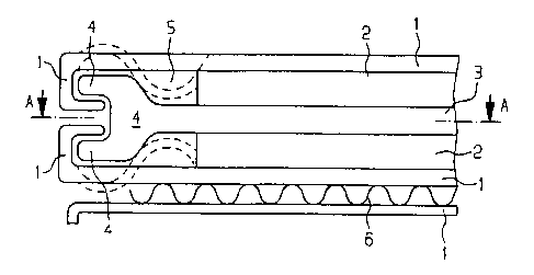
Figure 1 shows a cross section through a fuel cell. The
cell is delimited at the top and bottom by in each case
one terminal plate 1. In the center, it is possible to
see the membrane 3, which has an electrode 2 on both
sides. The electrodes 2 cover only the active surface
of the membrane 3. The cooling channel 6 is shown
between the lower terminal plate 1 and the upper
terminal plate 1 of the next (adjoining) fuel cell. The
edge 4 of the membrane 3 is free of the electrode
coating and has a U-shaped bulge, in which the edges of
the terminal plates 1 are hooked so as to form the edge
seal. The edge 4 is, for example, injection-molded onto
the membrane 3. To improve the sealing, the edge seal
formed from membrane edge 4 and the two terminal plates
1 is latched together in meandering, i . a . curved, form
along the edge, as indicated by dashed lines in Figure
1 and as shown explicitly in Figure 2.
Figure 2 shows a plan view on section A-A from Figure
1. Accordingly, the viewer is looking at the membrane
3, which has not been sectioned through its thickness
as in Figure 1, but rather through its flat area. In
the edge region 7, one is looking at the hooked-in
lower terminal plate 1. The terminal plate 1 is latched
in, in meandering form, i.e. with curved bends, along


CA 02359733 2001-07-26
GR 99 P 1118 - 3a -
the boundary section shown, so that the edge, as
indicated by dashed lines in Figure 1, again and again


CA 02359733 2001-07-26
GR 99 P 1118 - 4 -
latches into the cavity 5 between the active surface
with electrode 2 and the membrane edge 4. The result is
an optimum edge seal.
To produce the fuel cell, the terminal plates 1, the
coated membrane 3 and, if appropriate, the cooling
sheet 6 are placed loosely on top of one another and in
the process are pre-positioned on account of the
geometry of the individual parts. In the unjoined
starting state, the outer edge of the terminal plates 1
is in this case straight . The functioning cell is then
formed by the joining operation of the individual parts
in the form of "latching in" the outez: edge of the
terminal plates 1 in the meandering form shown. In this
way, the positive lock between terminal- plate 1 and
membrane edge 4 allows both gastightness and "stacking"
of the complete cells. The uniform, symmetrical form of
the terminal plates of an individual cell is
maintained.
The mechanical/structural connection of the- two
terminal plates to the membrane during assembly of the
fuel cell results in a seal in the edge region of the
fuel cell, through which gas can be discharged in the
event of excess pressure but which is otherwise sealed
in a gastight manner with respect to the outside.
The invention is suitable for both stationary and
mobile applications of the PEM fuel cell.

Representative Drawing
A single figure which represents the drawing illustrating the invention.
Administrative Status

For a clearer understanding of the status of the application/patent presented on this page, the site Disclaimer , as well as the definitions for Patent , Administrative Status , Maintenance Fee  and Payment History  should be consulted.

Administrative Status

Title Date
Forecasted Issue Date Unavailable
(86) PCT Filing Date 2000-01-11
(87) PCT Publication Date 2000-08-03
(85) National Entry 2001-07-26
Dead Application 2006-01-11

Abandonment History

Abandonment Date Reason Reinstatement Date
2005-01-11 FAILURE TO REQUEST EXAMINATION
2005-01-11 FAILURE TO PAY APPLICATION MAINTENANCE FEE

Payment History

Fee Type Anniversary Year Due Date Amount Paid Paid Date
Registration of a document - section 124 $100.00 2001-07-26
Application Fee $300.00 2001-07-26
Maintenance Fee - Application - New Act 2 2002-01-11 $100.00 2001-12-13
Maintenance Fee - Application - New Act 3 2003-01-13 $100.00 2002-12-11
Maintenance Fee - Application - New Act 4 2004-01-12 $100.00 2003-12-09
Owners on Record

Note: Records showing the ownership history in alphabetical order.

Current Owners on Record
SIEMENS AKTIENGESELLSCHAFT
Past Owners on Record
BRUCKNER, DIETER
KLOKE, WOLFGANG
Past Owners that do not appear in the "Owners on Record" listing will appear in other documentation within the application.
Documents

To view selected files, please enter reCAPTCHA code :


To view images, click a link in the Document Description column. To download the documents, select one or more checkboxes in the first column and then click the "Download Selected in PDF format (Zip Archive)" or the "Download Selected as Single PDF" button.

List of published and non-published patent-specific documents on the CPD .

If you have any difficulty accessing content, you can call the Client Service Centre at 1-866-997-1936 or send them an e-mail at CIPO Client Service Centre.


Document
Description 
Date
(yyyy-mm-dd) 
Number of pages   Size of Image (KB) 
Representative Drawing 2001-11-22 1 9
Abstract 2001-07-26 1 49
Drawings 2001-07-26 1 13
Claims 2001-07-26 1 42
Description 2001-07-26 6 229
Abstract 2001-07-26 1 41
Abstract 2001-07-27 1 10
Cover Page 2001-11-23 1 33
PCT 2001-07-26 9 321
Assignment 2001-07-26 3 142
PCT 2001-07-27 3 133