Note: Descriptions are shown in the official language in which they were submitted.
CA 02360023 2001-10-25
1
AIR-COOLED ELECTRONIC EQUIPMENT ENCLOSED IN A SECURE
CABINET
FIELD OF INVENTION
The invention resided in the field of temperature controlling of electronic
equipment by air flows. In particular, it is directed to an apparatus for and
a
method of air-cooling the electronic equipment located in a secure enclosure.
BACKGROUND OF INVENTION
Telecom service providers request secure cabinets in addition to telecom
switching equipment. As a result of the deregulation of the telecom industry,
which is happening on a global basis, service providers must now open the
doors
of their central offices to their competitors, and consequently security of
their
equipment and integrity of their service is a serious concern to the service
provider.
The-need for secure cabinets to enclose installed telecom equipment is fairly
new
and the market for such cabinets is continually growing.
The growing practice of co=location of telecom equipment from competing
vendors in a common facility has created a need to house telecom equipment in
secure enclosures (cabinets), as a measure to ensure the integrity of service.
For
example, service can not be inadvertently disrupted by craftpersons. There are
a
wide variety of telecom equipment that must be secured for integrity, e.g.,
central
office equipment, switches, routers, mobile switching center to name a few.
Any vendor of high-powered (more than 1kW) electronic equipment will
be faced with the problem of operating in an elevated temperature when
deploying
into closed cabinets. .Power dissipation of modern telecom equipment is
continuously rising, requiring more elaborate cooling mechanisms which are
difficult to incorporate into a closed cabinet.
The know prior art, for example, cabinets taught in published applications
WO 00/21372 and AU 9183401, rely on indirect ventilation to cool installed
electronic equipment. In such a scheme, the installed telecom (electronic)
equipment intakes air from the cabinet interior and exhausts air into the
cabinet
interior. The cabinet employs a separate ventilation scheme to exchange air.
With indirect ventilation, the installed equipment will always see an
elevated ambient temperature inside the cabinet, compared to the air
temperature at
CA 02360023 2001-10-25
2
the cabinet intake. In order to reduce the cabinet interior temperature, some
vendors have advocated placing heat exchangers or air conditioners into
cabinets.
The problem with indirect ventilation in a cabinet is that the electronic
equipment housed within the cabinet is operating in an elevated air
temperature
S relative to the cabinet air intake temperature. With high-powered equipment,
the
temperature rise can be significant (>lSdegC), resulting in a derated
operational
temperature range, (the rate of the temperature range having to be revised).
For
example, if the cabinet internal temperature were operating 1 SdegC above
cabinet
air intake temperature, the typical equipment operating temperature limit of
IO 40degC would have to be derated to ZSdegC when deployed in the cabinet.
This
would greatly increase the chance of a thermal shutdown due to an air-
conditioning
failure within the facility.
The addition of heat exchangers or air conditioners to lower cabinet air
intake temperatures requires significant infrastructure costs to the
installer, and
1S large risks of costly damage due to fluid leakage and cooling equipment
failure.
Telecom service providers are often unwilling to deal with .the additional
cost, risk,
and complexity of adding heat exchangers or air conditioners to their
equipment
installations: Without aii- conditioning, on the other hand, reliability of
service us
affected due to higher equipment temperatures with indirect ventilation.
20 The cabinet fans necessary for the indirect ventilation approach must be
regularly maintained and replaced to ensure continuous operation, requiring
more
elaborate design effort, higher manufacturing cost, and higher maintenance
cost.
Cabinet fans and air conditioners require significant power to operate and are
also
noisy at high speeds necessary for high power. The use of heat exchangers and
air
': 2S conditioners introduces fluids that are hazardous to electronic
equipment in the
event of a leak. Furthermore, cabinets with fans and air conditioners require
regulatory approvals.
SUMMARY OF INVENT10N
30 The invention solves the elevated air temperature problems discussed
above. In accordance with one aspect, the invention solves the problems by
providing a sealed port connecting the telecom eduipment air intake to the
outside
room air.
In a further aspect, the invention relates to a method of providing a direct
3S ambient air flow to an air intake of internal electronic equipment.
CA 02360023 2001-10-25
3
In a yet another aspect, the invention relates to a cabinet for securely
enclosing internal electronic equipment so that human access to the electronic
equipment is prevented or restricted, while providing direct ambient air flow
from
the exterior of the cabinet to an air intake of the electronic equipment.
In still a further aspect, the invention relates to a cabinet securely
enclosing
an internal electronic equipment, the cabinet comprising side panels
preventing
human access to the electronic equipment and.having a substantially air tight
conduit between a port in one of the side panels and an air intake of the
cooling
mechanism of the electronic equipment.
BRIEF DESCRIPTION OF THE DRAWINGS
Figure 1 illustrates schematically a direct ventilation scheme showing
internal equipment, according to one embodiment of the invention.
Figure 2 illustrates an external view of a cabinet according to one
embodiment of the invention.
Figure 3 is a schematic representation of a cabinet door and a snorkel
according to one embodiment of the invention.
Figure 4 is a more detailed illustration of a snorkel according to one
embodiment.
Figure 5 is an exploded view of a snorkel assembly according to one
embodiment.
Figure 6 is a snorkel according to another embodiment of the invention.
DETAILED DESCRIPTION OF PREFERRED EMBODIMENTS OF
INVENTION
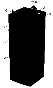
Figure 1 shows a cabinet 10 according to one embodiment of the invention.
The figure also shows in phantom internal electronic equipment 12 on a rack,
together with air intakes 14 on the front side of the rack and air outlets 16
at the
top. The air intakes and outlets are shown in real lines and air flows are
also
shown. Figure 2 shows an external view of a cabinet 10 which has side panels
securely enclosing the internal electronic equipment and preventing or
restricting
in advertent human access fo the equipment. One or more side panels are
provided
with a door or doors which permit necessary internal access. Figure 2 also
shows
ports 20 which are air tightly connected to the air intakes 14 shown in Figure
1.
Instead of internal cabinet air, the air intakes of the internal equipment
take in
CA 02360023 2001-10-25
4
cooler air from the outside of the cabinet. Warm exhaust air from the
electronic
equipment is expelled into the cabinet and out through an opening in the
cabinet
roof. Despite the elevated temperature of the cabinet interior, the electronic
equipment continues to "breathe" fresh cool air from the room ambient, and as
such the internal electronics are not subjected to an elevated temperature
condition.
Figures 3-5 show schematically a sealed port in the cabinet and a coupling
between the air intake of the internal electronic equipment and the sealed
port. The
Figures therefore show a sealed air conduit or snorkel for air external of the
cabinet
from the sealed port to the air intake of the internal equipment, according to
an
embodiment of the invention.
Figure 6 shows another embodiment of the snorkel.
As can be seen in the above discussion; the design of the sealed port on the
cabinet is somewhat dependent upon the internal equipment and its air intakes.
It
is however possible to locate a sealed port on the cabinet liberally in
relation to an
equipment air intake as long as there is an air conduit for substantial amount
of air
flow between them which should be sufficient for a proper operation of the
electronic equipment. The air conduit or snorkel can be formed by rigid
material
or may be made of a flexible material to accommodate relative misalignment or
displacement between the sealed port and the air intake. For example, the
sealed
port may be located lower than the air intake so that air flow by convection
aids the
overall ventilation. The size of the sealed port can also be varied relative
to the
size of the air intake as long as the air flow is sufficient. It is also
possible to
provide air conduits between one or more sealed ports on a cabinet and one or
more air intakes of internal equipment. In other words, an air conduit may
have
one or more branches, provided that each air intake is supplied with a
sufficient
amount of ambient air through one or more sealed ports.
Central offices (COs) typically employ air conditioning equipment to
maintain the ambient air in the CO within a desired temperature range. The
present invention advantageously utilizes the cooled ambient air together with
the
cooling mechanism of the electronic equipment, to provide a secure cabinet
with a
very effective passive cooling scheme. It does not require additional air
conditioners or heat exchangers.
The resistance to the airflow of the exhausting air from the cabinet is very
low, resulting in no need for separate fans in the cabinet, significantly
reducing the
cost of the cabinet (and its maintenance}, and more importantly eliminating
the risk
CA 02360023 2001-10-25
of thermal shutdown due to cabinet fan failure. In this embodiment, the
ventilation
scheme of the cabinet is driven by the fans of the internal electronic
equipment
only.
Since the electronic equipment housed in the cabinet of the invention
5 "breathes" room ambient air, there is no need to Berate the operational
temperature
range of the electronic equipment due to being deployed in this cabinet. Since
there are no fans required, the cost of manufacture and operation of the
cabinet is
minimized, in relation to the prior art cabinets.
Since there are no active components in the cabinet of the invention, the
regulatory approval process is minimized, allowing rapid deployment to world
markets. The cabinet of the invention can also be incorporated to house
existing
equipment designs and installations, allowing the equipment to operate
normally
with no thermal effect due to cabinetization. The cabinet also places no
burden of
additional active cooling devices and their associated fluids on the host
facility.
There will be a competitive advantage to those vendors who do not need to
Berate their operating specifications. There will be a competitive advantage
to
those vendors that supply the most cost-effective cabinet solutions with no
maintenance requirements.