Language selection

Search

Patent 2360104 Summary

Third-party information liability

Some of the information on this Web page has been provided by external sources. The Government of Canada is not responsible for the accuracy, reliability or currency of the information supplied by external sources. Users wishing to rely upon this information should consult directly with the source of the information. Content provided by external sources is not subject to official languages, privacy and accessibility requirements.

Claims and Abstract availability

Any discrepancies in the text and image of the Claims and Abstract are due to differing posting times. Text of the Claims and Abstract are posted:

  • At the time the application is open to public inspection;
  • At the time of issue of the patent (grant).
(12) Patent Application: (11) CA 2360104
(54) English Title: PAN LINER
(54) French Title: DOUBLURE DE NACELLE
Status: Deemed Abandoned and Beyond the Period of Reinstatement - Pending Response to Notice of Disregarded Communication
Bibliographic Data
(51) International Patent Classification (IPC):
  • A47J 36/00 (2006.01)
  • A47J 27/00 (2006.01)
  • A47J 36/02 (2006.01)
  • A47J 37/01 (2006.01)
(72) Inventors :
  • GREENFIELD, MICHAEL L. (United States of America)
  • GREENFIELD, LAWRENCE (United States of America)
(73) Owners :
  • CONNECTICUT PACKAGING MATERIALS INC.
(71) Applicants :
  • CONNECTICUT PACKAGING MATERIALS INC. (United States of America)
(74) Agent: NORTON ROSE FULBRIGHT CANADA LLP/S.E.N.C.R.L., S.R.L.
(74) Associate agent:
(45) Issued:
(22) Filed Date: 2001-10-24
(41) Open to Public Inspection: 2002-04-24
Examination requested: 2006-10-24
Availability of licence: N/A
Dedicated to the Public: N/A
(25) Language of filing: English

Patent Cooperation Treaty (PCT): No

(30) Application Priority Data:
Application No. Country/Territory Date
60/242,972 (United States of America) 2000-10-24

Abstracts

English Abstract


A contoured pan liner and method of making a pan liner is provided, the pan
liner including a first liner side panel having a first upper edge; a second
liner side
panel having a second upper edge; and at least one scam joining the first and
second
side panels, the first side panel, second side panel and at least one seam
forming an
interior region having an opening along the first and second upper edges, and
wherein
at least a portion of the at least one scam defines an arcuate path along at
least a lower
portion of the interior region.


Claims

Note: Claims are shown in the official language in which they were submitted.

6
CLAIMS
1. A contoured pan liner comprising:
a first liner side panel having a first upper edge;
a second liner side panel having a second upper edge; and
at least one scam joining the first and second side panels, the first side
panel, second side panel and at least one seam foaming an inferior region
having an
opening along the first and second upper edges, and wherein at least a portion
of the at
least one seam defines an arcuate path along at least a lower portion of the
interior
region.
2. The contoured pan liner in accordance with claim 1, wherein the opening
is configured to engage the top edge of a pan.
3. The contoured pan liner in accordance with claim 1, wherein the liner is
symmetric with respect to the at least one first seal.
4. The contoured pan liner in accordance with claim 1, further comprising a
second scam joining the first and second side panels, the second scam defining
an
arcuate path along at least a lower portion of the interior region.
5. The contoured pan liner in accordance with claim 1, wherein the liner is
contoured such that the liner is configured to be substantially coextensive
with the
internal dimensions of a pan.
6. The contoured pan liner in accordance with claim 1, wherein the panels
comprise a non-heat scalable temperature resistant polyester outer laminate
layer and a
heat scalable polyolefin inner laminate layer.

7
7. The contoured pan liner in accordance with claim 6, wherein the inner
laminate layer is a polyethylene or polypropylene material.
8. The contoured pan liner in accordance wish claim 4, further comprising a
lower fold line between first and second seams.
9. The contoured pan liner in accordance with claim 1, further comprising a
fold line on at least a portion of the liner between the upper edges and the
at least one
seam.
10. A temperature resistant, food compatible pan liner, comprising:
a first liner side panel having a first upper edge;
a second liner side panel having a second upper edge, the second side
panel sealed to the first side panel along at least one seam, the first side
panel, second
side panel and at least one scam forming an interior region having an opening
along the
lust and second upper edges, and wherein at least one of the first and second
side
panels comprises a plastic laminate, comprising a heat sealable polyolefin
inner layer
and a non-heat scalable, temperature resistant material exterior layer.
11. The temperature resistant, food compatible pan liner in accordance with
claim 10, wherein the opening is configured to engage the top edge of a pan.
12. The temperature resistant, food compatible pan liner in accordance with
claim 10, wherein the liner is symmetric with respect to the at least one
first seal.
13. The temperature resistant, food compatible pan liner in accordance with
claim 10, further comprising a second seam joining the first and second side
panels, the
second seam defining an arcuaie path along at least a lower portion of the
interior
region.

14. The temperature resistant, food compatible pan liner in accordance with
claim 10, wherein the liner is contoured such that the liner is configured to
be
substantially coextensive with the internal dimensions of a pan.
15. The temperature resistant, food compatible pan liner in accordance with
claim 13, further comprising a lower fold lint between first and second seams.
16. The temperature resistant, food compatible pan liner in accordance with
claim 10, further comprising a fold line on at least a portion of the liner
between the
upper edges and the at least one seam.
17. A contoured pan liner, comprising:
a tube of a plastic laminate liner material; and
at least one seam on at least a bottom portion of the tube, wherein the
tube and the at least one seam defines an interior region, and wherein at
least a portion
of the at least one scam defines an arcuate path along at least a lower
portion of the
interior region.
18. The contoured pan liner in accordance with claim 17, wherein the liner
is symmetric with respect to the at least one first seam.
19. The contoured pan liner in accordance with claim 17, further comprising
a second seam defining an arcuate path along at least a lower portion of the
interior
region.
20. The contoured pan liner in accordance with claim 17, wherein the liner
is contoured such that the liner is configured to be substantially coextensive
with the
internal dimensions of a pan.

9
21. The contoured pan liner in accordance with claim 17, wherein the tube
comprises a non-heat scalable temperature resistant polyester outer laminate
layer and a
heat sealable polyoletin inner laminate layer.
22. The contoured pan liner in accordance with claim 21, wherein the inner
layer is a polyethylene or polypropylene material.
23. The contoured pan liner in accordance with claim 19, further comprising
a lower fold line between first and second seams.
24. The contoured pan liner in accordance with claim 17, further comprising
a fold line on at least a portion of the liner between an upper edge of the
tube and the at
last one seam.
25. A method of manufacturing a pan liner, comprising:
laminating a heat sealable holyolefin inner layer and a non-heat sealable,
temperature resistant material exterior layer to form at least one panel;
forming an interior region between two panel surfaces, comprising
forming at least one seam, wherein the at least one scam is arcuate along a
path on at
least a lower portion of the interior region.
26. The method of manufacturing a pan liner in accordance with claim 25,
wherein the at least one panel is a tubular panel, and wherein the at least
one seam is
fonncd at one end of the tubular panel to form the interior region.
27. The method of manufacturing a pan liner in accordance with claim 25,
wherein the at least one panel is folded onto itself, and wherein the at least
one seam is
formed ott a portion of the folded panel to form the interior region.

10
28. The method of manufacturing a pan liner in accordance with claim 25,
wherein a first and second panels are stacked, and wherein the at least one
scam is
formed on the slacked first and second panels to form the interior region.
29. The method of manufacturing a pan liner in accordance with claim 25,
wherein at least one seam is heat sealed.

Description

Note: Descriptions are shown in the official language in which they were submitted.


CA 02360104 2001-10-24
1
PAN LINER
CROSS REFERENCE TO RLLATED APPLICATIONS
the present application claims the priority of United Stales Provisional
Application Serial Number 60/242,972, filed October 24, 2001, the entire
contents of
which arc specifical ly incorporated herein by reference.
FIEi,D
The invention relates to a liner for a pan and more particularly to a
specially
shaped bag used to line a food service pan.
BACKGTZOUND
The food prcpaxation industry relies heavily on non-disposable cookware for
both hot and cold food preparation. Such cookware is typically used, re-used,
scrubbed
and washed several times during a workday. In fact, many restaurants maintain
a staff
of employees whose primary responsibilities are scrubbing and washing such
cookware.
Many restaurants consider the expenses associated with hiring and maintaining
the
I 5 staff of employees responsible for scrubbing, with purchase of cleaning
supplies and
hot water, with maintaining a scrubbing station within the restaurant, and
with waste
caused by either scorching of the food, lack of convenient storage or food
which carrot
easily be removed from the edges of the cookware to be necessary and
unavoidable
expenses.
What is needed in the art is a low cost solution to the problems associated
with
cleaning soiled cookware as they are laid out above.

CA 02360104 2001-10-24
z
SUMMARY
The present contoured pan liner overcomes and alleviates the above and other
problems in the apt by providing a first liner side panel having a first upper
edge; a
second liner side panel having a second upper edge; and at least one seam
joining the
first and second side panels, the first side panel, second side panel and at
least one seam
forming an interior region having an opening along the rrst and second upper
edges,
and wherein at least a Portion of the ai Ieast one scam defines an arcuate
path along at
least a lower portion of the interior regrion.
In an exemplary embodiment, the liner is generally contoured to lit within an
article of cookware. In another exemplary embodiment, the liner is
substantially
contoured to the shape of an article of cookware. In another exemplary
embodiment, at
least two scams provided along an interior region of the liner generally hacc
arcuate
paths along at least a lower portion of the interior region.
Further, in another exemplary embodiment, the liner comprises a non-heat
sealable temperature resistant polyester as an outer laminate layer and a heat
sealable
polyolefin, such as a polyethylene or polypropylene, as an inner laminate
layer.
BRIEF DESCRIPTION OF THE DRAWINGS
Referring now to the drawings wherein like elements are nutnbercd alike in the
several F1GURES:
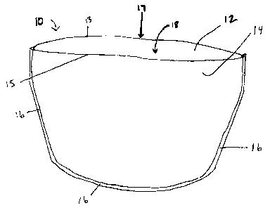
FIGURL 1 is a perspective vices of an exemplary embodiment of a contoured
pan liner;
FIGURC 2 is a Perspective view of an exemplary embodiment of a contoured
Pan liner in position within an exemplary pan;
FIGURE 3 is a perspective view of another exemplary embodiment of a
2~ contoured pan liner; and
FIGU12F 4 is a perspective view of another exemplary embodiment of a
contoured pan liner,

CA 02360104 2001-10-24
3
DETATLED DESCRTPTION
Referring to FIGURE T; an exemplary embodiment of a contoured pan liner is
shovm generally at 10. The exemplary contoured pan liner comprises first and
second
side panels 12, 14 sealed along a seam 16. The panels 12, 14 are illusti~atcd
as being of
similar site and shape, such that the contoured pan liner is generally
symmetric with
respect to the seam 16. An interior region 18 is defined by the first and
second side
panels 12, 14 and the scam 16. The upper edges 13, 15 of the first and second
panels
12, 14 define an opening 17 in the liner. In the illustrated embodiment, the
scaled
contoured seam 1G extends in a continuous arcuate path around the interior
region 18 of
panels 12, 14. The seals may be formed by any method known in the art, but are
preferably heat-scaled.
Referring now to FIGURE 2, an exemplary contoured pan Iincr is generally
shown at 20 disposed within a pan, shown generally at 24. The contoured seam
1G,
extends from within the pan 24up the inner sides 2G (not shown), 28 of the pan
24, and
over the top edge 30 of the pm 34. Thus, the upper edges 13, 1 S of the first
anti second
side panels 12, 14 are illustrated as configured to engage the top of the pan
34.
With reference to FIGURE 3, another exemplary embodiment of a contoured
pan liner is illustrated generally al 40, In the illustrated embodiment, first
and second
panels 42, 44 are sealed alonb first and second scams 46, 48 acid along a
lower fold line
50. 1.'he first and second panels 42, 44, first and second seams 4G, 48 and
lower fold
line 50 define an interior region, shown generally at 52. First and second
upper edges
43, 45 of first a.nd second panels 42, 44 define an opening, shown scnerally
at 54.
With reference to FIGURE 4, another exemplary embodiment of a contoured
pan liner is illustrated generally at G0. The exemplary contoured pan litter
comprises a
tube 62 of liner material having an upper edge 64 defining an opening, shown
generally
at GG. The tube is scaled at a lower end portion G8 by a seam 70. The seam 70
and the
tube G2 define an interior region, shown generally at 72. The scam 70 traces a
generally
arcuate path along a lower portion of the interior space 72.
In one exemplary embodiment, the materials employed for construction of the
pan liner include plastic laminates. That is, the panels comprise at least two
layers of
plastic in which may be joined or laminated by conventional methods. In one

CA 02360104 2001-10-24
4
embodiment, the outer Layer is a non-heat scalable material capable
ofrcsisting
sustained temperatures of up to about 200 degrees Faluenheit, such as those
temperatures which arc used for repeating of foods and service presentation of
foods,
rather than those temperatures required for cooking of foods. In another
exemplary
embodiment, the outer layer is a non-heat sealable material capable of
resisting
sustained temperatures of up to and above 400 degrees rahrcnheit, such as the
temperatures which may typically be encountered in the cooking of foods. In
another
exemplary embodiment, the outer layer is a non-heat scalable, low to high
temperature,
heat resistant material, such as a polyester material. In another exemplary
e~nbodimenl,
the outer laminate layer is a material similar to those types of heat
resistant materials
sold under the trade name Mylar.
1n another embodiment, the inner layer is heat sealable material that will not
degrade in low to high temperature environments and that is safe for food
contact. The
heat scalable materials of the iniicr layer may provide an airtight and wafer
tight barrier
along the scams of the pan liner. Such inner layer also need not directly
contact the
heated source, and as such it may be a material having a lower temperature
resistance
(and thus, lower cost) than the outer layer. In one embodiment, the inner
layer is a heat-
sealable polyolcfin material. bi another embodiment, the inner layer is a
polypropylene
or polyethylene material.
The liner, when expanded, defines an interior region, which provides a depth
suffcicnt to fit into the bottom of a pan. The laminate constriction and
contour
gCOIIlCtfy provide the ability to neatly hold any remaining material when the
litter is
removed from the pan. In one embodiment, the dimensions of the interior region
arc
SltCh that when the pan liner is placed witlun a pan, the interior region is
substantially
contoured to the pan such that free space between the liner and the pan is
ntinimiied
and such that bunclung of the material (where the material is too large for
the pan) is
minimized. 'This close fit provides for maximum volume of the liner and paai
system
and clean operation of the system for food service.
The illustrated seamins configurations illustrated by the exemplary embodiment
as shown in FICiURF,S 1-4, wherein at least one seam is provided and wherein
the at
least one scam defines an arcuatp path along at least a lower portion of the
vitcrior

CA 02360104 2001-10-24
region, also plays an important role in minimizing waste by eliminating
troublesome
corners along the seams.
F1GURE 1 illustrates an exemplary liner independently from the pan. As can be
seen, the contoured searn 16 traces a generally arcuatc path along a lower
portion of the
interior space 18. Thus, food carmot accrue in areas inaccessible to a spoon
or other
instrument. This exemplary liner not only eliminates waste by virtue of the
fully
expanded intc;rior space I8 geometry, but also provides for easy food removal
from the
liner whether the liner is fully open or partially collapsed.
Lining such cookware adv.~.ntageously provides a sanitary cooking and/or
serving surface. Lining pans is an efficient means of food service as it
removes the
need for washing pans, eliminating the cost of washing and the time a pan is
made
unavailable while it is being washed. Pans can be immediately re-lined and
rcttsed.
The present pan liner also provides an advantageous seaming conrguralion,
including
an arcuate scam path along at least a lower potrtion of the interior region,
for facilitating
food removal whether the liner is expanded or partially collapsed. ~'he
present pan liner
also advantageously provides a laminate material tailored to reduce costs and
to provide
exterior heat resistance coupled with interior sealing and food compatibility
at elevated
tetnperahtres.
Although the invention has been shown and described with respect to exeioplary
embodiments thereof, it should be understood by those skilled in the aat that
various
changes, omissions, and additions may be made thereto, without departing from
the
spirit and scope of the invention.

Representative Drawing
A single figure which represents the drawing illustrating the invention.
Administrative Status

2024-08-01:As part of the Next Generation Patents (NGP) transition, the Canadian Patents Database (CPD) now contains a more detailed Event History, which replicates the Event Log of our new back-office solution.

Please note that "Inactive:" events refers to events no longer in use in our new back-office solution.

For a clearer understanding of the status of the application/patent presented on this page, the site Disclaimer , as well as the definitions for Patent , Event History , Maintenance Fee  and Payment History  should be consulted.

Event History

Description Date
Application Not Reinstated by Deadline 2010-09-20
Inactive: Dead - No reply to s.30(2) Rules requisition 2010-09-20
Deemed Abandoned - Failure to Respond to Maintenance Fee Notice 2009-10-26
Inactive: Abandoned - No reply to s.30(2) Rules requisition 2009-09-18
Inactive: S.30(2) Rules - Examiner requisition 2009-03-18
Letter Sent 2006-11-07
All Requirements for Examination Determined Compliant 2006-10-24
Request for Examination Requirements Determined Compliant 2006-10-24
Request for Examination Received 2006-10-24
Inactive: IPC from MCD 2006-03-12
Inactive: Office letter 2006-01-09
Inactive: Delete abandonment 2006-01-06
Deemed Abandoned - Failure to Respond to Maintenance Fee Notice 2005-10-24
Letter Sent 2002-05-23
Application Published (Open to Public Inspection) 2002-04-24
Inactive: Cover page published 2002-04-23
Amendment Received - Voluntary Amendment 2002-04-03
Inactive: Single transfer 2002-04-03
Inactive: First IPC assigned 2002-01-04
Inactive: IPC assigned 2002-01-04
Inactive: Courtesy letter - Evidence 2001-11-13
Inactive: Filing certificate - No RFE (English) 2001-11-08
Filing Requirements Determined Compliant 2001-11-08
Application Received - Regular National 2001-11-08

Abandonment History

Abandonment Date Reason Reinstatement Date
2009-10-26
2005-10-24

Maintenance Fee

The last payment was received on 2008-10-15

Note : If the full payment has not been received on or before the date indicated, a further fee may be required which may be one of the following

  • the reinstatement fee;
  • the late payment fee; or
  • additional fee to reverse deemed expiry.

Patent fees are adjusted on the 1st of January every year. The amounts above are the current amounts if received by December 31 of the current year.
Please refer to the CIPO Patent Fees web page to see all current fee amounts.

Fee History

Fee Type Anniversary Year Due Date Paid Date
Application fee - standard 2001-10-24
Registration of a document 2002-04-03
MF (application, 2nd anniv.) - standard 02 2003-10-24 2003-10-08
MF (application, 3rd anniv.) - standard 03 2004-10-25 2004-10-06
MF (application, 4th anniv.) - standard 04 2005-10-24 2005-10-24
MF (application, 5th anniv.) - standard 05 2006-10-24 2006-10-24
Request for examination - standard 2006-10-24
MF (application, 6th anniv.) - standard 06 2007-10-24 2007-10-02
MF (application, 7th anniv.) - standard 07 2008-10-24 2008-10-15
Owners on Record

Note: Records showing the ownership history in alphabetical order.

Current Owners on Record
CONNECTICUT PACKAGING MATERIALS INC.
Past Owners on Record
LAWRENCE GREENFIELD
MICHAEL L. GREENFIELD
Past Owners that do not appear in the "Owners on Record" listing will appear in other documentation within the application.
Documents

To view selected files, please enter reCAPTCHA code :


To view images, click a link in the Document Description column. To download the documents, select one or more checkboxes in the first column and then click the "Download Selected in PDF format (Zip Archive)" or the "Download Selected as Single PDF" button.

List of published and non-published patent-specific documents on the CPD .

If you have any difficulty accessing content, you can call the Client Service Centre at 1-866-997-1936 or send them an e-mail at CIPO Client Service Centre.


Document
Description 
Date
(yyyy-mm-dd) 
Number of pages   Size of Image (KB) 
Representative drawing 2002-01-30 1 6
Abstract 2001-10-23 1 13
Description 2001-10-23 5 209
Claims 2001-10-23 5 135
Drawings 2001-10-23 4 35
Description 2002-04-02 5 227
Abstract 2002-04-02 1 15
Claims 2002-04-02 5 151
Drawings 2002-04-02 4 43
Filing Certificate (English) 2001-11-07 1 164
Courtesy - Certificate of registration (related document(s)) 2002-05-22 1 114
Reminder of maintenance fee due 2003-06-25 1 106
Reminder - Request for Examination 2006-06-27 1 116
Acknowledgement of Request for Examination 2006-11-06 1 178
Courtesy - Abandonment Letter (Maintenance Fee) 2009-12-20 1 173
Courtesy - Abandonment Letter (R30(2)) 2009-12-13 1 164
Correspondence 2001-11-07 1 24
Correspondence 2006-01-08 1 14