Language selection

Search

Patent 2360182 Summary

Third-party information liability

Some of the information on this Web page has been provided by external sources. The Government of Canada is not responsible for the accuracy, reliability or currency of the information supplied by external sources. Users wishing to rely upon this information should consult directly with the source of the information. Content provided by external sources is not subject to official languages, privacy and accessibility requirements.

Claims and Abstract availability

Any discrepancies in the text and image of the Claims and Abstract are due to differing posting times. Text of the Claims and Abstract are posted:

  • At the time the application is open to public inspection;
  • At the time of issue of the patent (grant).
(12) Patent Application: (11) CA 2360182
(54) English Title: CONVERSION OF STANDARD CLASS A GROUND-FAULT CIRCUIT INTERRUPTERS, (GFCI), TO A CLASS A GROUND-FAULT CIRCUIT INTERRUPTER WITH OPEN NEUTRAL PROTECTION
(54) French Title: CONVERSION DE DISJONCTEURS DIFFERENTIELS STANDARD DE CLASSE A EN DES DISJONCTEURS DIFFERENTIELS DE CLASSE A AVEC PROTECTION DE LA CONTINUITE DU CIRCUIT NEUTRE
Status: Deemed Abandoned and Beyond the Period of Reinstatement - Pending Response to Notice of Disregarded Communication
Bibliographic Data
(51) International Patent Classification (IPC):
  • H01H 83/02 (2006.01)
  • H02H 03/33 (2006.01)
(72) Inventors :
  • DUVE, JEFF (United States of America)
(73) Owners :
  • COOPER TECHNOLOGIES COMPANY
(71) Applicants :
  • COOPER TECHNOLOGIES COMPANY (United States of America)
(74) Agent: FINLAYSON & SINGLEHURST
(74) Associate agent:
(45) Issued:
(22) Filed Date: 2001-10-24
(41) Open to Public Inspection: 2002-06-13
Examination requested: 2001-12-21
Availability of licence: N/A
Dedicated to the Public: N/A
(25) Language of filing: English

Patent Cooperation Treaty (PCT): No

(30) Application Priority Data:
Application No. Country/Territory Date
09/737,273 (United States of America) 2000-12-13

Abstracts

English Abstract


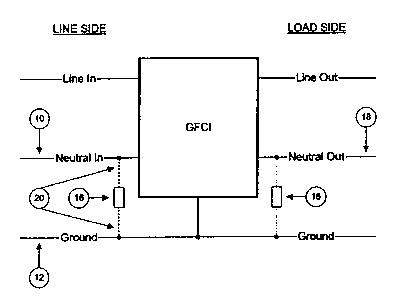
The present invention concerns an improved ground fault circuit
interrupt outlet. The device includes a voltage sensitive device which is
capable of conducting current at a predetermined voltage. The voltage
sensitive device is electrically connected between a ground on the ground
fault circuit interrupt outlet and a neutral located on the ground fault
circuit interrupt outlet. arranging the device in this manner converts
the ground fault circuit interrupt outlet into a ground fault circuit
interrupt
with open neutral protection.


Claims

Note: Claims are shown in the official language in which they were submitted.


What is claimed is:
1. An improved ground fault circuit interrupt outlet
comprising:
a voltage sensitive device which is capable of conducting
current at a predetermined voltage;
said voltage sensitive device electrically connected between a
ground on said ground fault circuit interrupt outlet and a neutral located on
said ground fault circuit interrupt outlet, whereby said ground fault circuit
interrupt outlet is converted into a ground fault circuit interrupt with open
neutral protection.
2. The device of claim 1 wherein said neutral is located on a
line side of said ground fault circuit interrupt outlet.
3. The device of claim 1 wherein said neutral is located on
said load side of said ground fault circuit interrupt outlet.
4. The device of claim 1 wherein said voltage sensitive device
is a diac.
S. The device of claim 1 wherein said voltage sensitive device
is a triac.
6. The device of claim 1 wherein said voltage sensitive device
is a SCR.
7. The device of claim 1 wherein said voltage sensitive device
is a SIDAC.
6

8. The device of claim 1 wherein said voltage sensitive device
is a bipolar TVS.
9. The device of claim 1 wherein said voltage sensitive device
is back to back zener diodes.
10. An outlet having a ground fault circuit interrupt circuitry
comprising:
an-electrical pathway in communication with a neutral line and
a ground line;
said pathway conducts current to said GFCI circuitry in the
event of a break in said neutral line.
11. The device of claim 10 wherein said electrical pathway
includes a voltage sensitive device.
12. The device of claim 10 wherein said neutral is located on
a line side of said ground fault circuit interrupt outlet.
13. The device of claim 10 wherein said neutral is located on
said load side of said ground fault circuit interrupt outlet.
14. The device of claim 10 wherein said voltage sensitive
device is a diac.
15. The device of claim 10 wherein said voltage sensitive
device is a triac.
16. The device of claim 10 wherein said voltage sensitive
device is a SCR.
7

17. The device of claim 10 wherein said voltage sensitive
device is a SIDAC.
18. The device of claim 10 wherein said voltage sensitive
device is a bipolar TVS.
19. The device of claim 10 wherein said voltage sensitive
device is back to back zener diodes.

Description

Note: Descriptions are shown in the official language in which they were submitted.


CA 02360182 2001-10-24
CONVERSION OF STANDRAD CLASS A GROUND-FAULT CIRCUIT
INTERRUPTERS, (GFCI), TO A CLASS A GROUND-FAULT CIRCUIT
INTERRUPTER WITH OPEN NEUTRAL PROTECTION
Background of the Invention
A ground-Fault Circuit-Interrupter (hereby referred to as GFCI) is a
device that is intended to reduce the chance of accidental electrocution by
interrupting the power line, when the difference in current between the Line
_ (the black wire) and Neutral_(the white wire) is greater than a
predeteiznined
level as set by Underwriter's Laboratories ("UL") in UL943. When properly
connected, a standard GFCI will protect against any Line-to-Earth Ground
faults, thus protecting the end user from potentially fatal electrocution. The
standard Class A GFCI was originally intended for use in wall mount
applications near any potential ground fault locations such as bathrooms,
kitchen counter-tops etc. In order to pass inspection, all outlets are to be
electrically tested to ensure proper connection. Since the wiring in the walls
does not move, the probability of a loose or broken connection after testing
is unlikely. The success of the in-wall GFCI has prompted its use in other
alternate locations. One of the prime candidates for a GFCI is its use on the
end of an extension cord. The problem with an extension cord is that it is
exposed to potential damage, which may break some of the wires in the
cord, and thus, render the GFCI inoperative. This is so because the
standard Class A GFCI utilizes the power from Line to Neutral in order to
operate the unit. Should the Neutral connection be severed, the standard
GFCI will no longer function. In order to address this issue, UL now
1

CA 02360182 2001-10-24
ATTORNEY
DOCKET NO. 3259
requires, in UL153 for Portable Electric Lamps, that the Class A GFCI
incorporate "open neutral protection." This provision protects against only a
broken Neutral wire from disabling the GFCI. The "open neutral provision"
will not protect against both the Open Neutral and Open Earth Ground
failure mode.
Summar9 of the Invention
Current Open Neutral protection is presently being provided by either
an external relay that is powered by the Line-to-Neutral Voltage or by
constructing a custom GFCI with an intrinsic relay/circuit breaker
combination. Both solutions incorporate another magnetic circuit that
tends to either take up more space or impact on product cost.
The major problem with the current standard Class A GFCI is that it
requires power from Line to Neutral in order to function. When the Neutral
connection is broken, the GFCI no longer has the energy to function. From
an ideal electrical point of view, the potential difference between the
Neutral
and Earth Ground is Zero. In the real world, however, it tends to be on the
order of a couple of Volts, depending on Neutral current loss. When the
Neutral line is disconnected, it is no longer capable of sinking any current,
so if a load were connected, it would match Line potential. Based on this, a
Voltage sensitive device/circuit could be placed between Neutral and Earth
Ground such that if the potential should exceed a set point, the device
2

CA 02360182 2001-10-24
ATTORNEY
DOCHET NO. 3259
would start to conduct current, thus pulling the open Neutral's potential
closer to the potential of Earth Ground. By pulling the open Neutral-to-
Earth Ground, the GFCI will then have adequate power to properly function.
One such voltage sensitive device that could be utilized is a DAIC, which
does not conduct significant current until a threshold Voltage is reached.
The Voltage sensitive device could be placed either on the Neutral on the
Line input fide 'or the Neutral on the Load Output Side to offer adequate
open Neutral protection. Ideally the Voltage sensitive device/circuit should
be placed on the Load side since the device could fail, thus triggering the
GFCI and therefore offer improved fail-safe protection. Examples. of other
Voltage sensitive devices/circuits that may be used include, but are not
limited to, the following: DIAC, TRIAC, SCR, SIDAC, Bipolar TVS, back-to-
back Zener diodes and any other Voltage sensitive devices/circuits.
Descriptioa of the Drawings
These and other features, objects and advantages of the present
invention will become apparent from the following description and drawings
wherein like reference numerals represent like elements in several views,
and in which:
FIGURE 1 is a perspective view of one embodiment of the present
invention.
3

CA 02360182 2001-10-24
ATTORNEY
DOCKET NO. 3259
Description of the Preferred Embodiment
Set forth below is a description of what are currently believed to be
the preferred embodiments or best examples of the invention claimed.
Future and present alternatives and modifications to the preferred
_ embodiments are contemplated. Any alternates or modifications in which
insubstantial changes in function, in purpose, in structure or in result are
intended to_be-~covered by the claims of this patent.
The present invention, as explained above, is an economical way in
which to convert a standard class A GFCI outlet into an outlet GFCI with
open neutral protection. As shown in Figure 1, this may be accomplished
by forming an electrical pathway 20 between neutral 10 on the line side and
ground 12 of GFCI outlet 14. Positioned between neutral 10 and ground 14
on pathway 20 is a voltage sensitive device 16 which is capable of
conducting current at a predetermined voltage. Of course, neutral 18 on
the load side may be used as well instead of neutral 10.
Examples of voltage sensitive devices or circuits that may be used
with the present invention include, but are not limited to, triac, diac, SCR,
SIDAC, Bipolar TVS, back to back zener diodes, and a microprocessor.
In use, configuring a standard Class A GFCI in the manner described
above, the GFCI will have open neutral protection in the event of a break in
the neutral line which would result in a loss of power to the GFCI circuitry,
which is well known to those of skill in the art. The present invention
4

CA 02360182 2001-10-24
ATTORNEY
DOCKET NO. 3259
provides an electrical pathway which resupplies power to the GFCI circuitry
by placing a voltage sensitive device or circuit between the neutral and
ground which opens at a predetermined voltage level which is adapted to be
exceeded in the event of a line break in the neutral. This configuration uses -
the low voltage present in the neutral to supply power to the GFCI circuitry.
While the preferred embodiments of the present invention have ~beeri
illustrated and vescribed, it will be understood by those of ordinary skill in
the
art that changes and other modifications can be made without departing from
the invention in its broader aspects. Various features of the present
invention
are set forth in the following claims. ,
5

Representative Drawing
A single figure which represents the drawing illustrating the invention.
Administrative Status

2024-08-01:As part of the Next Generation Patents (NGP) transition, the Canadian Patents Database (CPD) now contains a more detailed Event History, which replicates the Event Log of our new back-office solution.

Please note that "Inactive:" events refers to events no longer in use in our new back-office solution.

For a clearer understanding of the status of the application/patent presented on this page, the site Disclaimer , as well as the definitions for Patent , Event History , Maintenance Fee  and Payment History  should be consulted.

Event History

Description Date
Application Not Reinstated by Deadline 2006-09-01
Inactive: Dead - No reply to s.30(2) Rules requisition 2006-09-01
Inactive: IPC from MCD 2006-03-12
Deemed Abandoned - Failure to Respond to Maintenance Fee Notice 2005-10-24
Inactive: Abandoned - No reply to s.30(2) Rules requisition 2005-09-01
Inactive: S.30(2) Rules - Examiner requisition 2005-03-01
Application Published (Open to Public Inspection) 2002-06-13
Inactive: Cover page published 2002-06-12
Letter Sent 2002-01-25
Request for Examination Requirements Determined Compliant 2001-12-21
All Requirements for Examination Determined Compliant 2001-12-21
Request for Examination Received 2001-12-21
Inactive: First IPC assigned 2001-12-14
Inactive: Filing certificate - No RFE (English) 2001-11-09
Letter Sent 2001-11-09
Application Received - Regular National 2001-11-08

Abandonment History

Abandonment Date Reason Reinstatement Date
2005-10-24

Maintenance Fee

The last payment was received on 2004-09-21

Note : If the full payment has not been received on or before the date indicated, a further fee may be required which may be one of the following

  • the reinstatement fee;
  • the late payment fee; or
  • additional fee to reverse deemed expiry.

Patent fees are adjusted on the 1st of January every year. The amounts above are the current amounts if received by December 31 of the current year.
Please refer to the CIPO Patent Fees web page to see all current fee amounts.

Fee History

Fee Type Anniversary Year Due Date Paid Date
Application fee - standard 2001-10-24
Registration of a document 2001-10-24
Request for examination - standard 2001-12-21
MF (application, 2nd anniv.) - standard 02 2003-10-24 2003-10-15
MF (application, 3rd anniv.) - standard 03 2004-10-25 2004-09-21
Owners on Record

Note: Records showing the ownership history in alphabetical order.

Current Owners on Record
COOPER TECHNOLOGIES COMPANY
Past Owners on Record
JEFF DUVE
Past Owners that do not appear in the "Owners on Record" listing will appear in other documentation within the application.
Documents

To view selected files, please enter reCAPTCHA code :


To view images, click a link in the Document Description column. To download the documents, select one or more checkboxes in the first column and then click the "Download Selected in PDF format (Zip Archive)" or the "Download Selected as Single PDF" button.

List of published and non-published patent-specific documents on the CPD .

If you have any difficulty accessing content, you can call the Client Service Centre at 1-866-997-1936 or send them an e-mail at CIPO Client Service Centre.


Document
Description 
Date
(yyyy-mm-dd) 
Number of pages   Size of Image (KB) 
Representative drawing 2002-02-10 1 6
Description 2001-10-23 5 193
Abstract 2001-10-23 1 21
Drawings 2001-10-23 1 10
Claims 2001-10-23 3 73
Courtesy - Certificate of registration (related document(s)) 2001-11-08 1 113
Filing Certificate (English) 2001-11-08 1 164
Acknowledgement of Request for Examination 2002-01-24 1 178
Reminder of maintenance fee due 2003-06-25 1 106
Courtesy - Abandonment Letter (R30(2)) 2005-11-09 1 167
Courtesy - Abandonment Letter (Maintenance Fee) 2005-12-18 1 174