Language selection

Search

Patent 2360192 Summary

Third-party information liability

Some of the information on this Web page has been provided by external sources. The Government of Canada is not responsible for the accuracy, reliability or currency of the information supplied by external sources. Users wishing to rely upon this information should consult directly with the source of the information. Content provided by external sources is not subject to official languages, privacy and accessibility requirements.

Claims and Abstract availability

Any discrepancies in the text and image of the Claims and Abstract are due to differing posting times. Text of the Claims and Abstract are posted:

  • At the time the application is open to public inspection;
  • At the time of issue of the patent (grant).
(12) Patent: (11) CA 2360192
(54) English Title: A PIPE ASSEMBLY AND LUBRICATING METHOD
(54) French Title: TUYAUTERIE ET METHODE DE LUBRIFICATION
Status: Term Expired - Post Grant Beyond Limit
Bibliographic Data
(51) International Patent Classification (IPC):
  • E21B 21/10 (2006.01)
  • E21B 34/00 (2006.01)
  • E21B 34/06 (2006.01)
(72) Inventors :
  • MURRAY, GEOFFREY NEIL (United States of America)
(73) Owners :
  • WEATHERFORD TECHNOLOGY HOLDINGS, LLC
(71) Applicants :
  • WEATHERFORD TECHNOLOGY HOLDINGS, LLC (United States of America)
(74) Agent: MARKS & CLERK
(74) Associate agent:
(45) Issued: 2008-06-10
(86) PCT Filing Date: 2000-01-07
(87) Open to Public Inspection: 2000-07-20
Examination requested: 2002-10-29
Availability of licence: N/A
Dedicated to the Public: N/A
(25) Language of filing: English

Patent Cooperation Treaty (PCT): Yes
(86) PCT Filing Number: PCT/GB2000/000029
(87) International Publication Number: WO 2000041487
(85) National Entry: 2001-07-10

(30) Application Priority Data:
Application No. Country/Territory Date
333681 (New Zealand) 1999-01-11

Abstracts

English Abstract


A pipe assembly (5) for use in a wellbore (3) having a plurality of outlets
(6) positioned
about the periphery of the pipe at longitudinally spaced apart intervals for
allowing fluid to
pass from the interior to the exterior of the pipe.


French Abstract

Cette invention a trait à une tuyauterie (5), utilisable dans un forage (3), possédant plusieurs orifices de sortie (6) disposés, sur sa périphérie, à intervalle les uns des autres, sur le plan longitudinal, cet agencement permettant à un fluide de passer de l'intérieur vers l'extérieur de la tuyauterie.

Claims

Note: Claims are shown in the official language in which they were submitted.

The embodiments of the invention in which an exclusive property or privilege
is
claimed are defined as follows:
1. A pipe assembly for use in a wellbore having a plurality of outlets
positioned
about the periphery of the pipe at longitudinally spaced apart intervals for
allowing fluid
to pass from the interior to the exterior of the pipe, wherein each outlet
comprises a non-
return valve activatable by a fusible link which prevents fluid flow from the
interior to
the exterior of the pipe when activated.
2. A pipe assembly as claimed in claim 1, wherein the fusible link is actuated
by the
action of an acid or alkaline pill.
3. A pipe assembly as claimed in claim 1 or 2, comprising fluid communication
passages between the interior of the pipe and external orifices of the outlets
to convey
fluid from within the pipe to the external orifices.
4. A pipe assembly as claimed in any one of claims 1 to 3, wherein the outlets
comprise one way valves arranged such that fluid may only flow from the
interior to the
exterior of the pipe.
5. A pipe assembly as claimed in any one of claims 1 to 4, wherein the outlets
are
provided on sub-sections joining sections of pipe.
6. A pipe assembly as claimed in any one of claims 1 to 5, wherein the outlets
include flexible seals provided around external orifices.
7. A pipe assembly as claimed in any one of claims 1 to 6, wherein the pipe
assembly is a casing assembly.
8. A method of running a pipe in a wellbore, the method comprising:
running the pipe with an assembly having outlets positioned around the
periphery of the
pipe at spaced apart intervals in the wellbore;

6
supplying lubricating fluid to the interior of the pipe at sufficient pressure
to cause the
lubricating fluid to exit from the outlets so as to provide hydrodynamic
friction reduction
between the pipe assembly and the wall of the wellbore, wherein the outlets
leave a non-
return valve actuated by a fusible link; and
introducing an acid or alkaline pill into the interior of the pipe assembly
after the pipe
assembly is run, the acid or alkaline pill breaking the fusible link and
thereby actuating
the non-return valve to prevent fluid flowing through the outlets.
9. A pipe assembly for use in a wellbore having one or more outlets positioned
about a periphery of a pipe for allowing fluid to pass from an interior to an
exterior of the
pipe, characterized in that each outlet comprises a non-return valve
activatable by a
fusible link which prevents fluid flow from the interior to the exterior of
the pipe when
activated.
10. A method of running a pipe in a wellbore, the method comprising:
running the pipe with an assembly having one or more outlets positioned
through a
periphery of the pipe;
supplying fluid to an interior of the pipe at sufficient pressure to cause the
fluid to exit
from the one or more outlets so as to provide friction reduction between the
pipe and a
wall of the wellbore, wherein the outlets leave a non-return valve actuated by
a fusible
link; and
introducing an acid or alkaline pill into the interior of the pipe assembly
after the pipe
assembly is run, the. acid or alkaline pill breaking the fusible link and
thereby actuating
the non-return valve to prevent fluid flowing through the outlets.

Description

Note: Descriptions are shown in the official language in which they were submitted.


P50847PC
27-12-2000 CA 02360192 2001-07-10 GB 000000029
1
A PIPE ASSEMBLY AND LUBRICATING METHOD
The present invention relates to a pipe assembly incorporating means for
lubricating a
section of pipe as it is run into a well bore. The pipe may be casing liner,
drilipipe,
tubing or coil tubing. The invention also relates to a method of running in a
section of
pipe.
When a section of casing is run into a well it is common to employ lubricants
to reduce
the friction between the outer wall of the casing and the wall of the well.
Typically,
lubricants are pumped between the outer wall of the casing and the wall of the
well.
Such lubricants effectively provide only static lubrication. Once the casing
is moving
relative to the well the lubricants can provide effective lubrication.
However, when
movement is first initiated the lubricants may not provide effective
lubrication and the
starting torque to initiate movement of the casing string may be greater than
the limits
of the rig or the casing connections.
According to a first aspect of the invention, there is provided a pipe
assembly for use in
a wellbore having a plurality of outlets positioned about the periphery of the
pipe at
longitudinally spaced apart intervals for allowing fluid to pass from the
interior to the
exterior of the pipe, characterised in that a non-return valve is provided in
each outlet,
activated by a fusible link, which prevents flow from the interior of the pipe
out of the
outlets when activated. The fusible link may be actuated by an acid or
alkaline pill.
The outlets may have fluid communication passages between the interior of the
pipe and
orifices of the outlets to convey fluid from within the pipe to the outlet
orifices.
The pipe may be casing, liner, drill pipe, tubing or coil tubing. The outlets
preferably
include one way valves to ensure that fluid may only flow from the interior of
the pipe
out of the outlets and not in the retum direction. - -
AMENDED SHEET

CA 02360192 2006-06-15
2
The outlets may preferably be provided on sub-sections joining sections of
pipe. The
outlets may include flexible seals provided about the outlet orifices.
There is further provided a method of running a pipe in a wellbore, the method
comprising running the pipe with an assembly having outlets positioned around
the
periphery of the pipe at spaced apart intervals in the wellbore, supplying
lubricating fluid
to the interior of the pipe at sufficient pressure to cause the lubricating
fluid to exit from
the outlets so as to provide hydrodynamic friction reduction between the pipe
assembly
and the wall of the wellbore, wherein the outlets leave a non-return valve
actuated by a
fusible link, and introducing an acid or alkaline pill into the interior of
the pipe assembly
after the pipe assembly is run, the acid or alkaline pill breaking the fusible
link and
thereby actuating the non-return valve to prevent fluid flowing through the
outlets.
Preferably the pipe assembly includes a non-return valve that is actuated by a
fusible link
and after the casing is run and acid or alkaline pill is introduced into the
interior of the
pipe assembly to break the fusible link to actuate the non-return valve to
prevent fluid
flowing through the outlets.
According to another aspect of the present invention there is provided a
method of
running a pipe in a wellbore, the method comprising running the pipe with an
assembly
having one or more outlets positioned through a periphery of the pipe,
supplying fluid to
an interior of the pipe at sufficient pressure to cause the fluid to exit from
the one or more
outlets so as to provide friction reduction between the pipe and a wall of the
wellbore,
wherein the outlets leave a non-return valve actuated by a fusible link, and
introducing an
acid or alkaline pill into the interior of the pipe assembly after the pipe
assembly is run,
the acid or alkaline pill breaking the fusible link and thereby actuating the
non-return
valve to prevent fluid flowing through the outlets.

CA 02360192 2006-06-15
2a
A preferred embodiment of the invention will now be described by way of
example
only and with reference to the accompanying drawings in which:
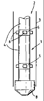
Figure 1 shows a schematic diagram of a casing assembly incorporating friction
reduction means;
Figure 2 shows a cross-sectional view through a section of the casing assembly
shown
in figure 1; and
Figure 3 shows a cross-sectional view of an outlet of the casing assembly
shown in
figures 1 and 2.
Referring to figures 1 and 2 a casing assembly I is shown within a well 2
having a
wall 3. The casing assembly I consists of casing sections 4}oined together by
sub-
sections 5. A plurality of outlets 6 are provided about the periphery of sub-
sections 5
which expel lubricating fluid supplied'under pressure via the interior of
sections 4 and
5. A float shoe 8 is shown connected to the bottom of the casing assembly 1.

CA 02360192 2001-07-10
WO 00/41487 PCT/GBOO/00029
3
Referring now to figure 3 an outlet 6 is shown in greater detail. The outlet
has a
threaded end 9 which screws into a corresponding threaded bore within a
respective
sub-section 5. Plate 10 has an aperture 11 therein to control the fluid
supplied to an
outlet 6. The apertures 11 may be differently sized at different depths to
achieve the
desired fluid distribution along the length of the casing assembly.
Fluid from the interior of sub-section 5 may flow through aperture 11 through
passage
12 and out via orifice 13. A flexible seal 14 may be provided about orifice 13
to assist
in assuring hydrodynamic lubrication between the orifice and the well wall 3.
Non-return valve 15 ensures that fluid can only flow in a direction from
aperture 11 to
orifice 13 and not in the return direction. Non-return valve 16 is retained in
a normally
open position by a fusible link 17. Fusible link 17 may be broken by an acid
or alkaline
pill to cause the valve to close and prevent fluid flow in the direction from
aperture 11
to orifice 13.
In use, float shoe 8 is initially closed and the casing assembly 1 is run down
well bore 4.
During this operation lubricating fluid is supplied to the interior of casing
section 4 and
sub-section 5 under pressure. Lubricating fluid from sub-sections 5 flows out
through
outlet 6 to create hydrodynamic lubrication between the casing assembly and
the wall 3
of well 2. This greatly reduces friction between the casing assembly 1 and the
wall 3 of
. well 2 both during start-up and as the casing assembly 1 is run into
position. This
reduces the load on connections between sections of casing as well as the
power of the
rig required to run the casing.
Once the casing has been run to a desired position an acid or alkaline pill is
introduced
into the lubricating fluid to be conveyed to the outlets 6. The alkaline or
acid
environment causes the links 7 to break, causing valves 16 to close due to the
action or
fluid pressure or under biasing from a biasing means.
The float shoe 8 is then opened. This is typically achieved by sending a steel
ball
through the inside of casing assembly I to impact and open float shoe 8. Thus
material
pumped down casing 1 may exit via the float shoe only and not via outlet 6.

WO 00/41487 CA 02360192 2001-07-10 PCT/GB00/00029
4
The casing assembly I is then cleaned and cement is then pumped down the
casing
under pressure which forces up to fill the spaces between casing assembly 1
and the
wall 3 of the well 2. The cement is followed by a drillable plug, formed of a
material
such as phenolic, aluminium or gun metal. The plug is forced to the bottom of
the
casing assembly to force the cement out of the casing assembly 1. The plug may
subsequently be drilled when the next stage of drilling is carried out.
To ensure that fluid is supplied to the locations most requiring lubrication
outlets 6 may
include gravity valves so that fluid is supplied when the casing assembly 1 is
substantially upright or the outlet is on the downward side of the casing
assembly I
(when running along a lateral) but not when the outlet is on the upper side of
the casing
assembly 1(when running along a lateral). This ensures that lubricating fluid
is
supplied only to those outlets resting against the wall of the well.
Although the invention has been described in relation to an embodiment in
which
sections of casing 4 are interconnected via subsections 5, it is to be
appreciated that
outlets could be provided directly from casing sections 4. The use of sub-
sections 5 is
preferred as this enables standard casing to be used without modification.
It will also be appreciated that the invention may be applied to liner, drill
pipe, or coil
tubing with obvious modifications.
Where in the foregoing description reference has been made to integers or
components
having known equivalents then such equivalents are herein incorporated as if
individually set forth.
Although this invention has been described by way of example it is to be
appreciated
that improvements and/or modifications may be made thereto without departing
from
the scope of the present invention.

Representative Drawing
A single figure which represents the drawing illustrating the invention.
Administrative Status

2024-08-01:As part of the Next Generation Patents (NGP) transition, the Canadian Patents Database (CPD) now contains a more detailed Event History, which replicates the Event Log of our new back-office solution.

Please note that "Inactive:" events refers to events no longer in use in our new back-office solution.

For a clearer understanding of the status of the application/patent presented on this page, the site Disclaimer , as well as the definitions for Patent , Event History , Maintenance Fee  and Payment History  should be consulted.

Event History

Description Date
Inactive: Expired (new Act pat) 2020-01-07
Common Representative Appointed 2019-10-30
Letter Sent 2015-01-08
Inactive: Payment - Insufficient fee 2011-12-29
Grant by Issuance 2008-06-10
Inactive: Cover page published 2008-06-09
Pre-grant 2008-03-20
Inactive: Final fee received 2008-03-20
Notice of Allowance is Issued 2007-12-10
Letter Sent 2007-12-10
Notice of Allowance is Issued 2007-12-10
Inactive: Approved for allowance (AFA) 2007-11-28
Inactive: Adhoc Request Documented 2007-10-23
Inactive: Delete abandonment 2007-10-23
Inactive: Abandoned - No reply to s.30(2) Rules requisition 2007-07-30
Amendment Received - Voluntary Amendment 2007-07-27
Inactive: S.30(2) Rules - Examiner requisition 2007-01-29
Amendment Received - Voluntary Amendment 2006-06-15
Inactive: IPC from MCD 2006-03-12
Inactive: S.30(2) Rules - Examiner requisition 2005-12-19
Amendment Received - Voluntary Amendment 2005-09-23
Inactive: S.30(2) Rules - Examiner requisition 2005-04-05
Letter Sent 2002-12-05
Request for Examination Received 2002-10-29
Request for Examination Requirements Determined Compliant 2002-10-29
All Requirements for Examination Determined Compliant 2002-10-29
Letter Sent 2002-07-03
Inactive: Single transfer 2002-05-10
Inactive: Office letter 2002-03-05
Inactive: Cover page published 2001-12-10
Inactive: Filing certificate correction 2001-12-03
Filing Requirements Determined Compliant 2001-12-03
Inactive: Courtesy letter - Evidence 2001-11-27
Inactive: Notice - National entry - No RFE 2001-11-19
Inactive: First IPC assigned 2001-11-19
Application Received - PCT 2001-11-08
Application Published (Open to Public Inspection) 2000-07-20

Abandonment History

There is no abandonment history.

Maintenance Fee

The last payment was received on 2007-12-17

Note : If the full payment has not been received on or before the date indicated, a further fee may be required which may be one of the following

  • the reinstatement fee;
  • the late payment fee; or
  • additional fee to reverse deemed expiry.

Please refer to the CIPO Patent Fees web page to see all current fee amounts.

Owners on Record

Note: Records showing the ownership history in alphabetical order.

Current Owners on Record
WEATHERFORD TECHNOLOGY HOLDINGS, LLC
Past Owners on Record
GEOFFREY NEIL MURRAY
Past Owners that do not appear in the "Owners on Record" listing will appear in other documentation within the application.
Documents

To view selected files, please enter reCAPTCHA code :


To view images, click a link in the Document Description column. To download the documents, select one or more checkboxes in the first column and then click the "Download Selected in PDF format (Zip Archive)" or the "Download Selected as Single PDF" button.

List of published and non-published patent-specific documents on the CPD .

If you have any difficulty accessing content, you can call the Client Service Centre at 1-866-997-1936 or send them an e-mail at CIPO Client Service Centre.


Document
Description 
Date
(yyyy-mm-dd) 
Number of pages   Size of Image (KB) 
Representative drawing 2001-11-21 1 4
Abstract 2001-07-10 1 39
Claims 2001-07-10 2 64
Drawings 2001-07-10 1 21
Description 2001-07-10 4 179
Cover Page 2001-12-10 1 28
Claims 2005-09-23 2 78
Description 2006-06-15 5 206
Claims 2006-06-15 3 93
Claims 2007-07-27 2 75
Representative drawing 2008-05-13 1 4
Cover Page 2008-05-13 1 29
Notice of National Entry 2001-11-19 1 195
Courtesy - Certificate of registration (related document(s)) 2002-07-03 1 134
Acknowledgement of Request for Examination 2002-12-05 1 174
Commissioner's Notice - Application Found Allowable 2007-12-10 1 163
Notice of Insufficient fee payment (English) 2011-12-29 1 93
PCT 2001-07-10 16 584
Correspondence 2001-11-19 1 13
Correspondence 2001-11-22 1 25
Correspondence 2001-12-03 1 27
Correspondence 2002-02-28 1 18
Correspondence 2008-03-20 1 30