Language selection

Search

Patent 2360254 Summary

Third-party information liability

Some of the information on this Web page has been provided by external sources. The Government of Canada is not responsible for the accuracy, reliability or currency of the information supplied by external sources. Users wishing to rely upon this information should consult directly with the source of the information. Content provided by external sources is not subject to official languages, privacy and accessibility requirements.

Claims and Abstract availability

Any discrepancies in the text and image of the Claims and Abstract are due to differing posting times. Text of the Claims and Abstract are posted:

  • At the time the application is open to public inspection;
  • At the time of issue of the patent (grant).
(12) Patent Application: (11) CA 2360254
(54) English Title: PRINTING AND DELIVERY DEVICE FOR LABEL TAGS
(54) French Title: DISPOSITIF D'IMPRESSION ET D'ACHEMINEMENT POUR DES ETIQUETTES A ATTACHER
Status: Deemed Abandoned and Beyond the Period of Reinstatement - Pending Response to Notice of Disregarded Communication
Bibliographic Data
(51) International Patent Classification (IPC):
  • B65C 7/00 (2006.01)
  • B65C 9/46 (2006.01)
(72) Inventors :
  • HASCHKE, EGGO (United States of America)
(73) Owners :
  • POLY-CLIP SYSTEM GMBH & CO. KG
(71) Applicants :
  • POLY-CLIP SYSTEM GMBH & CO. KG (Germany)
(74) Agent: ROBIC AGENCE PI S.E.C./ROBIC IP AGENCY LP
(74) Associate agent:
(45) Issued:
(86) PCT Filing Date: 2000-01-13
(87) Open to Public Inspection: 2000-07-20
Availability of licence: N/A
Dedicated to the Public: N/A
(25) Language of filing: English

Patent Cooperation Treaty (PCT): Yes
(86) PCT Filing Number: PCT/EP2000/000298
(87) International Publication Number: WO 2000041934
(85) National Entry: 2001-07-13

(30) Application Priority Data:
Application No. Country/Territory Date
199 01 039.0 (Germany) 1999-01-14

Abstracts

English Abstract


The invention relates to a device for printing and delivering semi-rigid tag-
type labels (5) to packaging and sealing machines. Said device comprises a
feed unit having a finger (13) which moves linearly to and fro and during the
working stroke grasps a shoulder of the label concerned and advances said
label along a defined trajectory. During the return stroke it glides over the
next label and grasps the shoulder of said label at the end of the return
stroke. This ensures that each tag-type label is correctly printed and
delivered for attachment to the object to be labeled. Preferably, one label at
a time from a chain of labels connected by perforations is cyclically moved
from a ready position into a peel-off position and the next label is printed
during the return stroke.


French Abstract

L'invention concerne un dispositif pour imprimer des étiquettes à attacher (5) et les acheminer à des sertisseuses-empaqueteuses. Dans ce dispositif, une unité d'avance présente un doigt (13) animé d'un mouvement de translation alternatif, qui, lorsqu'il effectue une course de travail, saisit par l'arrière une partie postérieure d'une étiquette respective et fait avancer cette dernière sur un trajet défini, tandis qu'il glisse sur l'étiquette suivante, lors de sa course de retour, jusqu'à ce qu'il saisisse par l'arrière la partie postérieure de l'étiquette suivante, à la fin de sa course de retour. Ce mode de fonctionnement assure l'impression correcte de chaque étiquette individuelle et l'acheminement de cette dernière pour qu'elle soit fixée sur l'objet à étiqueter. Selon l'invention, une étiquette, provenant d'une chaîne d'étiquettes suspendues les unes à côté des autres par l'intermédiaire de perforations, quitte à chaque fois une position de mise à disposition pour venir occuper une position de retrait, et l'étiquette suivante est imprimée pendant la course de retour.

Claims

Note: Claims are shown in the official language in which they were submitted.

7
CLAIMS
1. A device for printing and delivering semi-rigid label
tags (5) to packaging and sealing machines such as sausage
clip machines or the like, comprising a feed means for with-
drawing a strand of labes (5a) from a supply (7) and advanc-
ing the strand of labels along a guideway (4) to a delivery
station, the feed means having at least one finger (13)
translationally moved to and fro, which during the working
stroke cooperates with a shoulder (5b) of the respective la-
bel (5') so as to feed the same, whereas during the return
stroke it moves over the succeeding label (5"),
characterized in that a carriage (12) movable to and fro par-
allel to the guideway (4) carries the finger (13) on the one
hand and on the other hand a printing or embossing roller
(15) of a printing station, which roller is lifted off during
the working stroke and during the return stroke is urged
against the succeeding label (5) for inscribing the same.
2. The device as claimed in claim 1,
characterized in that the finger has the shape of a two-prong
fork (13), which grasps behind two shoulders (5b) of the re-
spective label aligned vertical to the feed direction.
3. The device as claimed in claim 1 or 2,
characterized in that during the return stroke a pin (23) ex-
tending vertical to the label feed plane biases the succeed-
ing label into the plane of action of the finger or fork
(13).
4. The device as claimed in claim 1,
characterized in that the painting or embossing roller (15)
urges the label (5) against a stationary printing matrix (18)
provided with adjustable sets of characters.

8
5. The device as claimed in any of the preceding claims,
characterized in that a deflection portion (22) at the outlet
end of the guideway (4) deflects the front portion (5d) of
the label (5).

Description

Note: Descriptions are shown in the official language in which they were submitted.


' CA 02360254 2001-07-13
1
PRINTING AND DELIVERY DEVICE FOR LABEL TAGS
This invention relates to a device for printing and deliver-
ing semi-rigid label tags to packaging and sealing machines
such as sausage clip machines or the like, comprising a feed
means for withdrawing a strand of labels from a supply and
moving the strand of labels along a guideway up to a delivery
station, the feed means having at least one finger transla-
tionally moved to and fro, which during the working stroke
cooperates with a shoulder of the respective label so as to
feed the same, whereas during the return stroke it moves over
the succeeding label. Such labelling machine for identifying
bunched produce or the like is known from US-A-4,519,178.
It is furthermore known to print self-adhesive labels in con-
nection with automatic label tapes, which are associated to
machines for packaging foodstuffs, directly before delivering
the labels, in order to attach for instance information as to
the expiration of the packaged foodstuff only at the packag-
ing time relevant for the expiration date. For certain food-
stuff packages self-adhesive labels are not suited because
they do not adhere sufficiently for instance to moist or
greasy sausage casings. For these cases it is known to incor-
porate label tags instead of a self-adhesive label in the
means used for sealing for instance sausage ends, i.e. to in
particular fix a portion of the tag together with a neck of
packaging material at the package by means of a closure clip.
What is problematic in the one as in the other case is the
reliable printing of the label tags shortly before processing
the same and thus in the course of the delivery of the labels
to the sealing machine. From DE 24 17 225 A1 a labelling de-
vice for successive tubular packages (such as sausages) is
known, wherein two labels connected by a connecting thread
are each cut off from a label strip and are delivered to a
means for sealing adjacent packages such that the connecting

' CA 02360254 2001-07-13
2
thread is seized by the clips sealing on the one hand the end
of the leading package and on the other hand the beginning of
the succeeding package, and thereupon both the labels and the
connecting thread are cut through. The feed is effected by
means of a pivotally mounted double-finger arrangement, which
during the feed movement grasps behind cuts in the strand of
labels and during the return stroke glides over the succeed-
ing labels. However, the labels a.re completely printed and
cannot be provided with actual information such as expiration
dates or the like at the moment of processing.
This problem should be eliminated by means of the invention.
In a delivery device for label tags as stated above it pro-
vides on. the one hand that a carriage movable to and fro par-
allel to the guideway on the one hand carries the finger and
on the other hand carries a printing or embossing roller of a
printing station, which roller is lifted off during the work-
ing stroke and during the return stroke is urged against the
succeeding label for inscribing the same. This ensures that
each label is exactly printed directly before being delivered
to the packaging machine and that it gets into the delivery
station.
Preferably, the finger has the shape of a two-prong fork
which grasps behind two shoulders of the respective label
aligned vertical to the feed direction. This stabilizes the
translational feed and prevents any canting and thus jamming
tendency. In accordance with one embodiment it is provided
that during the return stroke a pin extending vertical to the
label feed plane biases the succeeding label into the plane
of action of the finger or fork. It is basically irrelevant
3o whether for the working stroke the label is raised into the
plane of action of the finger or fork or said finger or fork
is lowered into the plane of the label. Because of the resil-

CA 02360254 2001-07-13
3
fence of the label material it is, however, also possible to
leave it at one plane and during the return stroke have the
prongs of the fork elastically bend the label on both sides,
so that at the end of the return stroke the label completely
returns to the plane of the fork. The pin stationarily
mounted in the center between the paths of the fork prongs
each time urges against the front area of the succeeding la-
bel such that it reliably lifts the adjacent shoulders of the
label to be fed into the delivery station into the plane of
action of the fork prongs and holds them there.
Inscribing is advantageously performed such that the printing
and embossing roller urges the Label against a stationary
printing matrix provided with adjustable sets of characters.
Thus, the one stroke of the feeding means is used for advanc-
ing the strand of labels and the other stroke (return stroke)

CA 02360254 2001-07-13
- 4 -
is used for printing the succeeding label. Thus, upon termi-
nation of one batch only individual labels get lost at best
because of a future wrong printing.
The invention is illustrated in the drawings, wherein:
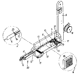
Fig. 1 shows a schematic general drawing of the device in
a top view partly tilted into the drawing plane;
Fig. 2 shows a perspective representation of the device
without feed roller;
Fig. 3 shows a perspective view similar to Fig. 2, where
parts of the device have been omitted or cut away;
Fig. 4 shows the feeding fork in a perspective representa-
tion; and
Fig. 5 shows the relative position of the feeding fork and
the labels in three difference cycle stages (A-C)
in a top view and in a side view.
At a bottom angle 1 a vertical table 3 is fixed by means of
posts 2, in which table the guideway 4 for a strand of labels
is incorporated. To the (rear of the) table 3 a further
post 6 is attached, which carries the supply 7 of labels 5 in
the form of a roller rotatably mounted on the carrier. The
label strand 5a runs from the supply 7 via a deflection
roller 8 into the guideway 4 of the table 3.
On rods 10, which extend parallel to each other and to the
table 3 between holders 11, a carriage 12 is mounted so as to
be translationally movable between the holders 11. A pneu-
matic piston/cylinder unit not represented in detail cycli-
cally moves the carriage 12 to and fro between the holders
11.

CA 02360254 2001-07-13
_ 5 -
To the carriage 12, there is on the one hand attached a fork
13 effecting the feed of labels, the cranked prongs 14 of
which fork protruding into the guideway 4 in the table 3
(Fig. 4). On the other hand, a contact roller 15 (printing or
embossing roller) is mounted on the carriage 12, namely such
that by means of a piston rod 16 and another pneumatic pis-
ton/cylinder unit 17 it can be urged against the labels pre-
sent in the feed path 4 or can be lifted off the same (Fig.
1).
On about half the feed path of the carriage 12 between the
holders 11 to the rear of the table 4 a printing unit 18 with
adjustable sets of characters is provided, which through an
opening in the guideway 4, which opening is not represented,
but indicated in Fig. 3, prints the desired inscription onto
the label 5 present there in the ready position, when during
the return stroke of the carriage 12 (towards the supply 7)
the label is urged from the roller 15 against the printing
unit 18.
In feed direction subsequent to the table 3 a front part 20
is attached, which prolongs the guideway 4 and accommodates
labels 5 when they are advanced from the ready position in
the vicinity of the table 3. A tiltable cover 21 (Fig. 2;
omitted in Fig. 3) closes the guideway 4 inside the front
part 20. At the end of the guideway 4 it has a deflection
portion 22, which deflects the respectively foremost label 5
when the same is pushed out, so that it is seized by the
processing sealing machine and is torn off the succeeding la-
bel by tensile force.
Fig. 3 shows a label 5' in the foremost (delivery) position
and behind the same the succeeding label 5~~ in a transfer po-
sition. The fork 13 effecting the feed - just as the carriage
12 moving the fork - is disposed in the rearmost position.
Therefore, the cranked prongs 14 of the fork 13 grasp behind

CA 02360254 2001-07-13
- 6 -
shoulders 5b of that label 5, which shoulders are formed in
that the front portion 5d of the label adjoining the rear
edge 5c is narrower than its succeeding portion 5e (Fig. 5).
Between the rear edge 5c and the front portion 5d of the sub-
sequent label a predetermined breaking point is provided in
the form of a perforation which faciliates tearing off the
label 5 that has been transferred to the sealing machine.
Fig. 5 also illustrates the course of the feed of labels in
the guideway 4 of the table 3. In the representation as shown
in Fig. 5a a feeding stroke has just been terminated, where
the fork 13 with its prongs 14 had grasped behind the shoul-
ders 5b of the foremost (partly cut away) label 5~ and had
pushed from right to left - in the drawing. The second label
5~~ is in the transfer position, whereas the third label 5~~~
is in the ready position and during the following return
stroke is printed in the manner described above.
This (half) return stroke position is shown in Fig. 5b. The
fork 13 - only indicated in dash-dotted lines as in the re-
maining partial figures of this drawing - glides back over
the label 5~~, slightly bending it off on both sides (which is
not represented). However, a pin 23 rests against the bottom
surface of the front area of the front label portion 5d and
urges the same towards the fork such that it is ensured that
upon reaching the fully retracted position of the fork 13
represented in Fig. 5c the label 5~~ is also kept ready in the
feed path 4 such that during another feeding stroke of the
fork 13 (to the left in Fig. 5c) the prongs 14 of the fork 13
again safely grasp below or behind the shoulders 5b of the
label 5" and advance the same from the transfer position into
the delivery position.

Representative Drawing
A single figure which represents the drawing illustrating the invention.
Administrative Status

2024-08-01:As part of the Next Generation Patents (NGP) transition, the Canadian Patents Database (CPD) now contains a more detailed Event History, which replicates the Event Log of our new back-office solution.

Please note that "Inactive:" events refers to events no longer in use in our new back-office solution.

For a clearer understanding of the status of the application/patent presented on this page, the site Disclaimer , as well as the definitions for Patent , Event History , Maintenance Fee  and Payment History  should be consulted.

Event History

Description Date
Inactive: IPC from MCD 2006-03-12
Application Not Reinstated by Deadline 2004-01-13
Time Limit for Reversal Expired 2004-01-13
Deemed Abandoned - Failure to Respond to Maintenance Fee Notice 2003-01-13
Letter Sent 2002-08-15
Inactive: Single transfer 2002-06-25
Inactive: Cover page published 2001-12-10
Inactive: Courtesy letter - Evidence 2001-11-20
Inactive: Notice - National entry - No RFE 2001-11-19
Inactive: First IPC assigned 2001-11-19
Application Received - PCT 2001-11-08
Application Published (Open to Public Inspection) 2000-07-20

Abandonment History

Abandonment Date Reason Reinstatement Date
2003-01-13

Maintenance Fee

The last payment was received on 2002-01-10

Note : If the full payment has not been received on or before the date indicated, a further fee may be required which may be one of the following

  • the reinstatement fee;
  • the late payment fee; or
  • additional fee to reverse deemed expiry.

Please refer to the CIPO Patent Fees web page to see all current fee amounts.

Fee History

Fee Type Anniversary Year Due Date Paid Date
Basic national fee - standard 2001-07-13
MF (application, 2nd anniv.) - standard 02 2002-01-14 2002-01-10
Registration of a document 2002-06-25
Owners on Record

Note: Records showing the ownership history in alphabetical order.

Current Owners on Record
POLY-CLIP SYSTEM GMBH & CO. KG
Past Owners on Record
EGGO HASCHKE
Past Owners that do not appear in the "Owners on Record" listing will appear in other documentation within the application.
Documents

To view selected files, please enter reCAPTCHA code :


To view images, click a link in the Document Description column. To download the documents, select one or more checkboxes in the first column and then click the "Download Selected in PDF format (Zip Archive)" or the "Download Selected as Single PDF" button.

List of published and non-published patent-specific documents on the CPD .

If you have any difficulty accessing content, you can call the Client Service Centre at 1-866-997-1936 or send them an e-mail at CIPO Client Service Centre.


Document
Description 
Date
(yyyy-mm-dd) 
Number of pages   Size of Image (KB) 
Representative drawing 2001-11-22 1 11
Drawings 2001-07-13 3 75
Claims 2001-07-13 2 58
Abstract 2001-07-13 1 71
Description 2001-07-13 6 308
Cover Page 2001-12-10 1 44
Reminder of maintenance fee due 2001-11-19 1 112
Notice of National Entry 2001-11-19 1 195
Request for evidence or missing transfer 2002-07-16 1 109
Courtesy - Certificate of registration (related document(s)) 2002-08-15 1 112
Courtesy - Abandonment Letter (Maintenance Fee) 2003-02-10 1 176
PCT 2001-07-13 10 363
Correspondence 2001-11-19 1 23
Fees 2002-01-10 1 30