Note: Descriptions are shown in the official language in which they were submitted.
CA 02360398 2004-05-26
-1-
This application is a division of Canadian patent
application Serial No. 2,034,423 filed January 17, 1991.
The present invention relates to improved manganese
activated zinc silicate phosphors. More specifically, the
present invention involves coating a willemite phosphor
with a layer of silica and then a coating of alumina. The
"bi-layer" phosphor obtained shows improved lumen
characteristics and is particularly useful in fluorescent
lU l amp s .
During certain phosphor synthesis and lamp fabrication
steps, the finely divided luminescent materials may be
exposed to oxidizing (oxygen-rich) atmospheres at elevated
temperatures. An example of this is the so-called
' lehri.ng' process used to burn away organic aqueous lamp
coating dispersion. It is well known that the brightness
of the finished fluorescent lamp may be reduced
significantly as a result of the lehring operation (the
20 so-called 'lehrl:oss'). This reduction in brightness may
result from.a partial oxidation of reactive low valence
ions present in the phosphor lattice.
A somewhat more involved example relates to the
process in U.S. Patent 4,585,673 wherein the formation of
protective coatings (typically alumina coatings) upon the
surfaces of finely divided phosphor particles via chemical
vapor deposition using an organometallic precursor in a
gas-fluidized bed is disclosed. When manganese-doped zinc
silicate is alumina-coated via the process described in
30 the '673 patent, and when fluorescent lamps are fabricated
from the coated phosphor produced therefrom, tln.ese lamps
display much better lumen maintenance than do similar
lamps fabricated using the virgin (uncoated) zinc silicate
phosphor. During the fabrication of such lamps, the
phosphor particles are typically dispersed in an aqueous
medium. Unfortunately, if the water-based suspension is
CA 02360398 2001-10-29
-2-
held-over for several days before use (a typical
situation), the beneficial effects associated with the
'673 coating are lost.
This 'holdover' problem can be overcome, however, by
annealing the alumina-coated phosphor in the air at a
temperature between about 700°C and about 850°C for a
period of time ranging from about 15 minutes to about 20
hours as described in U.S. Patent 4,805,400.
Unfortunately, while this coated phosphor annealing
process solves the holdover problem, it also causes the
zinc silicate phosphor to react with the alumina coating.
Zinc and manganese diffuse into the alumina coating,
probably forming a mixture of zinc and manganese
aluminates. The coated phosphor develops a 'body color',
and suffers a reduction in visible light emission upon
exposure to an ultraviolet light source. Moreover, very
similar phenomena are observed, as well, when the virgin
(uncoated) phosphor is subjected to the annealing process.
The increased body color and reduced brightness which
result from annealing both the uncoated and the '673
coated zinc silicate phosphor are believed to partially
result from the oxidation of some of the divalent
manganese ions located on the surface of the uncoated
phosphor particles or within and on the surface of the
reactive alumina coating.
Prior to the present invention, there was no known
means of preventing these detrimental interactions between
the phosphor and the oxygen-rich atmosphere within the -
annealing furnace. By means of the method described
below, these detrimental interactions are virtually
eliminated, allowing a phosphor coated by the process
disclosed in the '673 patent to be thoroughly annealed
without suffering reflectance or brightness losses.
Another aspect of the present invention involves the
use of high brightness zinc silicate phosphors as
components of the triblend phosphors. As discussed
CA 02360398 2001-10-29
-3-
previously, coated zinc silicate phosphors are unstable in
the water based suspension systems used to manufacture
fluorescent lamps. The zinc silicate phosphors must be
annealed to stabilize the coated phosphor. However, the
performance of a zinc silicate phosphor suffers both in
terms of brightness output and lumen maintenance after
annealing. Attempts to improve the base phosphor
performance prior to annealing include remilling and
refiring (RMF) the phosphor. Such an alumina coated "RMF"
phosphor shows improved lumen characteristics when used as
a component in the high color rendition triblend layer.
However, the remilling and refiring process results in a
large loss of starting material, thus increasing cost of
the phosphor. The present invention solves these problems
in a novel and economical way.
In a related application, an improved compact fluores-
cent lamp can be manufactured using a coated willemite
phosphor as the green-emitting component. Compact
fluorescent lamps of the twin-tube and double twin-tube
variety have become important for energy conservation in
recent years since they have efficiencies which far exceed
those of conventional incandescent lamps. While these
lamps are very cost-effective with very short payback
periods, they, nevertheless, have high initial costs which
have limited the scope of applications in which they have
been exploited. Therefore, it is desirable to further
reduce the cost of these lamps through the use of less
expensive non-rare-earth-containing substitutes.
The compact fluorescent lamps currently employ two
rare-earth based phosphors. They are Y203:Eu (Sylvania
Type 2342) for the red emission and Ce,Tb Mg Aluminate:
Ce, Tb (Sylvania Type 2293) for the green emission. No
blue-emitting phosphor is required, since the blue
components of the mercury discharge are used to achieve
the proper color temperature of the emitted 'white' light.
More recently, LaP04:Ce,Tb, manufactured by Nichia
CA 02360398 2001-10-29
- 4 -
Corporation, is being considered as a replacement for the Type
2293. Because these materials contain expensive rare-earths as
the activators, they are some of the most expensive phosphors
commercially used.
As mentioned previously, a green-emitting zinc
ortho-silicate phosphor activated with manganese, also known by
the mineral name willemite can be improved by the application of
a bi-layer coating prior to annealing. The bi-layer consists of
a thin coating of silica applied between the base phosphor and a
conformal alumina coating which is exposed to the mercury
discharge. The base phosphor is a zinc silicate phosphor doped
with manganese and tungsten. This phosphor can be manufactured
on production scale equipment using a single step firing
procedure which provide very high yields (typically 90%). These
high yield and efficiencies of scale provide substantial
phosphor cost savings which far outweigh the cost of applying
the intermediate silica layer.
Finally the use of the willemite phosphor which has been
coated with silica and then with alumina can be used as the
green-emitting component of high color rendition fluorescent
lamp.
According to one aspect of the invention there is
provided a method for forming a continuous bi-layer coating in
phosphor particles in a phosphor powder comprising:
a) vaporizing a silicon-containing precursor material
into an inert carrier gas to form a carrier gas containing
vaporized silicon-containing precursor;
b) passing said carrier gas containing silicon=containing
precursor through a mixture of phosphor powder and up to 1
percent fluidizing aid to form a fluidized bed in which the
particles are suspended in the carrier gas and to envelop the
fluidized particles with vapor of silicon-containing precursor
material, said fluidized bed being maintained at a nearly
isothermal condition and a temperature above the decomposition
temperature of the silicon-containing precursor material;
c) agitating particles with agitating means in the
fluidized bed while said particles are suspended in the
CA 02360398 2001-10-29
- 5 -
fluidized bed and the carrier gas;
d) passing oxidizing gas into said fluidized bed
separately from said carrier gas containing vaporized
silicon-containing precursor and reacting said oxidizing gas
with the vaporized silicon-containing precursor on the particles
of the phosphor powder to form a continuous coating of silica of
predetermined thickness on the phosphor particles;
e) vaporizing an aluminum-containing precursor material
into an inert carrier gas to form a carrier gas containing
vaporized aluminum-containing precursor material;
f) passing said carrier gas containing vaporized aluminum
precursor material through the phosphor powder having a
continuous coating of silica as produced by step (d) to form a
fluidized bed in which particles are suspended in the carrier
gas containing vaporized aluminum precursor material and to
envelop the fluidized particles with vapor of
aluminum-containing precursor material; and
g) passing oxidizing gas into said fluidized bed of
step(f) separately from said carrier gas containing vaporized
aluminum-containing precursor material and reacting said
oxidizing gas with the vaporized aluminum-containing precursor
material on the particles of the phosphor powder having a
continuous coating of silica to form a continuous coating of
alumina of predetermined thickness on the phosphor particles
having a continuous coating of silica.
Some embodiments of the invention will now be described,
by way of example, with reference to the accompanying drawings
in which: -
FIGURE 1 is a schematic representation of an apparatus
suitable for coating phosphor particles.
FIGURE 2 is a bed temperature versus time graph for a
TMOS/02 coating run using a manganese activated zinc silicate
phosphor.
FIGURE 3 shows the weight percent of silica on phosphor
powder as a function of coating time.
CA 02360398 2004-05-26
-6-
FIGURE 4 shows the relative plaque brightness versus
weight percent of silica coating on a zinc silicate
phosphor.
FIGURE 5 shows a cross-sectional view of a phosphor
particle coated with a layer of silica which is coated
with a layer of alumina.
FIGURE 6 shows an elevational view of double coated
fluorescent lamp.
FIGURE 7 shows a cross-sectional view of the Lamp of
gig. 6.
FIGURE 8 shows the color points taken at 3 positions
of a double coated lamp using Type 2293 phosp3zor.
FIGURE 9 shows the color points taken at 3 positions
of double coated lamp using an "RMF" phosphor.
FIGURE 10 shows the color points taken at positions of
a double coated lamp using the phosphor of the present
invention.
One aspect of the present invention involves the
formation of a continuous and conformal coating of silica
on the surfaces of zinc silicate or cool white phosphor
particles via chemical vapor deposition (CVD) while the
phosphor particles are suspended within an isothermal gas
fluidized bed. In a second aspect of the present
invention silica coatings are used to prevent reductions
in brightness and the development of body color when
manganese activated zinc silicate (Zn 2Si04:Mn) phosphors
are heated in air at temperatures above about 600°C.
These silica coatings also act as diffusion barriers, pre-
venting the migration of zinc and manganese from the
surface of the Zn2Si04:Mn phosphor through the silica
coating and therefore also through continuous and
conformal alumina coatings that may be formed .on the
surfaces of the silica coated phosphor particl.es:'
A schematic representation of the fluidized bed
reactor used to coat the phosphor particles 16 with silica is
CA 02360398 2001-10-29
-7-
shown in Fig. 1. In Fig. 1, a feeder line 11 carries the
inert bubbler gas through valve 54 into a stainless
bubbler 12 which contains a silicon containing precursor
such as tetramethoxysilane (TMOS) or tetraethoxyortho-
silane (TEOS). In the bubbler 12, the coating precursor,
TMOS or TEOS is vaporized into the bubbler gas. The
bubbler is heated by heating means such as heating tape
(not shown). The bubbler gas containing the TMOS or TEOS
can be diluted by carrier gas to provide appropriate
concentration of reactants. The bubbler gas containing
the vaporized TMOS or TEOS is carried through connector
line 13 and is diluted by the carrier gas at valve 55
which is carried through line 111. Lines 13 and 111 join
and the resulting line is heated by heating tape 30 or
other means. The bubbler and carrier gas with the TMOS
passes through a stainless steel plenum 40 which is
maintained at a temperature of about 32°C. The carrier
gas along with the vaporized TMOS or TEOS then flows
through a porous stainless steel gas distributor 14. The
gas then flows into a quartz glass reaction tube 15.
Within the reaction tube 15 is a vibrating mixer 17.
Circumferentially located on the shaft of the vibrating
mixer 17 and near the vibrating disc 19 are a series of
holes 18 through which the oxidizing gas with or without
an inert diluting gas enters the reaction tube 15. Oxygen
is introduced to the reaction tube through line 21. No
diluting gas means for the oxygen is shown in Fig. 1. The
quartz glass reaction tube is surrounded by a furnace 20.~
EXAMPLE 1
Aluminum Oxide C (0.1%) was blended with each phosphor
as a fluidization aid. The temperature of the fluidized
bed reactor was maintained between 450°C and 460°C during
the coating process. Further, due to the moisture
produced within the high temperature fluidized bed as a
CA 02360398 2001-10-29
-8-
byproduct of the TMOS oxidation reaction, the fluidized
bed remained almost perfectly isothermal from the
beginning to the end of each coating process run. A
typical bed temperature versus time curve for a TMOS/02
coating run is shown in Figure 2. In a typical run, 400
mg of the phosphor are coated using a 32°C bubbler tem-
perature, with 0.5 1/min nitrogen gas (the fluidizing gas
medium) flowing through the TMOS bubbler, and with 0.6
1/min oxygen gas entering the fluidized powder bed
(through the hollow stirrer rod) at a point a few
centimeters above the level of the porous distributor
plate.
Coating reactions were carried out for times ranging
between 2.5 hours and 7.5 hours. Subsequently, the
amounts of silica deposited were determined analytically
for several of the coated phosphors. The results of these
determinations are listed in Table 1. These data are
plotted vs coating time in Figure 3. As shown, the amount
of silica deposited via the TMOS/02 coating reaction
increases linearly with increasing coating time.
CA 02360398 2001-10-29
-9-
TABLE 1
Results of Chemical Analyses for Silica
Coatings on TiKOS/02-Coated ZnZSi04
and Cool White Phosphors*
Coating Weight
Phosphor Time (hr1 Percent Si02
Zn Si0 5 1.65
Col W~ite 2~ 0.80
Cool White 5 1.77
Cool White 73~ 2.56
*400 gm phosphors 0.5 1/min bubbler flow rate; 32°C
bubbler temperature; 0.6 1/min 02 flow rate; inert carrier
gas for TMOS: N2.
The silica-coated and uncoated zinc silicate and cool
white phosphors were also examined via high resolution
scanning electron microscopy. Photographic images were
obtained at 20,OOOX and 50,OOOX magnification. There were
no features observed in the photomicrographs obtained with
the silica-coated.materials that were not observed in the
photomicrographs obtained with the corresponding uncoated
phosphors. Thus, the silica coatings produced via the
TMOS/02 reaction appear to be uniform and conformal to the
surfaces of the underlying phosphor particles.
The continuity of the silica coatings formed on the
ZnSi04:Mn and cool-white phosphors were examined using
X-ray photoelectron spectrometry. Typical normalized
relative atomic concentration data obtained with an
uncoated and a silica-coated ZnSi04:Mn phosphor are
compared in Table 2. Typical data obtained with an
uncoated and a silica-coated cool white phosphor are
similarly compared in Table 3. As shown in Table 2,
signals corresponding to zinc and manganese are completely
absent from the XPS spectra obtained with the
TMOS/02-coated zinc silicate phosphor. Similarly, except
for a very small calcium signal, the XPS spectra obtained
CA 02360398 2001-10-29
-lo-
with the TMOS/02-coated cool white phosphor contain no
evidence of the underlying phosphor. Thus, the silica
coatings formed upon the surfaces of the phosphor
particles appear to be continuous as well as conformal.
TABLE 2
Relative Atomic Concentrations of Surface
Elements from XpS Analyses of Uncoated and
Silica-Coated Zn2Si04:Mn
Coating Zn(3p) Sil2p) Mn(2p)
None 100 73 2
2 w/o Si0
(from TMOS/OZ 0 100 0
reaction)
TABLE 3
Relative Atomic Concentrations of Surface
Elements from XPS Analyses of Uncoated and
Silica-Coated Cool White Phosphor
Coating Ca(2p) F ls_ p(2sy
None 100 23 63
= 2 w/o Sio
(from TMOS/~2 <1 0 0
reaction)
EXAMPLE 2
Three different lots of Zn2Si04:Mn phosphor were
coated with silica according to the method described in
Example 1. Samples of each phosphor, before and after
silica-coating, were annealed in air for 4 hours at 750°C.
Additional samples were likewise annealed in the air for
one hour at 800°C. Portions of each annealed material
were pressed into so-called plaques (i.e., they were
pressed into molds so that uniformly flat horizontal
CA 02360398 2001-10-29
-11-
surfaces were ob~ained.) A spot brightness meter equipped
with a green photo-optic filter along with an unfiltered
mercury plasma ultraviolet light source was used to
measure a so-called plaque brightness for each sample, ex-
pressed relative to that of a sample of each uncoated and
unannealed phosphor. The results of these measurements
are listed in Table 4. The relative plaque brightnesses
measured with phosphor lot #1 are also plotted vs w/o
silica added during the TMOS/02-coating process in Figure
4.
30
CA 02360398 2001-10-29
-12-
TABLE 4
Relative Plaque Brightness of TMOS/02-Coated ZnZSi04:Ma*
w/o Si02 Anneal Relative Plaque
Phosphor Lot Coatinct Conditions Brightness (y)
1 0 none 100.0
4 hr/750°C 95.6
13~ hr/800°C 96.0
1 0.40 none 94,g
4 hr/750°C gg,3
13~ hr/800°C 100.4
1 0.80 none 86,g
4 hr/750°C gg,3
1~ hr/800°C 100.4
1 1.20 none 84.2
4 hr/750°C g9,3
13~ hr/800°C 100.4
2 0 none 100.0
4 hr/750°C g5,g
1~ hr/800°C 95.9
2 1.20 none 78,1
1~ hr/800°C 100.3
3 0 none 100.0
4 hr/750°C 95.7
1~ hr/800°C 95.9
3 1.20 none 80.0
13~ hr/800°C 101.9
*Bubbler Temp. - 32-33°C; Bubbler Flow Rate = 0.5 1/min;
O Flow Rate = 0.6 1/min; Powder Weight = 400 gm;
Gating Temp = 450-460°C.
As shown, the brightness of the uncoated phosphor is
lowered by at least 4% when annealed in the air at,750°C~
or at 800°C. A body color (corresponding to a reduction
in reflected visible light) also develops during the
annealing of the uncoated phosphor. On the other hand,
sizable reductions in brightness are also observed with
the unannealed silica-coated phosphors. Moreover, the
thicker the silica coating, the lower the measured plaque
brightness. For instance, the plaque brightness measured
CA 02360398 2001-10-29
-13-
with a zinc silicate phosphor coated with 1.20 w/o silica
(via the TMOS/02 reaction) is only around 80% of that
measured with the uncoated phosphor.
In contrast, plaque brightnesses nearly equal to or
exceeding those measured with the uncoated and unannealed
phosphor are obtained with silica-coated phosphors that
have been annealed in the air at temperatures between
750°C and 800°C. Such silica-coated and annealed
materials are also notable for an absence of the body-
color that develops during the annealing of the uncoated
phosphor. Therefore, whereas the uncoated phosphor cannot
be air-annealed without suffering a 4% - 5% reduction in
plaque brightness as well as a reduction in reflected
visible light, the brightness of a silica-coated phosphor
actually increases with increasing annealing temperature
to a level exceeding that measured with the uncoated and
unannealed phosphor, itself.
EXAMPLE 3
The implication of the data shown in Example 2 is that
detrimental interactions which normally occur between the
phosphor and the air during the annealing step are
prevented when the phosphor is coated with a thin layer of
silica. The body-color that develops during the annealing
of the uncoated Zn2Si04:Mn phosphor suggests that the Mn2+
ions located on or near to the phosphor particle surface
are oxidized during the anneal. However, it is possible
that the body color is due to oxidized tungsten at the
phosphor particle surface. The absence of this
undesirable body-color, the undiminished brightnesses
obtained with annealed silica-coated Zn2Si04:Mn phosphors,
and the observed continuity and conformality of the silica
coatings themselves indicate that the phosphor surface is
stabilized by the presence of the coating, thereby
preventing the surface manganese from interacting with the
oxidizing atmosphere within the annealing furnace.
CA 02360398 2001-10-29
-14-
That the phosphor surface is stabilized by the
presence of the silica coating may also be shown by
examining the coated phosphor using x-ray photoelectron
spectrometry. Listed in Table 5 are the normalized
relative atomic concentrations of A1, Zn, Si, and Mn
obtained with several samples from the measured XPS signal
intensities corresponding to the A1(2p), Zn(3p), Si(2p),
and Mn(2p) electrons, respectively. Sample 1 is a
Zn2Si04:Mn phosphor coated with alumina using aluminum
isopropoxide (AIP) as the organometallic coating
precursor. The AIP is vaporized into an inert carrier gas
and passed through a mixture of the phosphor powder and up
to 1 percent of a fluidizing aid to form an isothermal
fluidized bed of vaporized AIP and phosphor particles at a
temperature of 300°C or greater. Oxygen is passed into
the fluidized bed and reacted with the vaporized AIP to
form alumina on the outer surfaces of the phosphor
particles. Sample 3 was obtained by coating the same
phosphor with silica as described in Example 1 (using TMOS
as the coating precursor). Samples 2 and 4 were obtained
by air-annealing samples 1 and 3, respectively, for 4
hours at 750°C.
CA 02360398 2001-10-29
-15-
TABLE 5
Relative Atomic Concentrations for IBS Analyses
AIP/O -Coated, TMOS/O2-Coated, and
TMOS~02 AIP/OZ-Coated ZnZSi04:Mn
Sample
No. Material A1(2p) Zn(3p) Si(2p) Mn(2p)
AIP/O -Coated a
1 Zn2Si04 100 0 0 0
Sample 1, annealed
2 4 hr 750°C 100 13 0 3
TMOS/O -Coated b
Zn2Si04 0 0 100 0
Sample 3, annealed
4 hr 750°C 0 0 100 0
Sample 4, AIP-O - a'b
5 Coated 2 100 0 0 0
Sample 5, annealed
4 hr 750°C 100 0 0 0
a - 2% A1203 Coating
b - 2% Siv2 Coating
As shown in Table 5, none of the cations present in
the Zn2Si04:Mn phosphor are detected in the XPS spectra
obtained with the alumina-coated phosphor. This indicates
that the AIP/02 coating is continuous and thick enough to
filter any Zn(3p), Si(2p), or Mn(2p) electrons that might
be emitted under x-ray bombardment. In contrast,
relatively large Zn(3p) and Mn(2p) signals are detected
after annealing the alumina-coated phosphor for 4 hours at
750°C (sample 2). These results are interpreted to
indicate that these cations are mobile enough to migrate
through the alumina coating during the anneal. In sharp
contrast are the XPS data obtained with the TMOS/02-coated
samples. In this case, silicon is the only cationic
species detected either before or after the 4 hour 750°C
anneal, indicating that the zinc and manganese ions
present on the surface of the Zn2Si04:Mn phosphor do not
migrate through the silica coating during the anneal. The
CA 02360398 2001-10-29
-16-
fact that the alumina-coated phosphor possesses a distinct
body-color after the anneal (thought to be due to oxidized
manganese), whereas the annealed silica-coated phosphor
does not possess such a body-color can be understood from
these data.
Finally, consider the results obtained using the
Zn2Si04:Mn phosphor that has been silica-coated via the
TMOS/02 reaction and subsequently air-annealed for 4 hours
at 750°C (sample 4). A quantity of this silica-coated and
annealed phosphor was coated with alumina via the AIP/02
reaction as described previously. As shown in Table 5
(sample 5), A1 is the only cationic species detected via
XPS analysis of this material, indicating that the alumina
coating is continuous and uniformly thick enough to
prevent the detection of any Si(2p) electrons that might
be generated under x-ray bombardment. Most significant is
the fact that an identical result is obtained after
annealing the double-coated phosphor for 4 hours at 750°C.
In contrast to the results obtained with sample 2 (in the
absence of the silica diffusion barrier), the absence of
XPS signals indicating the presence of Zn, Si, or Mn near
to the surface of the annealed double-coated material and
the complete absence of any detectable body-color
indicates that the silica coating prevents the interaction
between the phosphor and the alumina coating that would
otherwise occur.
This conclusion is reinforced by the relative plaque
brightness data listed in Table 6. Shown are the measured
brightnesses (relative to that of the uncoated and
unannealed phosphor) of AIP/02-coated Zn2Si04:Mn before
and after a 4 hour 750°C anneal, both with and without a
TMOS/02 (silica) diffusion barrier. As indicated in the
table, the reduction in brightness observed with the
unannealed phosphor in the absence of the diffusion
barrier is more than twice that obtained with the
double-coated phosphor. More significantly, the reduction
CA 02360398 2001-10-29
-17-
in brightness observed with the annealed alumina-coated
phosphor in the absence of the diffusion barrier is an
order of magnitude greater than that obtained when the
alumina coating was applied over the diffusion barrier.
Thus, the plaque brightness measured with the
double-coated and annealed phosphor was only about 1%
below that measured with the virgin phosphor.
TABLE 6
Relative Plaque Brightnesses of AIP/O -Coated
Zn2Si04:Mn with and without un~erl~ing
Si02 Diffusion Barrier
w/o Si02 2 Anneal Plaque Brightness Relative 3
Coatina Conditions to that of Uncoated Phosphor
0 none 94.2%
4 hr/750°C 87.7%
1.20 none g7.3~
4 hr/750°C gg.g%
1 Ca. 2 w/o A1203 Coating
2 Si0 -coated phosphor was annealed 4 hours at 750°C
prig to coating with alumina
3 Plaque brightnesses relative to that measured with the
uncoated phosphor.
Due to the results obtained from Examples 1-3 it was
thought that the results of improved plaque brightness and
lumen maintenance could be extended to fluorescent lamps.
However, it is known that correlation between handlamp
plaque brightness and fluorescent lamp performance for a
given phosphor frequently do not exist. This results from
a multitude of factors including changes in the phosphor
CA 02360398 2001-10-29
-18-
which occur during lamp baking, lamp fabrication and the
contact of the phosphor with the mercury discharge.
Moreover, the mercury discharge within a fluorescent lamp
contains about 15% of its emission at 185 nm. This
short-wavelength emission can lead to enhanced brightness
and/or damage to the phosphor which can influence the
observed initial brightness and maintenance.
More specifically, in the case of the alumina coated
and annealed willemite phosphor, the fluorescent lamps
which have the highest lumen performance possess a plaque
brightness of 92% of the virgin phosphor. However, the
corresponding fluorescent lamp performance may only be a
few percent lower. Further, while the handlamp
photoluminescent performance is improved with a silica
coated and annealed phosphor, this material exhibits a
significant loss in brightness and catastrophic
maintenance loss within a fluorescent lamp. This behavior
is probably associated with the reaction of the phosphor
with the mercury discharge within the fluorescent lamp.
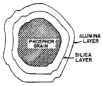
Shown in Fig. 5 is a cross-sectional view of a
phosphor particle coated with a bi-layer. The phosphor
grain is coated with a silica layer which prevents
diffusion from the phosphor grain to the surface coating
of alumina. It is also believed that the silica layer
prevents diffusion of the alumina layer to the phosphor
grain. Potential uses of the phosphor shown in Fig. 5 are
discussed below.
Historically silica and silica-containing phosphors-
used within fluorescent lamps are known to give rise to
appreciable maintenance loss, the uncoated willemite, in
fact, being a prime example of this. Therefore, any
improvement due to a protective layer over a silica
coating can be expected to be strongly dependent on the
quality and conformality of that layer as well as the
intrinsic resistance of the specific phosphor to
degradation in a fluorescent lamp.
CA 02360398 2001-10-29
-19-
EXAMPLE 4
Silica coatings were applied to the surfaces of zinc
silicate phosphors by CVD in a fluidized bed described in
Example 1. However, the tests were carried out using
typically 1500 gms. of phosphor in an 80 mm ID quartz tube
which employed a quartz frit as the distributor. Aluminum
Oxide C was blended with the phosphor at a concentration
of 0.1% by weight of the fluidized bed reactor was
maintained between 450 and 460°C during the coating
process. This temperature was monitored by a thermocouple
placed within the bed located at the midbed height. In a
typical run 2 liters per minute were run through a bubbler
containing tetramethoxyorthosilicate (TMOS) liquid
maintained at 32°C, and 3 liters per minute of undiluted
oxygen entered the bed through a hollow stirrer rod which
was located a few centimeters above the level of the
porous distributor plate. Coating reactions were carried
out between 1~ hrs. and 5 hrs. to effect the deposition of
predetermined amounts of silica coating. Table 7
summarizes the powder properties of the virgin phosphors
used in the following examples.
CA 02360398 2001-10-29
-20-
TABLE 7
Particle Properties of the Virgin Zinc Silicate
Phosphors Used in the Examples Cited
Surface FSS (fisher Coulter Counter
Area Sieve Size, Particle ~ize
Lot No. M2 1
(( /am) microns) sonic
3
66RMF 0.38 6.7 9.0 0.23
TK1-2M 0.44 6.1 7.72 0.26
TK2-U 0.52 5.1 6.65 0.27
1 Determined b sin le
y g -point BET measurements, using a
Quantachrome Monosorb surface area instrument.
2 Based on volume.
3 Q.D. is defined as (d o-d o)/(d o+d o
relative measure of75~re~~~h i~5~th~5/'particleg a
distribution.
Following coating, the phosphors were annealed in
28 quartz boats for about 4 hours at an annealing temperature
of approximately 760°C. At this point phosphors were
coated with alumina as described below.
The CVD coatings were carried out on the annealed
phosphors described above in a fluidized bed using
trimethyl aluminum (TMA) and oxygen as precursors. The
equipment and procedures for fluidized bed coating of
willemite phosphors are described in detail in U.S.~ Patent
No. 4,950,948. Briefly, a blend of approximately 1000 to
1300 gms. and 0.1% of Aluminum Oxide C by weight of
30 phosphor was loaded into a quartz fluidized bed column
comprising an 80 mm ID quartz tube having a quartz frit
fused to the bottom which acted as the distributor plate.
A 65 mm stainless steel agitator disc was attached to a
vibromixer agitator. Approximately 5 cm from the base, a
CA 02360398 2001-10-29
-21-
two-micron stainless steel filter element was welded in
line and functioned as a diffuser of the oxygen mixture.
The agitator disc itself was located approximately 25 mm
above the quartz distributor. A thermocouple, located at
the midbed height within the fluidized bed, was used to
monitor the temperature of the bed, which was maintained
between approximately 420 and 450°C.
The apparatus used for carrying out the coating reac
tions is shown in Fig. 1 with some slight alterations. In
a typical run, which lasted between 3 and 5 hours, 1750 cc
per minute of nitrogen passed through a bubbler 12
containing trimethyl aluminum (TMA) liquid which was main-
tained at 30°C. Another 1250 cc per minute of nitrogen
carrier gas was used to dilute the flow through line 111.
The combined flow was used to fluidize the phosphor
particles in reaction vessel 15. The oxygen as an
oxygen/inert gas mixture was introduced through line 21 at
2500 cc per minute of oxygen and 50 cc per minute of
nitrogen into the fluidized bed through the two-micron
filter element described earlier. Table 8 summarizes
specific coating parameters used for the examples cited.
CA 02360398 2001-10-29
-22-
h
m .
M U
O ~ ~
riN~ H
<
N
Z N ~ .~ w
N 'O
N N M O
N N
C U
~ O
N U 0~
M
N l0.
O
O '~ rJ lO
3 .~ IC
. . ri
N . ~
.
H
N
. '0
N ~
N W
i41
~
~
M ii ~0
M i'
M
Ifl y ~ M
O
V 0 U D 17 rl O ?n
~
ON u C
1
N ~
41 0.
' U V U U + m
O U
U
' ~
I O O ~ C .1
w O
O
M
N M
'r ~ "'~ * r~iA
~ ~
'r
~ 0 ~ ~ ~ b
~
~ o 0
mn n o I~ a m b
m t~
~ tn
~
D P P ~t f~ C ~ C
t~ .r
~
~
~ A
~
a ~! D r
~
O O O O C
O t~ N
O
O tI) ~ .
TJ N N ~ C OM
N O '~
~ .r
"~
"~
N
~' H < OM
p, 0.
10 1 N
a0
a0
~
Z ~ ~ ~ M .C p ~
p
O 0
O ON
i Ir C N
N N
~ ~C I I Z W m
1 b
4
1
~
1 j t tl1 W
M ~
I I 1 C C
M
M ~ I I I
C
C C
~ C
N I i 1 6 0 C A
P1 e V
B
1 1 I
~
1 ; i M
M M
M
la 1 i I C lO i i~
C C
C
i i i til o' a
e
1 s
~
i I ~ a tr
~
~
I I 1 N A w
N N
N
1 I 1 m
'C 1 1
~ ~
~
1 ' i w a
I
0 1 1 O
p
o
4 I t
1 ll li a
., t .'
ll
~
.~
..
~ C
,
A r W ~1 * ~ b
4
..iN .i h .i 0
J En
N ~ ~
M
= ~ 0 nOl
1 I I
I I I ~ C m
0 A O *
.~~'1
11 .OWn M W
n
. C < i
t1
.Hi C ~~1h
l3 O Am
CA 02360398 2004-05-26
-23-
Once the phosphor particles were coated, they were
transferred to quartz boats and annealed at approximately
760°C for 4 hours.
Lamp Testing
After the annealing step described above, the
phosphors were coated in 20WT12 or 30 WT12 fluorescent
lamps using conventional water base suspension systems.
The lamps thus coated were processed into finished
3.0 fluorescent lamps and photometrically evaluated. The data
were then converted to corresponding 40WT12 data using
established correction factors.
In the tests cited below, the bilayer coated and an-
neaied phosphors were tested against Sylvania Type 2293,
which is a Ce,Tb, Mg Aluminate phosphor used as a
green-emitting component in high color rendition lamps.
In addition, the uncoated virgin phosphor and the singly
coated and annealed (i.e., alumina only) phosphors were
also eva~.uated with the test.
20 Table 9 lists the lifetest results of the phosphors.
It is clearly evident that the bilayer coating provides
0-hr. brightness values which are either equivalent to or
exceeds that of the virgin phosphor lot. Also, both the
single- and bilayer-coated phosphors possess maintenance
which significantly exceeds the virgin phosphor. However;
the bilayer (A1203/Si02) annealed phosphor substantially
exceeds the brightness of the A1203-oily phosphor by 8%
for the 'RME' phosphor (66RME) to as much as 17% for the
singly fired willemite phosphors (TK1-2M and TK2-U lots).
30 Note that the brightness observed for the alumina-only
coated and annealed singly fired wil7~emite phosphor lots
are so low as to eliminate their consideration for
commercial use in conventional high color rendition lamps,
whereas the substantially higher brightness of the
A1203/Si02 coated singly fired phosphor allows its use in
* Trademark
CA 02360398 2001-10-29
-24-
triblend lamps. The thickness of the silica coatings are
derived from the information shown in Table 8.
TABLE 9
Lifetest Data for Various Willemite Phosphor
66RMF Lot
O hr 100 hr % M(0-100) 500 ~t(0-500)
hr
Virgin 5329 3800 71.3 --Discontinued--
#385 A1203 4860 4763 98.0 4685 96.4
#441 A1203/
Si0 5245 5101 97.3 5048 96.2
FFiXl6~
Type 2293 4923 4768 96.8 4685 95.2
TK1-2M Lot
O hr 100 hr % M(0-100) 500 ~I(0-500)
hr
Virgin 5199 --- --- --- ---
#578+ A1 O 4491 4424 98.5 --- ---
#479 A1
Si0 (~0~) 52I9 5193 99.5 4887 93.6
#476 ~rl203/ '
Si02 (I78A) 5239 5137 98.0 4894 93.4
FHX343
Type 2293 4873 4757 97.6 4499 92.3
+ This sample was run in a separate test against Type
2293 Lot FHX343. In that test fHX343 gave O hrs = 4903 1,
100 hrs = 4736 1, (0-100~I=96.6%). Therefore, the major
conclusions put forth are not affected.
TK2-U Lot
O hr 100 hr % M(0-100) 500 hr ~I(0-500)
Virgin 5021 --- --- --- ---
#425 A1203 4499 4332 96.3 4264 84.7
#443 A1203/
Si0 5084 4878 95.9 4842 95.2
FHX16~
Type 2293 4923 4768 96.8 4685 95.2 '
Note that values given have been corrected from
corresponding 20WT12 and 30WT12 to 40WT12 fluorescent lamp
data using established correction factors. Test Samples
for lots 66RMF and TK2-U were evaluated in 20WT12 lamps;
Lot TK1-2M was evaluated in 30WT12 lamps.
As mentioned earlier, the singly fired phosphor can
be manufactured on a production scale with much higher
yields than can be obtained using the 'RMF' synthesis.
CA 02360398 2001-10-29
-25-
The much higher yields and efficiencies of scale favor
substantial cost savings.
It is important to note that the addition of the
silica interface provides a major improvement in the
100-hr. brightness, as well, over the alumina coatings
alone. As the data in Table 9 show, Sample #479 has
yielded a 100-hour brightness of 5193 lumens. This
corresponds to the highest value ever achieved for a
willemite phosphor after 100 hours of burning corrected to
equivalent 40WT12 fluorescent lamp performance. This has
significant commercial implications since published
ratings of 'initial brightness' are actually those
determined after 100 hours of lamp operation.
When tricomponent blend suspensions are used which
consist of Y203:Eu for the red emission, Ba,Mg
Aluminate:Eu for the blue emission, and the 'RMF' coated
and annealed phosphor described by U.S. Patent No.
4,925,703 for the green emission, a color variation in the
emitted light is observed from the fluorescent lamp across
its length manifested by a slightly red coloration on the
more thinly coated end of the lamp and slightly green
coloration on the more thickly coated end of the
fluorescent lamp. This end-to-end color variation is
believed to be due, in part, to the disparity in particle
size between the red and green phosphors in the suspension
used to make the coated lamps. In fact, lamp fabrication
using Sample #443, a bilayer coated and annealed TK2-U lot
of smaller particle size than the 'RMF' phosphor, showed a
significant reduction in color nonuniformity compared to a
coated and annealed 66RMF phosphor (Sample #441) run in
the same test. Thus, the bilayer coating allows particle
size reduction. while maintaining excellent brightness for
high color rendition triblend applications
Table 10 lists the x-ray photoelectron spectroscopy
(XPS) analyses of the surfaces after each of the stages of
processing leading to the alumina only and alumina/silica
CA 02360398 2001-10-29
-26-
coated and annealed phosphors. The data clearly show that
the silica layer either eliminates or substantially
reduces the migration of Zn and Mn through the alumina
coating. It is also expected, although not experimentally
verified, that the silica interfacial layer also prevents
the migration of A1 ions from the alumina coating into the
zinc silicate phosphor. Both factors contribute to the
elimination of undesirable light-absorbing body color of
the annealed phosphor and the interference from impurities
that lead to the loss in generation of efficient
luminescence.
30
CA 02360398 2001-10-29
-27-
TABLE
10
X-ray Photoelectron Spectroscopy Analyses of
Coated Willemite Phosphors
Atomic
Percent
Sample Desiunation S1 Al O Zn Mn C
66 RMF
Virgin Powder 15.8 -- 54.6 22.3 0.7 6.6
CWM 120-89
(TMA coated) -- 43.4 51.6 <0.1 -- 4.9
#385 (TMA
coated/annealed) 42.0 52.5 4.3 0.2 1.1
TMOS 29L
(Silica coated) 38.5 -- 58.8 1.1 -- 1.4
#439 (Silica
coated/annealed) 39.0 -- 58.2 -- -- 2.g
CWM 330-89
(TMA coated #439) -- 44.1 51.6 -- 4.3
#441 (CWM 330-
89/annealed) -- 45.2 51.3 0.2 -- 3.2
TK-2U
Virgin phosphor 16.0 -- 48.6 17.7 0.9 16.0
CWM 313-89
(TMA coated) -- 43.7 52.8 -- --
3.5
#425 (TMA
coated/annealed) -- 36.9 45.8 10.1 0.4 6.6
TMOS 30L
(Silica coated) 36.4 -- 56.1 0.2 -- 7.3
#440 (Silica
coated/annealed) 37.2 -- 53.9 <0.1 -- 8.8
CWM 403-89
(TMA coated #440) -- 43.6 52.8 -- -- 3.6
#443 (CWM 403-89
annealed) -- 45.4 50.4 <0.1 -- 4.2
TK1-2M
Virgin phosphor 13.3 -- 44.1 27.7 0.5 14.3
TMOS 38L
(Silica coated) 38.1 -- 60.4 <0.1 -- 1.5
#477 (Silica
coated/anneal) 37.7 -- 59.8 <0.1 -- 2.4
CWM 614-89
(TMA coated #477) -- 42.5 53.1 -- -- 4.4
#479 (CWM 614-89
Annealed) -- 45.1 51.8 <0.1 -- 3.0
Lamp tests carried out employing the single-coated
alumina 'RMF' zinc silicate phosphor produced by the
Chemical and Metallurgical Division of GTE Products
Corporation, Towanda, PA, have shown a lower brightness
CA 02360398 2001-10-29
-28-
level in tri-phosphor blends when compared with the
rare-earth-containing blends run in the same test (See
Table lI). A bilayer (A1203/Si02) coated willemite
described employing a single-step fired willemite base
material in 40WT12 fluorescent lamps (Sample #541) has
yielded performance of 5280 lumens at 0 hours of lamp
operation and 5144 lumens at I00 hours with a maintenance
of 97.4% which exceeds that of the Type 2293 by almost 1%.
This performance substantially exceeds that obtained with
the best alumina-coated "RMF" materials heretofore
available. (See Table 11 for single- component life test
data) Thus, it is probable that this substantially less
expensive silica/alumina coated single-step fired
willemite phosphor is useful as single components and as
components of blends in double twin-tube lamps. This
phosphor will replace the more expensive Sylvania Type
2293 and the Nichia LaP04:Ce, Tb phosphors presently used.
Further uses for the silica/alumina coated phosphors are
discussed below.
30
CA 02360398 2001-10-29
-29-
TABLE 11
Lifetest data for ladescontainingalumina-coated
'Rtff'
~illemite and
rare-earth green
tri-phosphor
blends.*
Sins~le-Coat
Lamps: 20WT12,
3500K
Lumens
Green Test P.Wt. X Y 0 Hr 100 Hr -100
0
S~ ~ Hr
%M
Control
2293 1.95 0.410 0.398 1433 1389 96.9
6077
(Willemite) 1.85 0.408 0.397 1354 1308 96.6
Delta Lumens -79 -81
Delta Percent -5.5% -5.8%
Double-Coat Lamps: (Desis~ner,3500K)
20WT12, D35
Second Coat Lumens
Green Test P.Wt. X Y 0 Hr 100 Hr 0-100
Sample (gyms) Hr
%M
Control 2293 0.52 0.412 0.400 1353 1339 99.0
6077
(Willemite) 0.55 0.412 0.398 1314 1291 98.2
Delta Lumens -39 -48
Delta Percent -2.9% -3.6%
*Lifetest data for single components in 40WT12 fluorescent lamps are:
0 Hr 100 Hr (0-100 Hr)%M
Control 2293 4921 4740 96.3
6077 (60 RMF) 5019 4695 93.5
Virgin 60RMF(uncoated) 5134 4143 80.7
CA 02360398 2004-05-26
-30-
Referring to Figs. 6 and 7, there is shown in Fig. 6
an arc discharge lamp of the fluorescent type. The lamp
is comprised of an elongated glass tube l2,of circular
cross-section. It has the usual electrodes 64 and 66 at
each end supported by lead-in wires, 68, 70 and 22, 24,
respectively, which extend through glass presses 26, 28 in
mount stems 72, 32 to the contacts in bases 34, 36 affixed
to the ends of the lamp.
The sealed tube is filled with an inert gas such as
IO Argon or a mixture of Argon and Krypton at a low pressure,
for example 2 torr, and a small quantity of mercury, at
least enough to provide a low vapor pressure during
operation.
The interior of tube 12 is coated with a first layer
of phosphor 3$ such as, for example, a calcium
halophosphate activated by antimony and manganese.
A phosphor coating suspension was prepared by
dispersing the phosphor particles in a water=based system
employing polyethylene oxide and hydroxyethyl cellulose as
the binders with water as the solvent.
The phosphor suspension was applied in the usual
manner of causing the suspension to flow down the inner
surface of the bulb and allowing the water to evaporate
leaving the binder and phosphor particles adhered to the
bulb wall.
The first layer 38 was then dried prior to
overcoati:ng with a second phosphor layer 74 comprised of
narrow-band red- and blue- emitting phosphors and a
broad-band green-emitting phosphor. These two narrow-band
phosphors can be, for example, a yttrium oxide activated
by trivalent europium and having a peak emission at 611.
nm; and barium magnesium aluminate activated by divalent
europium and having a peak emission at 455 nm. The
broader band phosphor was aiumina/ silica-coated zinc
silicate activated by manganese and having a peak emission
at 528 nm.
CA 02360398 2001-10-29
-31-
The second phosphor layer containing the CVD-coated
phosphor is applied from a water-based suspension by
allowing the coating to flow down over the first phosphor
layer 38 until the phosphor coating drained from the
bottom of the bulb indicating the coverage of the phosphor
layer 38 was complete. Lamps made by this method usually
exhibit the thinnest coating thickness on the top end of
the bulb and the heaviest thickness on the bottom end,
where the suspension is allowed to drain. The
double-coated bulbs were then baked and processed into
fluorescent lamps by conventional techniques.
In the case where only a single layer lamp was made,
the methods were essentially the same as described herein
with the exception that the halophosphate layer was not
applied.
Control lamps were fabricated by identical
techniques as described above but had a narrow-band
green-emitting magnesium aluminate phosphor activated by
cerium and terbium in the second phosphor layer with a
peak emission at 545 nm. This phosphor is generally used
in the tri-phosphor blend but was replaced by the green
CVD-coated willemite phosphor in this invention.
Lamps employing a representative alumina-only coated
and annealed 'RMF' willemite phosphor, manufactured by the
Chemical and Metallurgical Division of PMG, Towanda, PA,
were also fabricated and incorporated into the testing.
Lifetest data and particle size information for the
single component willemite phosphors used for the
tri-phosphor blend lamps are given in Tables 12 and.l3,
respectively. These values have been corrected to obtain
the performance levels that would be observed with 40T12
fluorescent lamps using established correction factors.
CA 02360398 2001-10-29
-32-
TABLE 12
Lifetest data for single-component fluorescent lamps con
taining coated willemite phosphors (corrected to 40WT12)
0 Hr 100 Hr 500 Hr ~I(0-500 Hr)
Type 2293
(control) 4923 4768 4685 95.2
#425 (TK2-U)+ 4499 4332 4264 94.7
#443 (TK2-U)++ 5084 4878 4842 95.2
6103 (61RMF)+ 5085 4804 -4677 92.0
#441 (66RMF)++ 5245 5101 5048 96.2
+ Phosphor grains coated with only a single coating of
alumina, (sample 6103 was prepared at Chem. and Met.
Div.
PMG, Towanda, PA).
++ phosphor grains coated with both silica and alumina.
TABLE 13
Particle properties of the virgin zinc silicate
phosphors used in the examples cited.
FSS Coulter Counter
Lot Number (Fisher Sieve Particle Size (sonic)
Size, microns) 5~ QD.
Singly Fired
TK-U 5.1 6.7 0.27
~RMF~
60 RMF 7.4 9.3 0.21
61 RMF 8.0 10.0 0.21
66 RMF 6.7 9.0 0.23
For the evaluation of the tri-blends containing the
alumina/silica-coated willemite phosphor, two different
lamp types were used, and compared with controls which did
not have this phosphor in the blend. The lamps were
tested by photometering for light output in a standard
photometric sphere, both initially and at stated times.
In the following tables, light outputs are expressed in
CA 02360398 2004-05-26
-33-
lumens. Lamp color values were obtained by spectral power
distribution (SPD) measurements.
EXAMPLE 5
This example compares the light output and
maintenance of alumina/silica-coated and annealed
willemite phosphors in the tri-phosphor blends for double
layered 96-inch Designer 3000°K High Output Super Saver
fluorescent lamps. This lamp type has a tri-phosphor
weight in the second layer of about 15% of the total
phosphor in the two layers. The lamps were fabricated to
obtain the same x and y color coordinates for both the
test and control by adjusting the tri-phosphor blend
composition. The lamp test results are listed in Table
14. As the test data show, the lumens and lumen
maintenance of the test group are equivalent to the
rare-earth-containing Type 2293 control. This is in
contrast to previous results obtained with alumina-only
(single-coated and annealed) 'RME' phosphor where Designer
lamp brightness values were typically f% to 4% lower than
those obtained with the standard tri-phosphor blend (see
Table 11 for comparison).
* Trademark
CA 02360398 2001-10-29
-34-
0
O
u1
M
'
;~ J~~Wi'
~
O
O
O
O
U
O
_
H owl
~t
p ~ .
>C~ ~t W.
~
U O O
O
O
d
C
H .
I ~
H
. y r
p ~
O a
0
~
f3
N +s V
~ A4 .~-I .~ N
.ti .-i
ri
. ~ d
. ~
H
~
+~ E-~ ~ ~ -I N
3 x o
M b ~,~"~ O~ 01
CO 01
~
~
O
r1
M ~ G~1 ,~
M O
M
r-
i
H
a ~ o
~ W V
m 41 v
I Ul 1.+I-
O
~ '~ N
r~
~ ~
3'Q
~'
rl 01
a ~1 3 N
~ u1
H \ ~ ~ N UJ O N M
N ~
N
O
O ~ O ~ O O O
~ x O
~
'
~
N+~ O M o0 a0
d a0
as ~ d a m
1 3 o
~
o oa
~'
H
a, '~
r:
w ~ ao .~ o
o r.
W ,-~
~ r~
M
O u1
P.~ ~O '~
O vD
~ N v0 r-
~ ~O 1
~O
O ~ t~ O
H
~ O U
N
"U
,
.C I M ~ b V~JN n M
O d
~ 'S'O
~ ,.
,
HI f"I ~ Qi ~ 0
O
0 CO
rl o~ a0 00
w
~
m +I ~ a '~ o
.1
0
+~
~ n
~
A H U ,.d O
t +~
.C o 0 O
~e ~
3
W ~ ~ f~ ~ H
~ ~ ~
3
O . ,~ ~ M M ~r1
~ O ~
~ x ~'' o L, .o cn
.o
' o 0 ~ x r. ~
0 ~ r.
~ .~ m a o ao
v ~, o 00
~
~ v
b +~
~
N ~ V
N ~
H a ' a
f
/l
H ..~
4.1
N ~ N A
~
d 6 N ~ ~ V
O ~ N ~ ~ ,-i .-I
lI~ p M
U
~ ~ N~' ~ H~~
~
f~"+. O
VJ f1
v
v
~ H a o
~
~
H O U n
~t
~
a Ch U
i'~..
~.v...
CA 02360398 2001-10-29
-35-
EXAMPLE 6
As mentioned earlier, color nonuniformities of
fluorescent lamps containing the 'RMF' coated and annealed
phosphor occur and become more severe as the bulb length
increases. The 96-inch lamps have shown the most
pronounced variation. Color nonuniformities strongly
influence consumer acceptance of the lamp since they are a
premium-priced product designed for use in high color
rendition applications.
Figs. 8 through 10 show the color points taken from
the more heavily coated end (HE), middle (M), and more
lightly coated end (LE) of the fluorescent lamp containing
the rare earth green, the bilayer-coated 'RMF' phosphor
(#441), and the bilayer-coated single-fired willemite
phosphor (#443), respectively. Also shown are the two-
and three-step Macadam ellipses. The Macadam ellipse is a
way of assessing differences in visual color perception.
For acceptable lamps it is desirable to have all points
residing well within the two-step ellipse. As shown in
Fig. 8, the end-to-end color variation is excellent in the
case of the rare-earth green Type 2293. However, the
'RMF'-based phosphor shows a red and green variation along
the length of the lamp, as shown in Fig. 9. In contrast,
as shown in Fig. 10, the singly fired phosphor (Sample
#443) shows a significant improvement in color uniformity
over the 'RMF' phosphor, well within acceptable limits.
It is thought that the color non-uniformity originates
from a particle-size disparity between the red and green
phosphors that make up the dispersion from which the lamps
are made. Thus, the bilayer coatinct allows particle size
reduction of the crreen component while maintaininq
excellent bricthtness for hicth color rendition
applications. (As shown in Table 12, the fluorescent lamp
brightness obtained with the alumina/silica-coated small
particle phosphor (Sample #443) is much superior to that
CA 02360398 2001-10-29
-36-
obtained with the same base phosphor coated only with
alumina (Sample #425)).
EXAMPLE 7
This example compares the light output and
maintenance of alumina-coated and alumina/silica-coated
willemite phosphors in 40WT12 4100°K single-coat
tri-phosphor lamps. This test is designed to exaggerate
differences in performances between the green components
used in the triblends, since the single layer of high
color temperature requires the largest amount of green
compared to any other lamp that would be fabricated. That
is, any differences in performance will diminish as the
triblend layer thickness is reduced (in double layer
lamps) and as the lamp color temperature is reduced (since
the fraction of green component in the blend goes down as
the color temperature is reduced).
As the data in Table 15 show, the maintenance of all
materials tested are comparable. Further, the color
rendering index, measured after 100 hours of lamp
operation, is about 3 units higher for the
willemite-containing blends compared to the
rare-earth-containing blend, even in this single-coat
lamp, achieving CRI values in excess of 85.
CA 02360398 2001-10-29
-37-
~1 ~0M
O
O
h
m
?~
I
O O O O N V
C
C
N
O
~
XIM M M w 0~ O N
O
~
O
~
O O O O O ~ ~ P
~
P
0N.
'' C
s ~ o
~q' ~
~ a
rl
s
M ~ O n
4 M M ~y M f
i
1
N
.H
.~
m Y
d ~
~ ~
oo
.
N ~ ~0 N ~0 M 1~ ~ x .o
r
..
o
..
. ~ M
M
M
vt M M ~ C ~ O
O
O
M
~ 1 0.
N (
w
n
~ H C
~r~
<
H
* M S v0 '0 C O
~
" ' N O (~ Yl N
w O ~
~
~ M
M
N
w
1 to
m ~ 0
y o p ~ a
.. 0
a a w .
~ h
* O
w~
. o ~ a0 -y y i
1
0 0 4 ~ .~~ M
W ~ O ' C
. ~ ~ ~ M
O ~ N O ~"~ ~ a
~
N O t
~ r
0 C ~ W ~ C O
~ M
0 _ ~ .r M
C
O ~ H N N
W ~ .G 0 M M M
M M
M
O 4. r1 ~ 0 0
m
N 11 , 1
li < ~i p, a
~
E~ ~ ! ~
.~
a ,,.1
N H A
r 1
~
r o arx a a 'a o
p t w C
0 ~
a "_
1
Ew M M M 1! ~
0
NNN N .1 * Y
N N
.r .N
C C to M M
~t C 1 d ~
r
O ~ N
~ V
11 N O 11 '1 rl
N
N ~ ~
C
h
H C p '' M
C
~ O
is * ~
CA 02360398 2001-10-29
-38-
With regard to brightness, the bilayer-coated 'RMF'
phosphor (#441) is clearly superior to the representative
singly coated 'RMF' phosphor (G103). The brightness
performance of the bilayer-coated singly fired zinc
silicate (#443), while exceeding that of the
alumina-coated 'RMF' phosphor (G103), is about 2% below
that of the rare-earth Type 2293 control, at 1000 hours of
lamp operation. However, by way of comparison a singly
fired (smaller particle) willemite phosphor with only the
alumina coating (i.e., without the intervening layer of
silica) is completely unsuitable for use in triblend
applications because its brightness is about 10% below
that of the corresponding alumina/silica-coated phosphor
(i.e., less than 4500 lumens initial brightness in a
40WT12 fluorescent lamp), as shown in Table 12.
The use of the bilayer-coated phosphor provides a
substantial cost savings over the rare-earth blends in the
examples cited above since the tri-phosphor blend
represents the major cost of the lamp and, as Table 14
shows, the green component comprises over 30% of the
tri-phosphor blend.
Further, the use of the singly fired bilayer-coated
phosphor provides even further cost savings, since the
large-particle 'RMF' material with narrow particle size
distribution requires two firings in its synthesis with
multiple decantations to remove the "fines" fraction.
This necessarily results in low yields (typically 60%).
However, the smaller particle material can be made using a-
single-step firing followed by a washing which provides
much higher yields (typically 90%). Also, the smaller
particle material can easily be manufactured on
production-scale equipment. The much higher yields and
the efficiencies of scale all favor substantial cost
savings which far outweigh the cost of applying the
intermediate silica layer.
CA 02360398 2004-05-26
- 39 -
It is evident that fluorescent lamps will benefit greatly
from the use of the bilayer-coated and annealed singly fired
willemite phosphor by permitting a lower lamp price that finds
more acceptance in the marketplace.
Finally, while what has been described herein has been
fluorescent lamps employing CVD-coated phosphors in single-
and double-layered configurations, the scope of this
disclosure can include lamps which employ multiple layers of
phosphor coatings in the fabrication of the lamp, multiple
components of the blend in addition to, or otherwise different
from, the tri-phosphor blend formulation described herein so
long as they contain the bilayer-coated willemite as one of
the components, and the use of non-CVD-coated alumina/silica-:
coated and annealed willemite phosphor.
A method for forming a continuous layer of silica on
phosphor particles is disclosed. The method comprises
vaporizing a silicon containing precursor such as
tetramethyloxysilane (TMOS) or tetraethoxyorthosilane (TEOS)
into an inert carrier gas and passing this gas. containing TMOS
or TEOS through a phosphor powder wherein the phosphor
particles are enveloped in the TMOS or TEOS at a temperature
of greater than 400°C. An oxidizing gas is passed_into the
phosphor powder which reacts with the TMOS to form a
continuous coating of silica on the phosphor particles. The
resulting silica coated phosphor can then be further coated
with alumina.
While there has been shown and described what are at
present considered to be the preferred embodiments of. the
invention, it will be obvious to those skilled in the art that
various changes and modifications can be made without
departing from the scope of the invention as defined by the
appended claims.