Note: Descriptions are shown in the official language in which they were submitted.
CA 02360420 2001-07-13
WO 00/42394 PCT/ILOO/00027
1
DROPLET COUNTER FOR LOW FLOW RATES
Technical Field
The present invention relates to liquid metering. More particularly, the
invention provides a device capable of registering very low flows, being
particularly
useful in the laboratory and in medical applications, including intravenous
infusions,
blood flow control and urine output measurement.
Background Art
Flow meters for liquids have many important applications such as furnishing
information in medical applications, research, industrial and agricultural
work.
Known types of flow meter include the nutating-disk, lobed impeller, orifice
flow
obstruction, tapered tube rotameter, turbine, and magnetic types. The state of
the
art in flow meter development is represented by recent US Patents, among them
nos. 5,571,964 and 5,581,026 to Sawada et al., and no. 5,698,793 to
Carmichael.
Conventional types of flow meter become unreliable for low flows, and for very
low
flows which may be discontinuous no meaningful results are obtained. Yet there
is a
need for such measurements in applications such as for example for metering
the
urine output of some critical hospital patients.
In many hospitals it is common that the average urine flow is determined
hourly by having a nurse or attendant examine the transparent graduated
collection
bag located below the bed of the patient. In intensive care departments such
personnel are likely to be distracted by more urgent tasks and omit to take
such
measurements. The method is costly, unreliable and due to the flexible
collection
bag, also inaccurate.
Many special devices have been proposed. Among patent disclosures' are
devices for rainfall measurement and meters which are either intended for
urine
flow measurement or can be adapted for such purpose.
Dye et al. in US Patent no. 3,859,854 disclose an apparatus for measuring a
liquid discharge, which includes a receptacle including a wall, a cup shaped
pan,
and a chamber below the pan. Liquid is accumulated in a compartment, and the
height of the liquid is measured.
CA 02360420 2001-07-13
WO 00/42394 PCT/ILOO/00027
2
Wurster proposes a capacitance type of measurement for urine flow in US
Patent no. 4,051,431. Using the urine as an electrical conductor and as a
dielectric,
the capacitance is used to derive the volume of urine present.
Nehrbass in US. Patent no. 4,099,412 proposes to use a rotameter to
measure the instantaneous flow rate of urine discharge.
In US patent no. 4,484,582 Rottenberg et al. disclose a system for
measuring flow of electrolytic fluids, wherein a pair of electrodes are flush
with the
surface of a cylindrical flow cell. A monopolar pulse train is applied across
the
electrodes to effect a cell impedance inversely proportional to the flow rate.
Jespersen describes optical sensor means to operate a lower and an upper
valve described in US Patent no. 4,343,316. Intermittent discharge of a
measured
volume is used to indicate urine flow rate.
Parrish discloses an ultrasonic transceiver in a measuring system he
describes in US Patent no. 4,448,207. The transceiver is arranged to
periodically
measure the height level of a urine column.
LeVeen discloses a meter based on an optical sensor in US Patent no.
4,532,936. A peristaltic pump is used to empty the measurement column at a
known rate.
Carter et al. describes a pressure sensor in a funnel-shaped device
described in US Patent no. 4,554,687. A pressure transducer produces an
electrical
signal in response to air pressure resulting from urine accumulation. He
further
details a second variation using a sealed vertical air column in US Patent no.
4,683,748.
A device intended for flow measurement of small liquid volumes is disclosed
by Prestele in US Patent 4,559,831. He channels the liquid through a small
diameter tube into which gas bubbles are also fed. By measuring the advance of
the bubble, fluid flow rate can be deduced.
Westphal et al. suggest' a force transducer to weigh collected urine in an
apparatus described in US Patent no. 5,769,087.
Nelson proposes devices to measure rainfall by electronic drop counting in
US Patents 4,520,667 and 4,827,766. The latter patent discloses a vent tube
which
is partially liquid immersed.
CA 02360420 2010-05-07
3
Most flow measuring systems measure some related parameter to deduce
flow rate. However errors are introduced when the relationship between the
measured parameter and the flow rate is not constant. Such relationship is
often
effected by temperature changes, and by changes In the fluid density and
viscosity.
Few prior-art systems are capable of measuring extremely low flows, such as a
flow
of a few drops per hour.
In U.S. Patent 3,641,543 (D1), there is desc ribid a low-level detector and
drop rate
monitor, particularly for intravenous feeding apparatus. This patent primarily
relates
to the electronic means of detecting the drops and fluid to be monitored and
relates
only briefly to the mechanical apparatus which is of little importance to the
invention
described in said patent. While the drawing in figure 1 in said patent, shows
the
provision of an air line 11, in fact said patent does not teach or suggest the
device
of the present invention to a person skilled in the art since the device as
shown in
said figure, does not work. Specifically, since air One 11 extends into an
inverted
bottle which has no inlet, as the liquid flows therefrom a vacuum is created
in the
upper portion of container 12 which will balance against the force of gravity
and not
permit complete flow of the liquid from said bottle. Furthermore, valve
mechanism
20 is separate from the drop formation opening and if said valve is closed the
drops
will fall until they fill the second chamber whereby electrodes 38 and 40 will
be
unable to measure any drop formation. Finally, said patent does not teach or
suggest the arrangement of the present invention, wherein the flow restriction
element leads directly to the drop generator and instead in said patent, and
in other
patents discussed hereinafter, the flow restriction element 20 is in fact
positioned in
the line after the drop generator. Therefore, said patent neither teaches nor
suggests the present device.
I I
CA 02360420 2010-05-07
4
U.S. Patent 5,098,408 (D2), teaches the use of an automatic intravenous flow
controller wherein the primary purpose is to restrict the flow in a controlled
way. In
said patent, drops are formed along the outer surface of an icicle or stylus
drop
former positioned in fluid communication between an inlet and outlet end of
the flow
controller. These drops break away from the material of the icicle and the
surface
tension between the icicle and the fluid determines the size of the drops. The
drops
are not counted and the drops only serve as a rough visual indication of flow
rate.
In contradistinction, according to the present invention, the drops are formed
within
the drop generator and each droplet breaks away under its own weight from
liquid in
the drop generator orifice, i.e. by the breaking of liquid-liquid surface
tension.
U.S. Patent 4,520,667 (D3), teaches a non-mechanical digital rain gauge. As
can
be seen from the description in column 5 of said patent, the device is
designed in
such a manner that there will now be more than 2 rein drops entering the
opening
thereof in a second. Therefore, no flow restriction device is required or
taught and
each drop that enters the device passes into the drop generator and is
counted.
U.S. Patent 3,871,229 (D4), teaches a drop sensing apparatus with a flow
restriction device positioned along the tube feeding the needle. While flow
may be
corrected by said flow restriction device, as a result of the drop rate, this
patent
neither teaches nor suggests an arrangement wherein the flow restriction
element
leads directly to the drop generator.
In U.S. Patent 3,712,132 (D5), there is described a droplet monitoring probe
which
comprises 2 electric wires spaced a known distance apart from each other and
connected at one end to means for establishing a DC potential between the
wires.
A drop in the fluid stream momentarily contacts both wires causing an
electrical
signal, which may be counted. These droplets, however, are not falling
droplets
and instead, are droplets forming and flowing in a gas turbine.
CA 02360420 2010-05-07
4a
In U.S. Patent 4,261,388 (D6), there is described a drop rats controller for
controlling flow of fluid from an infusion fluid reservoir to an Intravenous
infusion sits
apparatus with a flow restriction device positioned along the tube feeding the
infusion site. While flow may be corrected by said flow restriction device, as
a result
of the drop rate, this patent neither teaches nor suggests an arrangement
wherein
the flow restriction element leads directly to the drop generator..
Thus it will be realized that none of said patents teaches or suggests a low-
flow
metering device as described and claimed herein, wherein the flow restriction
element leads directly to the drop generator and wherein there is provided
means
for measuring the time Interval between successive droplets and for
calculating flow
rates and total volume therefrom while dealing with variations in droplet size
as a
function of the tune interval between successive droplets.
It is therefore one of the objects of the present Invention to obviate the
disadvantages of prior art flow meters and to provide an apparatus which Is
able to
record flow of a few drops per hour.
It is a further object of the present invention to provide a flowmeter which
meets the requirements for registering urine output of catheterized patients,
and
also for metering Infusion rates.
Summary of the Invention
The present invention provides for a low-flow metering device for measuring
flows in the
range of from about 0.05 ml per hour to 6 litres per hour, the device
comprising: a) a first
chamber having a separate inlet, and a separate outlet in fluid communication
with a
second chamber said first chamber being provided with a drop generator having
a drop
generator orifice leading to said second chamber and sized to release a series
of
droplets, each of said droplets forming and breaking away under its own weight
from
liquid in the drop generator orifice fed thereto; b) electronic means
positioned in said
second chamber below said drop generator for counting the passage of each
droplet
CA 02360420 2010-05-07
4b
liquid in the drop generator orifice fed thereto; b) electronic means
positioned in said
second chamber below said drop generator for counting the passage of each
droplet
exiting therefrom; and c) an information processing unit connected to said
electronic
means for receiving and recording information and for measuring the time
interval
between successive droplets and for calculating flow rates and total volume
therefrom
while correcting for variations in droplet size as a function of the time
interval between
successive droplets, the inlet being for the introduction of an inflow of
liquid into and
through said first chamber, the first chamber being divided into an upper
reservoir
chamber and a lower drop generator chamber, said reservoir chamber and lower
drop
generator chamber being interconnected by an element creating a laminar flow,
wherein
an overflow conduit extends between an upper area of said first chamber and
said
second chamber for equalising gas pressure between said two chambers and
preventing
flooding of the first chamber in case of unexpectedly fast inlet flows.
In a further aspect of the present invention, there is provided a low-flow
metering device
for measuring flows in the range of from about 0.05 ml per hour to 6 litres
per hour, the
device comprising: a) a first chamber having a separate inlet and a separate
outlet in
fluid communication with a second chamber said first chamber being provided
with a
drop generator having a drop generator orifice leading to said second chamber
and sized
to release a series of droplets, each of said droplets forming and breaking
away under its
own weight from liquid in the drop generator orifice fed thereto, b) a counter
positioned
for counting the passage of each droplet exiting from said drop generator; and
c) an
information processing unit connected to said counter for receiving and
recording
information and for measuring the time interval between successive droplets
and for
calculating flow rates and total volume therefrom while correcting for
variations in droplet
size as a function of the time interval between successive droplets, the inlet
being for the
introduction of an inflow of liquid into and through said first chamber, the
first chamber
being divided into an upper reservoir chamber and a lower drop generator
chamber;
CA 02360420 2010-05-07
4c
wherein the counter is an optical sensor, and an overflow conduit extends
between an
upper area of said first chamber and said second chamber for equalising gas
pressure
between said two chambers and preventing flooding of the first chamber in case
of
unexpectedly fast inlet flows.
Brief Description of the Drawings
The invention wIA now be described in connection with certain preferred
embodiments with reference to the following Illustrative figures so that it
may
be more fully understood.
With specific reference now to the figures in detail, it Is stressed that
the particulars shown are by way of example and for purposes of illustrative
discussion of the preferred embodiments of the present invention only and are
presented in the cause of providing what is believed to be the most useful and
readily understood description of the principles and conceptual aspects of the
invention. In this regard, no attempt is made to show structural details of
the
invention in more detail than is necessary for a fundamental understanding of
the invention, the description taken with the drawings making apparent to
those skilled in the art how the several forms of the invention may be
embodied In practice.
In the drawings:
FIG. 1 is a diagrammatic view of a preferred embodiment of the metering
device according to the invention;
FIG, 2a is a diagrammatic view of an embodiment part of which is disposable;
FIG. 2b is a representation of the relationship between drop size and time
between
drops;
FIG. 3 is a diagrammatic view of part of an embodiment including a flow
regulator
and a labyrinth drop generator,
FIG. 4 is a diagrammatic view of part of an embodiment including a feed
reservoir;
FIG. 5 is a diagrammatic view of part of an embodiment including a collection
bag;
FI G. 6 is a block diagram of a system including a central monitor;
FIG. 7 is a sectional elevation of a further preferred embodiment;
and
FIG. 8 is a detail of the drop generator seen in FIG. 7.
CA 02360420 2010-05-07
Description of Preferred Embodiments
In a preferred embodiment of the present invention there is provided a
low-flow metering device wherein said electronic means comprise a pair of
electrodes positioned in spaced-apart relationship one above the other below
the
orifice of the drop generator.
In a most preferred embodiment of the present invention there is provided a
low-flow metering device wherein the element creating a laminar flow is a
molded
plastic labyrinth.
Yet further embodiments of the invention will be described hereinafter.
In U.S. Patent no.4,827,766 there is described and claimed a rain gauge
wherein the drop generator comprises of a very small diameter filter. Clearly,
such
filter will function only a short time before becoming blocked and thereby
completely
disabling the device.
In contradistinction thereto, the present invention in some embodiments
uses filter devices which are not size-restricted and in tither embodiments
flow is
restricted by a labyrinth. The technique of using a labyrinth for flow
restriction while
providing a flow path large enough to allow passage for small particles has
been
extensively proved in the field of agricultural drip irrigation tubing.
Furthermore, in contradistinction to US Patent 4,827,766, in the present
Invention the major portion of liquid in the upper chamber is directly
available
to the drop generator, allowing fast drop generation if necessary.
It will be realized that the novel device of the present invention is not
limited to the use of electrodes for drop detection. An optical sensor such as
a
light source directing a beam at a photocell can be used, being particularly
suitable where the liquid being measured Is colored, for example blood. In
case of transparent liquids, the light beam is deflected away from the
photocell. Alternatively, each drop can be detected and registered by a
capacitive proximity sensor. Recently much progress has been made in
reducing the physical size of optical and other sensors, making possible their
use In small instruments. Piezoelectric devices have also been improved and
cost-reduced in recent years, such device could be used to absorb the impact
of a falling droplet, the advantage being the high-frequency response of the
output charge.
CA 02360420 2010-05-07
6
It will be understood that the novel device of the present invention
serves to measure flow even when fluid supply is non-continuous. As even a
single droplet is registered by the electrodes or optical means, and there is
no.
practical limit to the time span between one droplet and the next, very low
flow
rates can be reliably metered. Applications include infusions, urine output,
rainfall measurement, patient's blood input or output, patient feeding with
liquids, and determining the results of overhead irrigation in agriculture.
The invention provides means for measuring the time interval between
successive droplets, and calculates flow rates therefrom. It is realized that
the
size of the droplets may change in relation to said time interval. Means for
dealing with variation in droplet size are provided as will be seen with
reference to FIG. 2a and 2b.
Furthermore, an embodiment of the invention, described with reference
to FIG. 7 is able to recognize very fast inflow causing overflow and to report
such condition', as well as being able to report a full collection bag, and to
activate an alarm if needed.
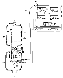
There is seen in FIG. 1 a low flow metering device 10. The flow range which
can be detected is typically from about 0.05 ml, that is about one droplet, up
to
about 6 liters, per hour.
A first chamber 12 has an inlet 14, and an outlet 16 in fluid communication
with a second chamber 17. Preferably the diameter of the outlet orifice 16 is
smaller
than the diameter of the inlet 14. Advantageously the diameter of the outlet
orificel6 is between about 3 and 6 mm, as such a size is suitable for forming
droplets 18 when a liquid 20 having a viscosity similar to water is passed
therethrough. However the outlet 16 is larger for handling more viscous fluids
such
as oil.
The first chamber 12 contains an element creating a laminar flow, which in
the present embodiment comprises a porous substance 24 supported by a
screening element 22. Suitably, the porous substance 24 is a fibrous mat.
Granular
particles 26, for example sand, may be used either alone or in combinations
with
the mat 24 as shown..
The outlet 16 of the first chamber 12 acts as a drop generator leading to a
lower second chamber 1.7. The outlet 16 is sized to release a series of
droplets 18,
each droplet 18 forming and breaking away under its own weight from liquid in
the
drop generator orifice 19.
CA 02360420 2001-07-13
WO 00/42394 PCT/ILOO/00027
7
An overflow conduit 21 extends between an upper area of the first chamber
12 and a lower area of the second chamber 17. One of the functions of the
conduit
21 is to equalize gas pressure between the two chambers 12, 17.
The conduit 21 also prevents flooding of the upper area in case of
unexpectedly fast inlet flows.
Electrodes 28 are positioned in the second chamber 17 in spaced-apart
relationship one above the other below the outlet orifice 16. This arrangement
allows operation of the device 10 even if installed slightly off the vertical
axis.
Electrodes 28 count and time the passage of each droplet 18 passing and
contacting electrodes 28. In the present embodiment a voltage is applied
between
the electrodes 28, and the resulting current is recorded. Current is
practically zero
when no droplet is present between electrodes 28, but does flow when a droplet
18
is in contact and bridges the electrodes 28.
If fluid conductivity is of interest the current value is recorded. If this is
not
required, the current is merely recorded as a pulse, which is counted
electronically.
Droplet counting is done by an information processing unit 30 electronically
connected to the electrodes 28 for receiving and recording information.
The information shown on the display 32 includes flow per unit time 34.
Additionally the display shows total flow 36, start time 38, and elapsed time
40.
In the present embodiment electrical conductivity of the fluid passing
between the electrodes is also shown 42. Electrical conductivity is an
indicator of
substances present in liquid 20 which, for example with urine, may be of
interest to
medical staff.
With reference to the rest of the figures, similar reference numerals have
been used to identify similar parts.
Referring now to FIG. 2a, there is seen a low-flow metering device 44
particularly useful for medical purposes.
The upper chamber 42, the lower chamber 46 and the electrodes 48 are part
of a self-contained disposable unit 50. Electrical connection means, such as a
socket 52 and plug 54, provide the connection to the information processing
unit 56.
Present hospital practice is to make increasingly wide use of disposable
items, as
the costs and risks associated with sterilization and re-use are high, and
sterilization
procedures are used mainly for high-cost metal items.
CA 02360420 2001-07-13
WO 00/42394 PCT/ILOO/00027
8
In the present embodiment 44 measurement accuracy is enhanced by the
addition of a drop size correction mechanism 58. Drop size varies as a non-
linear
function of time after separation of the previous drop. This relationship is
illustrated
in FIG. 2b, and this relationship is stored in an electronic look-up table
included in
the mechanism 58. The information processing unit 56 is in receipt of
information
as to the timing of drop release, and includes a correction mechanism based on
this
relationship which electronically adjusts the reported output flow 60 and
volume 62
after correction.
FIG. 3 illustrates a part of a low-flow metering device 64 similar to that
seen
in FIG. 1.
In the present embodiment the element creating a laminar flow is a molded
plastic labyrinth 66, which slows liquid flow while remaining resistant to
blockage by
solid particles below the size of the labyrinth passages.
Seen in FIG. 4 is a low-flow metering device 68 generally similar to that seen
in FIG. 1.
A reservoir bag 70 is positioned between a source of liquid 72 and the drop
generator 16,24,26. The bag 70 acts as a buffer between an intermittently fast
input
source 72 and the slow continuous discharge through output orifice 16. For
urine
monitoring, a bag up to 400 ml is usually suitable.
Referring now to FIG. 5, there is depicted a part of a low-flow metering
device 74, further comprising a calibrated collection bag 76 positioned to
receive
droplets 18 after their passage between electrodes 28. The collection bag 76
has
calibrations 78 and so provides a useful check on the information recorded
electronically by the display 32 seen in FIG. 1. In the present embodiment the
bag
76 has a 1.5 liter capacity, a transparent front 80, and a white opaque back
82 for
convenience of observing liquid 20 collected therein.
FIG. 6 shows a low-flow metering device 84 further comprising means for
communicating information from the processing unit 86 to a central monitor 88.
The
processing unit 86 is a microprocessor which includes a clock and an
arithmetic
logic unit, and may also include the drop size correction mechanism 58
described
with reference to FIGS. 2a and 2b. Electrodes 28 receive a voltage from a
supply
90. Current measurements from an electrode 28 are made and converted to
digital
form in the interface 92. Information is sent by cable 94, as shown in the
present
CA 02360420 2001-07-13
WO 00/42394 PCT/ILOO/00027
9
embodiment, or by infra-red signals. The central monitor 88 is of particular
value in
intensive care units, where a nurse is charged with the supervision of
multiple
patients. The central monitor 88 is connected to an alarm 96 which is
triggered by
data readings which require immediate action by the nursing staff.
Additionally an
alarm 97 connected to microprocessor 86 is provided at the site where flow
measurement is being carried out.
FIG. 7 shows an embodiment of the low-flow metering device 100 having
three flow paths.
A first path starts at the upper face of a filter element 108, which receives
an
ultra-low flow from the inlet 102. The filter element 108 has porous outer
walls 110,
the purpose of which will become apparent from the description of the second
flow
path. The third flow path refers to flows above design range.
The first flow path leads to the filter element lower face 112, into a filter
support cup
114. The flow path continues through a lower aperture 117 at the base of the
cup
114. The droplets following this path next run down the outer face of a
vertical tube
116, and from there enter the drop generator 104. The tube outer face is
advantageously provided with a groove 118 to facilitate descent of the
droplet.
The tube 116 serves three further purposes:
a) it equalizes air pressure between the upper 120 and lower 122 parts of the
chamber, which is helpful for obtaining consistent readings;
b) it supports the filter cup 114; and
c) it prevents flooding of the upper chamber 120 by serving as an overflow
tube in
case the device is subjected to fast flows for which it is not intended.
The second flow path leads from the upper face 106 to the filter element 108,
through a part of said element, and out through the filter element porous
walll10.
Discharge through the wall 110 occurs as the filter element 108 intentionally
is
made with a limited through-flow capacity. The second flow path continues into
the
upper chamber 120 and the into the drop generator 104
The third flow path refers to overload conditions. If input is so fast that
the
upper chamber 120 is almost full, the excess drains down inside tube 116. The
excess fluid is however directed over the electrodes 28, which sense unusually
long
liquid contact and report overflow and/or sound an alarm.
CA 02360420 2001-07-13
WO 00/42394 PCT/ILOO/00027
Outlet 140 can be connected to a collection bag 76, seen in FIG. 5. Should
the collection bag 76 be full and, due to an attendant not having replaced the
full
bag with an empty bag, a portion of the lower part of the chamber 122 will be
flooded. Electrodes 28 register the presence of a continuous supply of fluid
and
activate an alarm 96 seen in FIG. 6. However as air is trapped between the
fluid
entering the housing outlet 140 and the drop generator 104, flooding of the
drop
generator 104 is prevented. Consequently, after the collection bag 76 is
exchanged
for an empty bag, flow measurements will proceed immediately without
significant
errors.
The upper part 120 of the chamber is provided with an air vent 123.
Seen in detail in FIG. 8 is the drop generator 104 which comprises three
stacked components 122, 124, and 126.
An upper inlet funnel 127 receives fluid from either or both the flow paths
described with reference to FIG. 7, and directs the liquid to the intermediate
section
128 into the labyrinth inlet 124. The labyrinth 130 allows low flows to pass
normally,
but slows down flows which are too fast for direct conversion into discrete
drops.
The labyrinth outlet 132 is arranged to pass fluid to a lower section 126. A
drop-direction pin-like element 134 extends downwardly from the center of the
outlet orifice 136. A drop forming on the pin 134 falls when its size and
weight are
sufficient to overcome the surface tension of the fluid. The drop 138 falls to
contact
electrodes 28 and is then discharged through the chamber outlet 140.
Preferably the external wall 142 of the lower section 126 of the outlet
orifice
136 is made of a hydrophobic material such as fluorinated ethylene propylene.
This
prevents the drop 138 from backing up the external wall 142.
However the inner lining 144 of the lower section 126 of outlet orifice 136
and the internal parts of the labyrinth are preferably made of a hydrophilic
material,
for example polyethersulfone. Thereby fluid flow is eased, entrained air
bubbles are
released, and the pin 134 receives fluid in an orderly manner.
While not shown, multiple drop generators, according to the present
invention, can be arranged in parallel to monitor high flows.
While not shown in the figures, vent means can also be provided for
one or more of the chambers, if desired.
28-12-2000 . PC ~ , -,,.r;'_=% =p
T/JL00/00027 'DESCPAMD
CA 02360420 2001-07-13
11
It will be evident to those skilled in the art that the invention is not
limited
to the details of the foregoing illustrative embodiments and that the present
invention may be embodied in other specific forms without departing from the
scope of the claims. The present embodiments are therefore to be considered
in all respects as illustrative and not restrictive, the scope of the
invention being
indicated by the appended claims rather than by the foregoing description, and
all changes which come within the meaning and range of equivalency of the
claims are therefore intended to be embraced therein.
Pranled:05-0:1`200-1. AMENDED SHEET