Language selection

Search

Patent 2360427 Summary

Third-party information liability

Some of the information on this Web page has been provided by external sources. The Government of Canada is not responsible for the accuracy, reliability or currency of the information supplied by external sources. Users wishing to rely upon this information should consult directly with the source of the information. Content provided by external sources is not subject to official languages, privacy and accessibility requirements.

Claims and Abstract availability

Any discrepancies in the text and image of the Claims and Abstract are due to differing posting times. Text of the Claims and Abstract are posted:

  • At the time the application is open to public inspection;
  • At the time of issue of the patent (grant).
(12) Patent: (11) CA 2360427
(54) English Title: METHOD FOR MANUFACTURING A LAMP
(54) French Title: PROCEDE DE FABRICATION D'UNE LAMPE
Status: Expired and beyond the Period of Reversal
Bibliographic Data
(51) International Patent Classification (IPC):
  • H01J 09/00 (2006.01)
  • H01J 09/24 (2006.01)
  • H01J 09/40 (2006.01)
(72) Inventors :
  • FISCHER, GUDRUN (Germany)
  • HEIDER, JURGEN (Germany)
  • KOLBECK, ROLAND (Germany)
  • REICHARDT, JURGEN (Germany)
  • SCHULZKI, JOACHIM (Germany)
  • WEINHARDT, EROLF (Germany)
  • CONRAD, ANTHONY (Germany)
  • SCHAAF, JOHANNES (Germany)
(73) Owners :
  • PATENT-TREUHAND-GESELLSCHAFT FUER ELEKTRISCHE GLUEHLAMPEN MBH
(71) Applicants :
  • PATENT-TREUHAND-GESELLSCHAFT FUER ELEKTRISCHE GLUEHLAMPEN MBH (Germany)
(74) Agent: SMART & BIGGAR LP
(74) Associate agent:
(45) Issued: 2009-07-07
(86) PCT Filing Date: 2000-10-16
(87) Open to Public Inspection: 2001-05-25
Examination requested: 2005-06-15
Availability of licence: N/A
Dedicated to the Public: N/A
(25) Language of filing: English

Patent Cooperation Treaty (PCT): Yes
(86) PCT Filing Number: PCT/DE2000/003638
(87) International Publication Number: DE2000003638
(85) National Entry: 2001-07-09

(30) Application Priority Data:
Application No. Country/Territory Date
199 55 265.7 (Germany) 1999-11-17

Abstracts

English Abstract


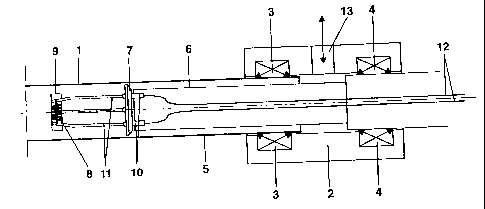
In the method for manufacturing a lamp, the
lamp vessel (1) is inserted gastightly with the open
end (5) into a pumping head (2) with a holder (6) which
bears a sealing plate (7) with an electrode system and
connecting pins (10). The sealing plate (7) has here an
external contour which is a little smaller than the
internal contour of the open end (5) of the lamp vessel
(1), so that the lamp vessel (1) can be pumped and
filled with gases via the pumping head (2). The edge of
the sealing plate (7) and the lamp vessel (1) are
subsequently heated so that the lamp vessel (1) buckles
in at the level of the sealing plate (7) and connects
gastightly to the edge of the sealing plate (7). The
protruding end (5) of the lamp vessel (1) is then cut
off.


French Abstract

La présente invention concerne un procédé de fabrication d'une lampe. Selon ce procédé, le tube de lampe (1) présentant l'extrémité ouverte (5) est monté étanche aux gaz, dans une tête de pompe (2), avec un support (6) qui porte une plaque de fermeture (7) pourvue d'un système d'électrodes et de pointes de raccordement (10). La plaque de fermeture (7) présente un contour extérieur qui est un peu plus petit que le contour intérieur de l'extrémité ouverte (5) du tube de lampe (1), de façon que le tube de lampe (1) peut être pompé par l'intermédiaire de la tête de pompe (2) et être rempli de gaz. Le bord de la plaque de fermeture (7) et le tube de lampe (1) sont alors chauffés, de façon que le tube de lampe (1) vienne à la hauteur de la plaque de fermeture (7) et se connecte, de façon étanche aux gaz, au bord de la plaque de fermeture (7). Ensuite, l'extrémité (5) du tube de lampe (1) qui fait saillie est séparée.

Claims

Note: Claims are shown in the official language in which they were submitted.


-7-
CLAIMS:
1. A method for manufacturing a lamp with a lamp
vessel which has at least one open, cylindrically formed end
into which an electrode system is introduced and which is
subsequently sealed gastightly, the method comprising:
inserting the lamp vessel gastightly with the at
least one open end into a pumping head, the pumping head
bearing, on a holder which can be displaced along the axis
of the lamp vessel, a sealing plate with the electrode
system and connecting pins in such a way that when the lamp
vessel is inserted into the pumping head the sealing plate
comes to bear perpendicularly with respect to the axis of
the cylindrical end of the lamp vessel, and the sealing
plate has an external contour which corresponds to the
internal contour of the cylindrical end of the lamp vessel
and is of such a magnitude that a distance between the
internal wall of the cylindrical end of the lamp vessel and
the edge of the sealing plate is defined;
pumping, rinsing, and filling the lamp vessel with
gases and possibly further filling substances to the desired
amount via the cylindrical end and the pumping head;
then heating the edge of the sealing plate and the
lamp vessel at the level of the sealing plate from the
outside using a power source so that the end of the lamp
vessel buckles in at the level of the sealing plate and
connects gastightly to the edge of the sealing plate; and
finally cutting off the open end of the lamp
vessel which protrudes beyond the sealing plate.

-8-
2. The method as claimed in claim 1, wherein the
cylindrical end of the lamp vessel has a circular internal
contour, and the sealing plate has a circular edge.
3. The method as claimed in claim 1, further
comprising rotating the power source about the lamp vessel
and the sealing plate during the heating procedure.
4. The method as claimed in claim 1, further
comprising rotating the lamp vessel and the sealing plate on
the power source during the heating procedure.
5. The method as claimed in claim 3 or 4, wherein the
power source is a gas burner.
6. The method as claimed in claim 1, wherein the lamp
to be manufactured is a fluorescent lamp with a tubular lamp
vessel, and to manufacture the lamp a glass tube which is
open at both ends and has a continuously circular internal
cross section is used, and the method further comprises
inserting the two ends of said glass tube simultaneously or
successively into a pumping head with a circular sealing
plate which is attached to a mount and has an electrode
system and connecting pins.
7. The method as claimed in claim 1, wherein the lamp
to be manufactured is an incandescent lamp with a light
bulb-shaped glass vessel and to manufacture it a light bulb-
shaped glass vessel is used which has an open end with
circular internal cross section, the method further
comprising inserting the open end into the pumping head with
a circular sealing plate which is attached to a holder.
8. The method as claimed in claim 1, wherein the
electrode system is composed of a single coil filament which

-9-
are mounted on the side of the sealing plate facing away
from the open end of the lamp vessel.
9. The method as claimed in claim 1, further
comprising mounting the connecting pins on the side of the
sealing plate facing the open end of the lamp vessel and are
electrically connecting the connecting pins to the single
coil filament via current feeder lines.
10. The method as claimed in claim 1, wherein the
sealing plate is composed of insulating glass.
11. The method as claimed in claim 9, wherein the
sealing plate is composed of metal, and the method further
comprises surrounding at least one of the current feeder
lines by insulating material in the region where it passes
through the sealing plate.
12. The method as claimed in claim 1, wherein the
sealing plate is composed of a glass stem at whose edge a
metal ring is mounted.
13. The method as claimed in claim 11, wherein the
insulating material is composed of glass solder.
14. The method as claimed in claim 8, wherein the
single coil filament bears an emitter, and the method
further comprises electrically connecting current feeder
lines for forming the emitter to a power source.
15. An electric lamp manufactured according to the
method as claimed in any one of claims 1 to 14.

Description

Note: Descriptions are shown in the official language in which they were submitted.


CA 02360427 2001-07-09
- 1 -
Patent-Treuhaiad-Gesellschaf t
fiir elektrische Gliihlampen mbH., Munich
Method for manufacturing a lamp
Technical Field
The invention is based on a method for
manufacturing a lamp according to the preamble of claim
1. This is a method for manufacturing a lamp. with a
lamp vessel.which has at least one open, cylindrically
formed end into which an'electrode system is introduced
and which is subsequently sealed gastightly.
Prior Art
In methods previously used for manufacturing a
lamp, whether incandescent or tubular fluorescent
Aamps;, the 'electrode* systems are- introduced into the
lamp vessels by means of a flare mount-and sealed in-
gastightly. Theelectrode system can be squeezed into
the open end or ends only with very small tube
diameters.
The flare mounting method requires in the stem
an additional pumping tube via which the lamps are
pumped, rinsed and filled with the necessary
substances. Because this pumping tube has to be sealed
gastightly after the filling procedure, this results in
an additional manufacturing step.
In addition, in a flare mount, a metal or
plastic base addition is required which is attached to
the flare mount by means of adhesive cement.

CA 02360427 2008-04-28
63312-94
- 2 -
The flare mount and the attachment of the base require
a complex machinery.
Description of the invention
An object of some embodiments of the
present invention is to make available a method for
manufacturing a lamp, in which it is possible to
dispense with a pumping tube and a subsequent attach-
ment to a base, and the machinery for manufacturing the
lamp is thus si.mplifi,Pd. -
In the method according to some embodiments of the
invention, the lamp vessel is inserted gastightly with the
at least
._ _._. _,-. .. _.. ..
one open cylindri~r1 -e_~ in~~ a ptimp
inq head, the
pun2ping head bearing, oti a holder, a sealing plate with
th-e electrode system and the connectin.g pins in such a
way that when the lamp vessel is inserted into-: the
pumping head the -sealing . plate comes to bear
-20 perpendicularly with respect to the axis of the
cylindrical end of the lamp vessel_ The holder can be
placed along the axis of the lamp vessel. The sealing
plate has here an external contour which is a little
smaller than the internal contour of the open end of
25. the lamp vessel. This makes it possible to pump' the
3.amp veasel, rinse it and _ fill it with. gases and
possibly further, filling substances to the desired
amount via the pumping head. The edge of the sealing
plate and the lamp vessel are then =heated at the level.
30 of the sealing plate from the -o.utside using a power
source so that-the end of the lamp vessel buckles in at
the level of- the sealing plate and connects gastightly
to the edge of the sealing plate. Finally,

CA 02360427 2001-07-09
- 3 -
the open end of the lamp vessel which protrudes beyond
the sealing plate is cut off.
The most simple form of the method is when- the
cylindrical end of the lamp vessel has a circular
=internal contour, and the sealing plate has a circular
edge.
It is 'advantageous for a vacuum tight sealing
of the lamp vessel that the power source rotates about
the lamp vessel and the sealing plate during the
heating procedure. However, with certain vessels it may
also be.advantageous if the lamp vessel and'the.sealing
plate rotate on the power source during the heating
procedure. A gas burner is preferably used here as the
power source.
In the event that the lamp to be manufactured
is a fluorescent lamp with a tubular lamp vessel with a
continuously circular cross section, and to manufacture
the lamp a glass tube which is open at both ends is
used, the two ends of said glass tube are inserted
-simultaneously or successively into the. pumping head.
with 'a circular sealing. pla.te which :is 'attached to a
mount and has the electrode system and the connecting
pins.
In the case of an =incandescent lamp with a
light bulb-shaped lamp vessel, in which case to
manufacture it a light bulb-shaped glass vessel is used
which has a circular-cylindrical open end, the
circular-cylindrical open end is inserted into the
pumping head with a circular sealing plate which is
3,0, attached to a . mount and has the electrode system and
the connecting pins.
The electrode system is advantageously composed
of a mount and a single coil filament which is attached
to it and which is mounted on the side of the sealing
plate facing away from the open end of the lamp vessel.
On the side of the sealing plate facing the open end of
the lamp vessel, electric

CA 02360427 2008-04-28
63312-94
- 4 -
connecting pins are mounted and electrically connected.to
the single coil filament via current feeder lines.
The sealing plate is advantageously composed of
insulating glass. It can however also be composed of metal,
in which case the current feeder lines are surrounded by
insulating material, for example glass solder, in the region
where they pass through the sealing plate. However, the
sealing plate can also be composed of a glass stem at whose
edge a metal ring is mounted.
If the single coil filament bears an emitter, the
current feeder lines for forming the emitter are
advantageously electrically connected to a power source.
The invention also relates to a lamp manufactured
according to the present method.
In accordance with one aspect of the invention,
there is provided a method for manufacturing a lamp with a
lamp vessel which has at least one open, cylindrically
formed end into which an electrode system is introduced and
which is subsequently sealed gastightly, the method
comprising: inserting the lamp vessel gastightly with the at
least one open end into a pumping head , the pumping head
bearing, on a holder which can be displaced along the axis
of the lamp vessel, a sealing plate with the electrode
system and connecting pins in such a way that when the lamp
vessel is inserted into the pumping head the sealing plate
comes to bear perpendicularly with respect to the axis of
the cylindrical end of the lamp vessel, and the sealing
plate has an external contour which corresponds to the
internal contour of the cylindrical end of the lamp vessel
and is of such a magnitude that a distance between the
internal wall of the cylindrical end of the lamp vessel and

CA 02360427 2008-04-28
63312-94
- 4a -
the edge of the sealing plate is defined; pumping, rinsing,
and filling the lamp vessel with gases and possibly further
filling substances to the desired amount via the cylindrical
end and the pumping head; then heating the edge of the
sealing plate and the lamp vessel at the level of the
sealing plate from the outside using a power source so that
the end of the lamp vessel buckles in at the level of the
sealing plate and connects gastightly to the edge of the
sealing plate; and finally cutting off the open end of the
lamp vessel which protrudes beyond the sealing plate.
Description of the drawings
The method according to the invention will be
explained in more detail below with reference to the
following figures, in which:
Figure 1 shows the method setup at the start of
the manufacturing method according to the invention for
manufacturing a tubular low pressure discharge lamp,
Figure 2 shows the method setup during the heating
of the sealing plate and lamp vessel,
Figure 3 shows the method setup after
disconnection of the protruding end of the lamp vessel,
Figure la shows the method setup at the start of
the manufacturing method according to the invention for
manufacturing a light bulb-shaped incandescent lamp.

CA 02360427 2001-07-09
- 5 -
Figure 1 shows the method setup at the start of
the manufacturing method according to the invention for
manufacturing a tubular low pressure discharge lamp.
The tubular lamp vessel 1. with circular
internal cross section is inserted here by its two ends
into one pumping head 2 in each case, the two seals, 3,
4 providing a vacuum tight seal from the surroundings.
In the present figures 1 to 3, just. one end 5 which is
inserted into a pumping head 2 is shown for the sake of
simplicity.
The pumping head 2 also bears, on a holder 6, a
sealing plate 7-made of glass, to which an electrode
system composed of a single coil filament 8 and an
integration cap 9 is attached on the side facing away
from the pumping head 2, and connecting pins 10, which
are connected to the single coil filament 8 via.current
feeder lines 11, are attached on the side facing the
pumping head 2. In addition, the connecting pins 10 for
forming a getter material are placed in electrica2
contact via cables 12.
The tubular.lamp vessel 1 can, then. be* pumped,
rinsed and filled with the required filling materials
via an opening 13 on the pumping head 2, which is
indicated by the double arrow.
Figure 2 shows the following method step of the
method acCording to the invention. The method setup is
essentially the same here as in the method setup
indicated in figure 1. However, an energy source in the
form of a gas burner 14 is additionally arranged in the
position of- the sealing plate 7. By rotating the ,lamp
vessel -l.and.the sealing plate 7_using the pumping head
2, the lamp vessel 1 at this point and the edge of the
sealing plate 7 are heated until the lamp vessel 1
buckles in at this point and connects gastightly to the
edge of the sealing plate 7.

CA 02360427 2001-07-09
The further method step whose setup is
illustrated in figure 3 shows the end 14 which is cut
off from the gastightly sealed lamp vessel 1. After the
pumping head 2 is flooded with atmospheric air via the
opening 13, on the basis of figure 2, the end 14 can be
pulled off the sealed-in lamp 15 and cut off by
displacing the pumping head 2, and the disconnection
point on the lamp 15 is molten. After the holder 6 is
then pulled. off from the connecting pins 10 and the
pumping head 2 is pulled off, the finished lamp 15 can
be removed, and after the release of the seal 3, the
end 14 can be removed.
Instead of tubular low pressure discharge
lamps, the method according to the invention can also
be applied in the lamps with a light bulb-shaped lamp
vessel such as an incandescent lamp.
Figure la shows the method setup for
manufacturing an incandescent lamp at the start of the
method, the setup corresponding very largely to the
20, method' setup shown in figure.1 for tubular low' pressure
discharge lairips. For this reason; the same parts of the
setup are designated by the same numbers as in' figure
1. Instead of the tubular lamp vessel, a light bulb-
shaped lamp vessel 16 with a circular-cylindrical open
end 17 is. inserted into the pumping head 2 here. The
sealing plate 18 bears here, on the side facing away
from the pumping head 2, a single coil filament 19
which is connected to the connecting pins 21 via
current feeder lines 20.
The sequence of the rest of the method for..
manufacturing an incandescent lamp corresponds in 'its
basic method steps to the method for manufacturing a
tubular low pressure discharge lamp. For this reason,
the further method steps have not been presented.

Representative Drawing
A single figure which represents the drawing illustrating the invention.
Administrative Status

2024-08-01:As part of the Next Generation Patents (NGP) transition, the Canadian Patents Database (CPD) now contains a more detailed Event History, which replicates the Event Log of our new back-office solution.

Please note that "Inactive:" events refers to events no longer in use in our new back-office solution.

For a clearer understanding of the status of the application/patent presented on this page, the site Disclaimer , as well as the definitions for Patent , Event History , Maintenance Fee  and Payment History  should be consulted.

Event History

Description Date
Time Limit for Reversal Expired 2015-10-16
Letter Sent 2014-10-16
Grant by Issuance 2009-07-07
Inactive: Cover page published 2009-07-06
Inactive: Final fee received 2009-04-22
Pre-grant 2009-04-22
Notice of Allowance is Issued 2009-03-02
Letter Sent 2009-03-02
Notice of Allowance is Issued 2009-03-02
Inactive: Approved for allowance (AFA) 2008-10-01
Amendment Received - Voluntary Amendment 2008-04-28
Inactive: S.29 Rules - Examiner requisition 2007-10-26
Inactive: S.30(2) Rules - Examiner requisition 2007-10-26
Inactive: IPC from MCD 2006-03-12
Letter Sent 2005-06-27
Request for Examination Received 2005-06-15
Request for Examination Requirements Determined Compliant 2005-06-15
All Requirements for Examination Determined Compliant 2005-06-15
Inactive: Cover page published 2001-12-07
Inactive: Notice - National entry - No RFE 2001-11-28
Inactive: First IPC assigned 2001-11-25
Application Received - PCT 2001-11-10
Inactive: Single transfer 2001-09-27
Application Published (Open to Public Inspection) 2001-05-25

Abandonment History

There is no abandonment history.

Maintenance Fee

The last payment was received on 2008-09-18

Note : If the full payment has not been received on or before the date indicated, a further fee may be required which may be one of the following

  • the reinstatement fee;
  • the late payment fee; or
  • additional fee to reverse deemed expiry.

Patent fees are adjusted on the 1st of January every year. The amounts above are the current amounts if received by December 31 of the current year.
Please refer to the CIPO Patent Fees web page to see all current fee amounts.

Owners on Record

Note: Records showing the ownership history in alphabetical order.

Current Owners on Record
PATENT-TREUHAND-GESELLSCHAFT FUER ELEKTRISCHE GLUEHLAMPEN MBH
Past Owners on Record
ANTHONY CONRAD
EROLF WEINHARDT
GUDRUN FISCHER
JOACHIM SCHULZKI
JOHANNES SCHAAF
JURGEN HEIDER
JURGEN REICHARDT
ROLAND KOLBECK
Past Owners that do not appear in the "Owners on Record" listing will appear in other documentation within the application.
Documents

To view selected files, please enter reCAPTCHA code :


To view images, click a link in the Document Description column. To download the documents, select one or more checkboxes in the first column and then click the "Download Selected in PDF format (Zip Archive)" or the "Download Selected as Single PDF" button.

List of published and non-published patent-specific documents on the CPD .

If you have any difficulty accessing content, you can call the Client Service Centre at 1-866-997-1936 or send them an e-mail at CIPO Client Service Centre.


Document
Description 
Date
(yyyy-mm-dd) 
Number of pages   Size of Image (KB) 
Representative drawing 2001-07-08 1 8
Abstract 2001-07-08 1 24
Claims 2001-07-08 5 141
Drawings 2001-07-08 4 49
Description 2001-07-08 6 270
Description 2008-04-27 7 304
Claims 2008-04-27 3 117
Abstract 2009-02-28 1 24
Representative drawing 2009-06-08 1 8
Notice of National Entry 2001-11-27 1 195
Reminder of maintenance fee due 2002-06-17 1 114
Reminder - Request for Examination 2005-06-19 1 115
Acknowledgement of Request for Examination 2005-06-26 1 175
Commissioner's Notice - Application Found Allowable 2009-03-01 1 162
Maintenance Fee Notice 2014-11-26 1 170
PCT 2001-07-08 4 150
Correspondence 2009-04-21 1 39