Note: Descriptions are shown in the official language in which they were submitted.
CA 02360457 2001-11-29
ENGINE HEAD COVER STRUCTURE
FIELD OF THE INVENTION
The present invention relates to handheld type four-cycle engines, which
are mainly used as a power source for machines for portable operation such as
trimmers. More particularly, it relates to improvement of an engine head cover
structure in which a head cover is joined to the upper end of a cylinder head
so
as to define a valve operation chamber between the cylinder head and the head
cover, and in the head cover are provided an oil recovery chamber which
recovers by suction oil resided in the valve operation chamber, and a breather
chamber which removes blowby gas from the valve operation chamber.
DESCRIPTION OF THE PRIOR ART
Such an engine head cover structure is already known as disclosed in,
for example, Japanese Patent Application Laid-open No. 11-125107.
In the engine head cover structure disclosed in the above-mentioned
publication, the roof of the head cover is split into upper and lower walls so
as to
define an oil recovery chamber therebetween, and a breather chamber is
defined between a partition plate mounted on an inner wall of the head cover
and a surface of the roof of the head cover.
Such an arrangement in which the roof of the head cover is split in order
to provide an oil recovery chamber requires an oil-tight joint around the
whole
periphery of the split roof in order to prevent oil leakage from the oil
recovery
chamber to the outside of the head cover. It is therefore necessary to inspect
the joint for oil-tightness, which is a barrier to reducing the production
cost.
1
CA 02360457 2001-11-29
The present invention has been carried out in view of the above-
mentioned circumstances, and it is an object of the present invention to
provide
an engine head cover structure that allows an oil recovery chamber and a
breather chamber to be formed without splitting the roof of the head cover and
makes inspecting the joint for oil tightness unnecessary thus contributing to
a
reduction in the production cost.
In accordance with a first characteristic of the present invention, in order
to achieve the above-mentioned object, there is proposed an engine head cover
structure having a head cover joined to the upper end of a cylinder head so as
to define a valve operation chamber therebetween, an oil recovery chamber to
which oil resided in the valve operation chamber is recovered by suction and a
breather chamber that removes blowby gas from the valve operation chamber,
wherein the breather chamber is defined between a partition plate mounted on
an inner wall of the head cover and a surface of the roof of the head cover,
and
the oil recovery chamber is formed integrally with the partition plate.
The above-mentioned valve operation chamber corresponds to a second
valve operation chamber 21 b of an embodiment of the present invention
described below.
In accordance with the above-mentioned first characteristic, the oil
recovery chamber and the breather chamber can be provided in the head cover
without splitting the roof of the head cover, and moreover, both the breather
chamber and the oil recovery chamber can be arranged within the head cover.
As a result, even if there is some oil leakage from the two chambers, the oil
merely returns to the valve operation chamber and does not cause any
problem. It is unnecessary to inspect the peripheries of the two chambers for
oil
tightness, and it is thus possible to reduce the production cost.
2
CA 02360457 2001-11-29
Furthermore, in accordance with a second characteristic of the present
invention, in addition to the above-mentioned first characteristic, there is
proposed an engine head cover structure wherein the oil recovery chamber is
defined between the surface of one side of the partition plate and a partition
body welded thereto.
In accordance with the second characteristic, the partition body can be
welded to the partition plate prior to mounting the partition plate on the
head
cover, and it is therefore possible to easily form the oil recovery chamber
using
the partition plate.
Furthermore, in accordance with a third characteristic of the present
invention, in addition to the above-mentioned second characteristic, there is
proposed an engine head cover structure wherein a first oil draw-up pipe that
opens in the vicinity of the base of the valve operation chamber while
communicating with the oil recovery chamber is formed integrally with one of
the partition plate and the partition body, and a second oil draw-up pipe that
opens in the vicinity of the roof of the head cover while communicating with
the
oil recovery chamber is formed integrally with the other one of the partition
plate
and the partition body.
In accordance with the above-mentioned third characteristic, the oil
resided in the valve operation chamber can be recovered to the oil recovery
chamber by means of the first and second oil draw-up pipes regardless of
whether the operational position of the engine is upright or upside down.
Moreover, since the first and second oil draw-up pipes are individually formed
with one or the other of the partition plate and the partition body, the first
and
second oil draw-up pipes can be formed easily.
The above-mentioned objects, other objects, characteristics and
advantages of the present invention will become apparent from an explanation
3
CA 02360457 2001-11-29
of a preferable embodiment which will be described in detail below by
reference
to the appended drawings.
BRIEF DESCRIPTION OF THE DRAWINGS
FIG. 1 is an oblique view showing one embodiment of the handheld type
four-cycle engine of the present invention in practical use.
FIG. 2 is a longitudinal side view of the above-mentioned four-cycle
engine.
FIG. 3 is a cross-sectional view at line 3-3 in FIG. 2.
FIG. 4 is a cross-sectional view at line 4-4. in FIG. 2.
FIG. 5 is a magnified view of an essential part of FIG. 2.
FIG. 6 is an exploded view of an essential part of FIG. 5.
FIG. 7 is a cross-sectional view at line 7-7 in FIG. 4.
FIG. 8 is a cross-sectional view at line 8-8 in FIG. 4.
FIG. 9 is a cross-sectional view at line 9-9 in FIG. 8.
FIG. 10 is a view from line 10-10 in FIG. 5 (bottom view of a head cover).
FIG. 11 is a cross-sectional view at line 11-11 in FIG. 5.
FIG. 12 is a diagram showing a lubrication route of the above-mentioned
engine.
Fig. 13 is a view corresponding to Fig. 4 in which the above-mentioned
engine is in an upside down state.
Fig. 14 is a view corresponding to Fig. 4 in which the above-mentioned
engine is in a laid-sideways state.
4
CA 02360457 2001-11-29
DESCRIPTION OF PREFERRED EMBODIMENT
An embodiment of the present invention is explained below by reference
to the appended drawings.
As shown in FIG. 1, a handheld type four-cycle engine E is attached as a
source of power to the drive section of, for example, a powered trimmer T.
Since the powered trimmer 'T is used in a manner in which a cutter C is
positioned so as to face in various directions according to the operational
conditions, the engine E is also tilted to a large extent or turned upside-
down as
a result and the operational position is changeable.
Firstly, the external structure of the handheld type four-cycle engine E is
explained by reference to FIGS. 2 and 3.
Attached to the front and back of an engine main body 1 of the above-
mentioned handheld type four-cycle engine E are a carburetor 2 and an exhaust
muffler 3 respectively, and an air cleaner 4 is attached to the inlet of the
carburetor 2. A fuel tank 5 made of a synthetic resin is mounted on the lower
face of the engine main body 1. Opposite ends of a crankshaft 13 project
outside the engine main body 1 and an oil tank 40 adjoining one side of the
engine main body 1, and a recoil type starter 42 that can be operatively
connected to a driven member 84 that is fixed to one end of the crankshaft 13
is
mounted on the outside face of the oil tank 40.
Fixed to the other end of the crankshaft 13 is a cooling fan 43 that also
serves as a flywheel. A plurality of fitting bosses 46 (one thereof is shown
in
FIG. 2) are formed on the outside face of the cooling fan 43, and a
centrifugal
shoe 47 is axially supported on each of the fitting bosses 46 in a swingable
manner. These centrifugal shoes 47, together with a clutch drum 48 fixed to a
drive shaft 50 which will be described below, form a centrifugal clutch 49 and
when the rotational rate of the crankshaft 13 exceeds a predetermined value
the
CA 02360457 2001-11-29
centrifugal shoes 47 are pressed onto the inner periphery of the clutch drum
48
due to the centrifugal force of the shoes 47, thereby transmitting the output
torque of the crankshaft 13 to the drive shaft 50. The cooling fan 43 has a
larger diameter than that of the centrifugal clutch 49.
An engine cover 51 covering the engine main body 1 and its attachments
except the fuel tank 5 is fixed at appropriate positions to the engine main
body
1, and a cooling air inlet 19 is provided between the engine cover 51 and the
fuel tank 5. Rotation of the cooling fan 43 therefore takes in outside air
through
the cooling air inlet 19 and supplies it for cooling each part of the engine
E.
Fixed to the engine cover 51 is a frustoconical bearing holder 58 that is
arranged coaxially with the crankshaft 13, and the bearing holder 58 supports,
via a bearing 59, the drive shaft 50 that rotates the cutter C.
Since the oil tank 40 and the starter 42 are arranged on one side of the
engine main body 1 and the cooling fan 43 and the centrifugal clutch 49 are
arranged on the other side thereof, the weight balance of the engine E in the
right and left directions is improved and the center of gravity of the engine
E can
be made closer to the central part of the engine main body 1, thereby
enhancing the handling performance of the engine E.
Furthermore, since the cooling fan 43 which has a larger diameter than
that of the centrifugal shoe 47 is fixed to the crankshaft 13 between the
engine
main body 1 and the centrifugal shoe 47, it is possible to minimize any
increase
in the dimensions of the engine E due to the cooling fan 43.
The structures of the engine main body 1 and the oil tank 40 are now
explained below by reference to FIGS. 2 to 6 and 10 and 11.
In FIGS. 2 to 5 the engine main body 1 includes a crankcase 6 having a
crank chamber 6a, a cylinder block 7 having one cylinder bore 7a, and a
cylinder head 8 having a combustion chamber 8a and intake and exhaust ports
6
CA 02360457 2001-11-29
9 and 10 that open into the combustion chamber 8a, and a large number of
cooling fins 38 are formed on the outer peripheries of the cylinder block 7
and
the cylinder head 8.
The crankshaft 13 housed in the crank chamber 6a is supported in the
left and right side walls of the crankcase 6 via ball bearings 14 and 14'. In
this
case, the left-hand ball bearing 14 is equipped with a seal, and an oil seal
17 is
provided so as to adjoin the outside of the right-hand ball bearing 14'. A
piston
15 fitted in the cylinder bore 7a is connected to the crankshaft 13 via a
connecting rod 16 in a conventional and general manner.
The oil tank 40 is provided so as to be integrally formed with the left-hand
wall of the crankcase 6 and is arranged so that the end of the crankshaft 13
on
the sealed ball bearing 14 side runs through the oil tank 40. An oil seal 39
through which the crankshaft 13 runs is fitted in the outside wall of the oil
tank
40.
A belt guide tube 86 having a flattened cross-section is pravided
integrally with the roof of the oil tank 40, the belt guide tube 86 running
vertically
through the roof of the oil tank 40 and having open upper and lower ends. The
lower end of the belt guide tube 86 extends toward the vicinity of the
crankshaft
13 within the oil tank 40, and the upper end is provided integrally with the
cylinder head 8 so as to share a dividing wall 85 with the cylinder head 8. A
continuous ring-shaped sealing bead 87 is formed around the periphery of the
upper end of the belt guide tube 86 and the cylinder head 8, and the dividing
wall 85 projects above the sealing bead 87.
As shown in FIGS. 6, 10 and 11, a ring-shaped sealing channel 88a
corresponding to the above-mentioned sealing bead 87 is formed in the lower
end face of a head cover 3fi, and a linear sealing channel 88b providing
communication between opposite sides of the ring-shaped channel 88a is
7
CA 02360457 2001-11-29
formed in the inner face of the cover 36. A ring-shaped packing 89a is fitted
in
the ring-shaped sealing channel 88a, and a linear packing 89b formed
integrally
with the ring-shaped packing 89a is fitted in the linear sealing channel 88b.
The
head cover 36 is joined to the cylinder head 8 by means of a bolt 37 so that
the
sealing bead 87 and the dividing wall 85 are pressed into contact with the
ring-
shaped packing 89a and the linear packing 89b respectively.
The belt guide tube 86 and one half of the head cover 36 define a first
valve operation chamber 21 a, the cylinder head 8 and the other half of the
head
cover 36 define a second valve operation chamber 21 b, and the two valve
operation chambers 21 a and 21 b are divided by the above-mentioned dividing
wall 85.
Referring again to FIGS. 2 to 5, the engine main body 1 and the oil tank
40 are divided into an upper block Ba and a lower block Bb on a plane that
includes the axis of the crankshaft 13 and is perpendicular to the axis of the
cylinder bore 7a. That is to say, the upper block Ba integrally includes the
upper half of the crankcase 6, the cylinder block 7, the cylinder head 8, the
upper half of the oil tank 40 and the belt guide tube 86. The lower block Bb
integrally includes the lower half of the crankcase 6 and the lower half of
the oil
tank 40. These upper and lower blocks Ba and Bb are cast individually, and
joined to each other by means of a plurality of bolts 12 (see FIG. 4) after
each
part has been machined.
Provided in the cylinder head 8 so as to be parallel to the axis of the
cylinder bore 7a are an intake valve 18i and an exhaust valve 18e for opening
and closing the intake port 9 and the exhaust port 10 respectively, and a
spark
plug 20 is screwed into the cylinder head 8 so that the electrodes thereof are
close to the central area of the combustion chamber 8a.
8
CA 02360457 2001-11-29
A valve operation mechanism 22 for opening and closing the above-
mentioned intake valve 18i and exhaust valve 18e is explained below by
reference to FIGS. 3 to 7.
The valve operation mechanism 22 includes a timing transmission 22a,
which runs from the interior of the oil tank 40 to the first valve operation
chamber 21 a, and a cam system 22b, which runs from the first valve operation
chamber 21 a to the second valve operation chamber 21 b.
The timing transmission 22a includes a drive pulley 23 fixed to the
crankshaft 13 within the oil tank 40, a driven pulley 24 rotatably supported
in the
upper part of the belt guide tube 86, and a timing belt 25 wrapped around
these
drive and driven pulleys 23 and 24. The end face of the driven pulley 24 on
the
dividing wall 85 side is joined integrally to a cam 26 forming part of the cam
system 22b. The drive and driven pulleys 23 and 24 are toothed, and the drive
pulley 23 drives the driven pulley 24 via the belt 25 with a reduction ratio
of 1/2.
A support wall 27 is formed integrally with the outside wall of the belt
guide tube 86, the support wall 27 rising inside the ring-shaped sealing bead
87
and being in contact with or in the vicinity of the inner face of the head
cover 36.
A through hole 28a and a bottomed hole 28b are provided in the support wall 27
and the dividing wall 85 respectively. Opposite ends of a support shaft 29 are
rotatably supported by the through hole 28a and the bottomed hole 28b, and the
above-mentioned driven pulley 24 and the cam 26 are rotatably supported on
the middle part of the support shaft 29. The support shaft 29 is inserted from
the through hole 28a into a shaft hole 35 of the driven pulley 24 and the cam
26
and the bottomed hole 28b before the head cover 36 is attached. By joining the
head cover 36 to the cylinder head 8 and the belt guide tube 86 subsequent to
the insertion, the inner face of the head cover 36 sits opposite the outer end
of
the support shaft 29 thereby preventing the shaft 29 from falling out.
9
CA 02360457 2001-11-29
Formed integrally with the dividing wall 85 on the second valve operation
chamber 21 b side are a pair of bearing bosses 30i and 30e projecting parallel
to
the support shaft 29. The cam system 22b includes the above-mentioned cam
26, an intake rocker shaft 31 i and an exhaust rocker shaft 31 a rotatably
supported in the above-mentioned bearing bosses 30i and 30e respectively, an
intake cam follower 32i and an exhaust cam follower 32e fixed to one end of
the
rocker shafts 31 i and 31 a respectively within the first valve operation
chamber
21 a, the extremity of each of the intake cam follower 32i and the exhaust cam
follower 32e being in sliding contact with the lower face of the cam 26, an
intake
rocker arm 33i and an exhaust rocker arm 33e fixed to the other end of the
intake and exhaust rocker shafts 31 i and 31 a respectively within the second
valve operation chamber 21 b, the extremity of each of the intake rocker arm
33i
and the exhaust rocker arm 33e being in contact with the upper end of the
intake valve 18i and exhaust valve 18e respectively, and an intake spring 34i
and an exhaust spring 34e mounted on the intake valve 18i and the exhaust
valve 18e respectively and forcing them in the closed direction.
When the crankshaft 13 rotates, the drive pulley 23 rotating together with
the crankshaft 13 rotates the driven pulley 24 and the cam 26 via the belt 25,
the cam 26 then rocks the intake and exhaust cam followers 32i and 32e with
appropriate timing, the rocking movements are transmitted to the intake and
exhaust rocker arms 33i and 33e via the corresponding rocker shafts 31 i and
31e, end the intake and exhaust rocker arms 33i and 33e so rocked can open
and close the intake and exhaust valves 18i and 18e with appropriate timing
while co-operatively working with the intake and exhaust springs 34i and 34e.
In the timing transmission 22a, since the driven pulley 24 and the cam 26
are rotatably supported by the support shaft 29 and the support shaft 29 is
also
rotatably supported in opposite side walls of the first valve operation
chamber
CA 02360457 2001-11-29
21 a, the support shaft 29 rotates due to frictional drag during rotation of
the
driven pulley 24 and the cam 26, the difference in rotational rate between the
support shaft 29 and the driven pulley 24 and the cam 26 decreases and
abrasion of the rotating and sliding areas can be suppressed, thus
contributing
to an improvement in the durability.
The lubrication system of the above-mentioned engine E is now
explained by reference to FIGS. 3 to 12.
As shown in FIGS. 4 and 5, the oil tank 40 stores a predetermined
amount of lubricating oil O poured in through an oil inlet 40a. Within the oil
tank
40, a pair of oil stingers 56a and 56b arranged on either side of the drive
pulley
23 in the axial direction are press-fitted, etc. onto the crankshaft 13. These
oil
stingers 56a and 56b extend in directions radially opposite to each other and
the
extremities thereof are bent so as to move away from each other in the axial
direction so that when the oil stingers 56a and 56b are rotated by the
crankshaft
13 at least one of the oil stingers 56a and 56b stirs and scatters the oil O
stored
within the oil tank 40, thereby generating an oil mist regardless of the
operational position of the engine E. In this case, the oil mist becomes
attached
to the part of the timing transmission 22a that extends within the oil tank 40
from
the first valve operation chamber 21 a, or the oil mist enters the first valve
operation chamber 21 a, and the timing transmission 22a can thus be lubricated
directly, which provides one lubrication system.
Another lubrication system includes, as shown in FIGS. 3 to 5 and 12, a
through hole 55 provided in the crankshaft 13 so as to provide communication
between the interior of the oil tank 40 and the crank chamber 6a, an oil feed
pipe 60 disposed outside the engine main body 1 so as to connect the lower
part of the crank chamber 6a to the lower part of the second valve operation
chamber 21 b, an oil recovery chamber 74 provided in the cylinder head 8 in
11
CA 02360457 2001-11-29
order to draw up oil liquefied and resided in the second valve operation
chamber 21 b, an oil return passage 78 formed between the cylinder head 8 and
the oil tank 40 so as to provide communication between the oil recovery
chamber 74 and the oil tank 40 via the first valve operation chamber 21 a, and
a
one-way valve 61 provided in the lower part of the crank chamber 6a and
allowing the flow of oil mist only in the direction from the crank chamber 6a
to
the oil feed pipe 60.
An open end 55a of the above-mentioned through hole 55 within the oil
tank 40 is positioned in the central part or the vicinity thereof within the
oil tank
40 so that the open end 55a is always above the liquid level of the oil O
within
the oil tank 40 regardless of the operational position of the engine E. The
drive
pulley 23 and one of the oil stingers 56a are fixed to the crankshaft 13 with
the
open end 55a therebetween so that it is not blocked.
The above-mentioned one-way valve 61 (see FIG. 3) is formed from a
reed valve in the illustrated embodiment; it closes when the pressure of the
crank chamber 6a becomes negative and opens when the pressure becomes
positive accompanying the reciprocating motion of the piston 15.
The lower end of the oil feed pipe 60 is connected by fitting it onto a
lower connection pipe 62a projectingly provided on the outside face of the
crankcase 6 (see FIG. 3) and the upper end of the oil feel pipe 60 is
connected
by fitting it onto an upper connection pipe 62b projectingly provided on the
outside face of the cylinder head 8 (see FIGS. 4 and 8). The interior of the
upper connection pipe 62b communicates on the one hand with the lower part
of the second valve operation chamber 21 b via a communicating passage 63
(see FIGS. 8 and 9) formed in the cylinder head 8 and having large dimensions,
and on the other hand with the oil return passage 78 via an orifice-like
bypass
64 (see FIG. 8).
12
CA 02360457 2001-11-29
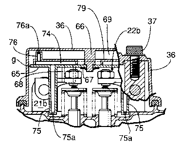
As shown in FIGS. 5, 10 and 11, a partition plate 65 defining a breather
chamber 69 in the upper part within the head cover 36 is fitted to the roof of
the
head cover 36 by means of a plurality of stays 66 and clips 67 fastened to the
stays 66, the stays 66 being projectingly provided on the roof. The breather
chamber 69 communicates on the one hand with the second valve operation
chamber 21 b via a communicating pipe 68 and a gap g between the inner face
of the head cover 36 and the partition plate 65, the communicating pipe 68,
which has large dimensions, being formed integrally with the partition plate
65
and projecting toward the second valve operation chamber 21 b, and on the
other hand with the interior of the above-mentioned air cleaner 4 via a
breather
pipe 70. In the breather chamber 69 a mixture of oil and blowby gas is
separated into gas and liquid, and a labyrinth wall 72 for promoting the gas-
liquid separation is projectingly provided on the inner face of the roof of
the
head cover 36.
The upper surface of the partition plate 65 is welded to a box-shaped
partition body 79, having one open face and being T-shaped in plan view, so as
to define the above-mentioned oil recovery chamber 74 therebetween, the oil
recovery chamber 74 therefore also being T-shaped.
Integral with the partition plate 65 are projectingly provided two draw-up
pipes 75, which respectively communicate with opposite ends of the lateral bar
of the T-shaped oil recovery chamber 74. The extremity of each of the draw-up
pipes 75 extends toward the vicinity of the base of the second valve operation
chamber 21 b, and an opening in the extremity of each of the draw-up pipes 75
forms an orifice 75a.
Integral with the upper wall of the partition body 79 are projectingly
provided three draw-up pipes 76, which communicate with three positions
corresponding to the extremities of the lateral and vertical bars of the T-
shape
13
CA 02360457 2001-11-29
of the oil recovery chamber 74. Each of the extremities of these draw-up pipes
76 extends toward the vicinity of the roof of the breather chamber 69, and an
opening in the extremity of each of the draw-up pipes 76 forms an orifice 76a.
Furthermore, in the upper wall of the partition body 79 is provided an
orifice 80, providing communication between an indentation 79a in the upper
face of the partition body 79 and the oil recovery chamber 74.
Moreover, integral with the partition plate 65 is projectingly provided one
pipe 81 communicating with a region corresponding to the extremity of the
vertical bar of the T-shape of the oil recovery chamber 74. The extremity of
the
pipe 81 is fitted into an inlet 78a of the above-mentioned oil return passage
78
via a grommet 82, the inlet 78a opening onto the base of the second valve
operation chamber 21 b. The oil recovery chamber 74 is thereby connected to
the oil return passage 78. The above-mentioned pipe 81 is placed close to an
inner side face of the second valve operation chamber 21 b, and an orifice 81
a
for drawing up oil is provided in the region close to the above-mentioned
inner
side face, the orifice 81 a providing communication between the second valve
operation chamber 21 b and the interior of the pipe 81.
Since the breather chamber 69 communicates with the interior of the air
cleaner 4 via the breather pipe 70, the pressure of the breather chamber 69 is
maintained at substantially atmospheric pressure even during operation of the
engine E, and the pressure of the second valve operation chamber 21 b
communicating with the breather chamber 69 via the communicating pipe 68,
which has a low flow resistance, is substantially the same as that of the
breather chamber 69.
Since the crank chamber 6a discharges only the positive pressure
component of the pressure pulsations caused by the ascending and descending
motion of the piston 15 into the oil feed pipe 60 through the one-way valve 61
14
CA 02360457 2001-11-29
during operation of the engine E, the pressure of the crank chamber 6a is
negative on average, and since the second valve operation chamber 21 b
receiving the above-mentioned positive pressure communicates with the
breather chamber 69 via the communicating pipe 68 having a small flow
resistance, the pressure of the second valve operation chamber 21 b is
substantially the same as that of the breather chamber 69. Since the negative
pressure of the crank chamber 6a is transmitted to the oil tank 40 via the
through hole 55 of the crankshaft 13 and further to the oil recovery chamber
74
via the oil return passage 78, the pressure of the oil recovery chamber 74 is
lower than those of the second valve operation chamber 21 b and the breather
chamber 69, and the pressures of the oil tank 40 and the first valve operation
chamber 21 a are lower than that of the oil recovery chamber 74.
As shown in FIG. 12, if the pressure of the crank chamber 6a is denoted
by Pc, the pressure of the oil tank 40 is denoted by Po, the pressure of the
first
valve operation chamber 21 a is denoted by Pva, the pressure of the second
valve operation chamber 21 b is denoted by Pvb, the pressure of the oil
recovery
chamber 74 is denoted by Ps, and the pressure of the breather chamber 69 is
denoted by Pb, the following relationship is therefore satisfied.
Pvb = Pb > Ps > Po = Pva > Pc
As a result, the pressure of the second valve operation chamber 21 b and
the breather chamber 69 is transferred to the oil recovery chamber 74 via the
draw-up pipes 75 and 76 and the orifice 80, further to the oil tank 40 via the
oil
return passage 78 and then to the crank chamber 6a.
During operation of the engine E, oil mist is generated by the oil stingers
56a and 56b stirring and scattering the lubricating oil O within the oil tank
40,
the oil stingers 56a and 56b being rotated by the crankshaft 13. As
CA 02360457 2001-11-29
hereinbefore described, the oil droplets so generated is splashed over the
part
of the timing transmission 22a exposed within the oil tank 40 from the belt
guide
tube 86, that is to say, the drive pulley 23 and part of the timing belt 25,
or the
oil droplets enter the first valve operation chamber 21 a, and the timing
transmission 22a is thus lubricated directly.
The oil mist generated in the oil tank 40 is drawn into the crank chamber
6a via the through hole 55 of the crankshaft 13 along the direction of the
above-
mentioned pressure flow, thereby lubricating the area around the crankshaft 13
and the piston 15. When the pressure of the crank chamber 6a becomes
positive due to the piston 15 descending, the one-way valve 61 opens and the
above-mentioned oil mist together with the blowby gas generated in the crank
chamber 6a ascend through the oil feed pipe 60 and the communicating
passage 63 and are supplied to the second valve operation chamber 21 b,
thereby lubricating each part of the cam system 22b within the chamber 21 b,
that is to say, the intake and exhaust rocker arms 33i and 33e ,etc.
In this case, a portion of the oil mist passing through the above-
mentioned communicating passage 63 is shunted to the oil return passage 78
via the orifice-like bypass 64. It is therefore possible to control the amount
of oil
mist supplied to the second valve operation chamber 21 b by setting the flow
resistance of the bypass 64 appropriately.
The oil mist and the blowby gas within the second valve operation
chamber 21 b are separated into gas and liquid by expansion and collision with
the labyrinth wall 72 while being transferred to the breather chamber 69
through
the communicating pipe 68 and the gap g around the partition plate 65, and the
blowby gas is taken into the engine E via the breather pipe 70 and the air
cleaner 4 in that order during the intake stroke of the engine E.
16
CA 02360457 2001-11-29
When the engine E is in an upright state, since the oil liquefied in the
breather chamber 69 resides in the indentation 79a in the upper face of the
partition body 79 or flows down the communicating pipe 68 or through the gap g
and is resided on the base of the second valve operation chamber 21 b, in that
case the oil is drawn up by means of the orifice 80 or the draw-up pipe 75
provided in those places into the oil recovery chamber 74. When the engine E
is in an upside down state, since the above-mentioned liquefied oil resides on
the roof of the head cover 36, in that case the oil is drawn up by means of
the
draw-up pipe 76 provided there into the oil recovery chamber 74.
The oil thus drawn up into the oil recovery chamber 74 returns from the
pipe 81 into the oil tank 40 via the oil return passage 78. In this case, when
the
oil return passage 78 communicates with the oil tank 40 via the first valve
operation chamber 21 a as in the illustrated embodiment, the oil discharged
from
the oil return passage 78 is splashed over the timing transmission 22a,
thereby
advantageously lubricating it.
Since the roof of the head cover 36 and the partition plate 65 attached to
the inner wall of the head cover 36 define the above-mentioned breather
chamber 69 therebetween and the upper face of the above-mentioned partition
plate 65 and the partition body 79 welded to the partition plate 65 define the
above-mentioned oil recovery chamber 74 therebetween, the oil recovery
chamber 74 and the breather chamber 69 can be provided in the head cover 36
without splitting the roof of the head cover 36. Moreover, since the breather
chamber 69 and the oil recovery chamber 74 are present within the head cover
36, even if some oil leaks from either of the chambers 69 and 74, the oil
simply
returns to the second valve operation chamber 21 b without causing any
problems, it is unnecessary to inspect the peripheries of the two chambers 69
and 74 for oil tightness and the production cost can thus be reduced.
17
CA 02360457 2001-11-29
Since the partition body 79 can be welded to the partition plate 65 before
attaching the partition plate 65 to the head cover 36, the oil recovery
chamber
74 can easily be formed using the partition plate 65.
Furthermore, since the oil draw-up pipes 75 and 76 are formed integrally
with the partition plate 65 and the partition body 79 respectively, the oil
draw-up
pipes 75 and 76 can easily be formed.
When the engine E is in an upside down state as shown in FIG. 13, the
oil O stored in the oil tank 40 moves toward the roof of the tank 40, that is
to
say, the first valve operation chamber 21 a side. Since the open end of the
first
valve operation chamber 21 a within the oil tank 40 is set so as to be at a
higher
level than the liquid level of the stored oil O by means of the belt guide
tube 86,
the stored oil O is prevented from entering the first valve operation chamber
21 a, thereby preventing excess oil from being supplied to the timing
transmission 22a, and it is also possible to maintain a predetermined amount
of
oil within the oil tank 40, thus allowing the oil stingers 56a and 56b to
continuously generate an oil mist.
When the engine E is laid sideways during its operation as shown in FIG.
14, the stored oil O moves toward the side face of the oil tank 40, and, in
this
case also, since the open end of the first valve operation chamber 21 a within
the oil tank 40 is set so as to be at a higher level than the liquid level of
the
stored oil O by means of the belt guide tube 86, the stored oil O is prevented
from entering the first valve operation chamber 21 a and it is possible to
prevent
excess oil from being supplied to the timing transmission 22a and also to
maintain a predetermined amount of oil within the oil tank 40, thus allowing
the
oil stingers 56a and 56b to continuously generate an oil mist.
The lubrication system for the valve operation mechanism 22 can thus be
divided into a system for lubricating part of the cam system 22b and the
timing
18
CA 02360457 2001-11-29
transmission 22a within the first valve operation chamber 21 a and the oil
tank
40 with the oil scattered within the oil tank 40, and a system for lubricating
the
remainder of the cam system 22b within the second valve operation chamber
21 b with the oil mist transferred to the second valve operation chamber 21 b.
The load put on each of the lubrication systems can thus be reduced and the
entire valve operation mechanism 22 can be lubricated thoroughly. Moreover,
each part of the engine E can be lubricated reliably by the use of oil
droplets
and oil mist regardless of the operational position of the engine E.
Since the oil mist generated within the oil tank 40 is returned by utilizing
the pressure pulsations within the crank chamber 6a and the one-way transfer
function of the one-way valve 61, it is unnecessary to employ a special oil
pump
for circulating the oil mist and the structure can be simplified.
Furthermore, not only the oil tank 40 but also the oil feed pipe 60
providing communication between the crank chamber 6a and the second valve
operation chamber 21 b are disposed outside the engine main body 1, which
does not prevent making the engine main body 1 thinner and more compact,
greatly contributing to reduction in the weight of the engine E. In
particular,
since the externally placed oil feed pipe 60 is little influenced by the heat
of the
engine main body 1 and easily releases its heat, cooling of the oil mist
passing
through the oil feed pipe 60 can be promoted.
Furthermore, since the oil tank 40 is placed on one side of the exterior of
the engine main body 1, the total height of the engine E can be greatly
reduced,
and since part of the timing transmission 22a is housed in the oil tank 40,
any
increase in the width of the engine E can be minimized, thus making the engine
E more compact.
The number of oil draw-up pipes 75 and 76 and orifices 80 and 81 a for
drawing up oil and the positions in which they are placed can be chosen
freely.
19
CA 02360457 2001-11-29
Furthermore, the partition body 79 can be welded to the lower face of the
partition plate 65, thereby forming the oil recovery chamber 74 below the
partition plate 65. In this case, the oil draw-up pipe 75 is formed integrally
with
the partition body 79 and the oil draw-up pipe 76 is formed integrally with
the
partition plate 65.
Moreover, instead of the one way valve 61, a rotary valve can be
provided, the rotary valve being operable in association with the crankshaft
13
and operating so as to open the oil feed pipe 60 when the piston 15 descends
and block the oil feed pipe 60 when the piston 15 ascends.
The present invention is not limited to the above-mentioned embodiment
and can be modified in a variety of ways without departing from the spirit and
scope of the invention.