Language selection

Search

Patent 2360737 Summary

Third-party information liability

Some of the information on this Web page has been provided by external sources. The Government of Canada is not responsible for the accuracy, reliability or currency of the information supplied by external sources. Users wishing to rely upon this information should consult directly with the source of the information. Content provided by external sources is not subject to official languages, privacy and accessibility requirements.

Claims and Abstract availability

Any discrepancies in the text and image of the Claims and Abstract are due to differing posting times. Text of the Claims and Abstract are posted:

  • At the time the application is open to public inspection;
  • At the time of issue of the patent (grant).
(12) Patent Application: (11) CA 2360737
(54) English Title: ELECTRICAL CONNECTOR
(54) French Title: CONNECTEUR ELECTRIQUE
Status: Deemed Abandoned and Beyond the Period of Reinstatement - Pending Response to Notice of Disregarded Communication
Bibliographic Data
(51) International Patent Classification (IPC):
  • H01R 13/58 (2006.01)
(72) Inventors :
  • LEENDERTSE, FRANCISCUS, HENDRICUS
  • DE WAARD, DANIEL
(73) Owners :
  • FOKKER ELMO B.V.
(71) Applicants :
  • FOKKER ELMO B.V.
(74) Agent: SMART & BIGGAR LP
(74) Associate agent:
(45) Issued:
(86) PCT Filing Date: 2000-11-23
(87) Open to Public Inspection: 2001-05-31
Availability of licence: N/A
Dedicated to the Public: N/A
(25) Language of filing: English

Patent Cooperation Treaty (PCT): Yes
(86) PCT Filing Number: PCT/NL2000/000857
(87) International Publication Number: WO 2001039334
(85) National Entry: 2001-07-23

(30) Application Priority Data:
Application No. Country/Territory Date
1013650 (Netherlands (Kingdom of the)) 1999-11-23

Abstracts

English Abstract


A connector comprises a housing having at least one contact element to which
an electrical conductor can be fixed, as well as a strain relief, connected to
the housing, for transmitting tensile forces between the electrical conductor
and the housing. The strain relief comprises a sleeve which consists of at
least one part, is able to engage on the electrical conductor and is connected
to the housing by means of an interlocking hook connection.


French Abstract

L'invention concerne un connecteur. Ce connecteur comprend un boîtier avec au moins un élément de contact auquel peut être fixé un conducteur électrique, ainsi qu'un réducteur de tension, relié au boîtier pour transmettre les efforts de traction entre le conducteur électrique et le boîtier. Le réducteur de tension comprend un manchon qui se compose au moins d'une partie qui peut se mettre en prise avec le conducteur électrique et est reliée au boîtier au moyen d'un raccordement par crochet .

Claims

Note: Claims are shown in the official language in which they were submitted.

4
Claims
1. Connector comprising a housing (1) having at least one contact element (8)
to which
an electrical conductor (18) can be fixed, as well as a strain relief (2),
connected to the
housing (1), for transmitting tensile forces between the electrical conductor
(18) and the
housing (1), characterised in that the strain relief (2) comprises a sleeve
(2) which consists
of at least one part, is able to engage on the electrical conductor (18) and
is connected to
the housing (1) by means of an interlocking hook connection (10, 13).
2. Connector according to Claim 1, wherein the interlocking hook connection
comprises
at least one hook element (10) on the housing (1) as well as at least one hook
element (13)
on the sleeve (2).
3. Connector according to Claim 2, wherein the housing (1) comprises a ring
(9)
constructed as an integral whole therewith and having an inward-facing hooked
edge (10)
and the sleeve (2) has an outward-facing hooked edge (13) that is hooked
behind the
inward-facing hooked edge (10) of the housing (1).
4. Connector according to Claim 2, wherein the ring (9) has a lip (11)
constructed as an
integral whole therewith, which lip (11) protrudes in the axial direction of
the housing (1)
and extends over a portion of the ring (9), in the peripheral direction
thereof.
5. Connector according to Claim 4, wherein the lip (11) has an inward-facing
ridge (12)
and the sleeve (2) has a corresponding recess (14) in which the ridge (12) can
be
accommodated.
6. Connector according to Claim 5, wherein the ridge (12) is offset in the
axial direction
of the housing (1) relative to the hooked edge (10) thereof.
7. Connector according to Claim 6, wherein the ridge (12) is further away from
the
housing (1) than is the hooked edge (10).
8. Connector according to Claim 5, 6 or 7, wherein the hooked edge (10) and
the ridge

5
(12) of the housing (1) are located opposite one another.
9. Connector according to Claim 5, 6, 7 or 8, wherein the recess (4) of the
sleeve (2) is
offset, in the axial direction of the housing (1), with respect to the hooked
edge (13)
thereof.
10. Connector according to Claim 9, wherein the hooked edge (13) and the
recess (14) in
the sleeve (2) are located opposite one another.
11. Connector according to one of the preceding claims, wherein the sleeve
consists of
one piece and is slit in the longitudinal direction.
12 Connector according to one of the preceding Claims 1-8, wherein the sleeve
(2)
consists of two identical sleeve halves (3, 4).
13. Connector according to Claim 11 or 12, wherein, on the outer surface of
the lip (11),
the ridge (12) together with the recess (14) in the sleeve (2) forms a
circular groove in
which a tensioning element (17) is located for clamping the sleeve (2) on the
electrical
conductor(s).
14. Connector according to one of the preceding claims, wherein the internal
passage in
the sleeve (2) is made such that it gradually narrows in the direction of the
housing (1).
15. Connector according to one of the preceding claims, wherein the housing
(1)
comprises an outer shell (5) and a plug (6) which is constructed as an
integral whole with
the outer shell (5) and incorporates the at least one contact element (8).
16. Connector according to one of the preceding claims, wherein the internal
passage in
the sleeve (2) is curved towards the side of the housing.

Description

Note: Descriptions are shown in the official language in which they were submitted.


CA 02360737 2001-07-23
WO 01/39334 PCT/NL00/00857
ELECTRICAL CONNECTOR
The invention relates to a connector comprising a housing having at least one
contact
element to which an electrical conductor can be fixed, as well as a strain
relief, connected
to the housing, for transmitting tensile forces between the electrical
conductor and the
housing.
A connector of this type is known. This known connector has a number of
sockets,
each of which is connected to an electrical conductor. The electrical
conductors together
form a bundle that is firmly connected to the housing by means of the strain
relief. By this
means, the electrical connection between each conductor and socket is
protected against
mechanical stresses.
The strain relief is constructed as a separate ring that is screwed onto the
back of the
housing and has a clamp for clamping the bundle. Said clamp has two halves,
which are
fixed to one another by means of screws.
This known connector has various disadvantages. The costs are fairly high, if
only
because of the relatively large number of components and the complex shape of
the strain
relief and the housing. Moreover, the electrical conductivity of the
connection between
strain relief and housing is less good, which is a disadvantage especially in
the case of
bundles that have been protected against electromagnetic pulses by means of a
metal
screen.
The aim of the invention is to provide a connector of the type described above
that
does not have these disadvantages. Said aim is achieved in that the strain
relief comprises a
sleeve which consists of at least one part, is able to engage on the
electrical conductor and
is connected to the housing by means of an interlocking hook connection.
The strain relief constructed as a sleeve can be fixed to the housing without
supplementary components such as screws or brackets, which enables efficient
and
inexpensive connection between the connector and the cable. The interlocking
hook
connection preferably comprises at least one hook element on the housing or
the sleeve as
well as at least one hook element on the other of these two components, i.e.
said sleeve or
said housing.
In order as far as possible to restrict the number of separate components in
the
connector, the housing can comprise a ring constructed as an integral whole
therewith and
having an inward-facing hooked edge and the sleeve can have an outward-facing
hooked

CA 02360737 2001-07-23
WO 01/39334 PCT/NL00/00857
2
edge that is hooked behind the inward-facing hooked edge of the housing.
Furthermore, the ring can have a lip constructed as an integral whole
therewith,
which lip protrudes in the axial direction of the housing and extends over a
portion of the
ring, in the peripheral direction thereof. Said ring provides supplementary
support for the
sleeve, as a result of which the strain relief is further stabilised. The lip
can have an inward-
facing ridge and the sleeve can have a corresponding recess in which the ridge
can be
accommodated.
Very reliable fixing of the sleeve to the housing is obtained if the ridge is
offset in the
axial direction of the housing relative to the hooked edge.
The hooked edge and the ridge of the housing are located opposite one another,
whilst the hooked edge and the recess in the sleeve are correspondingly
located opposite
one another. The sleeve is thus locked in a stable manner between the hooked
edge and the
ridge of the housing.
The sleeve can be constructed in various ways. According to a first
possibility, the
sleeve can be in one piece and slit in the longitudinal direction. When
fitting the sleeve
between the hooked edge and the ridge of the housing, the sleeve can initially
be
compressed. The sleeve is then able to spring back into shape, such that it
becomes rigidly
held behind said hooked edge and ridge.
According to a second possibility the sleeve consists of two identical sleeve
halves.
These sleeve halves can be held together in contact with the electrical
conductors) by
means of a tensioning element.
Such a tensioning element can also be used with the split sleeve consisting of
one
piece.
The internal passage in the sleeve can be made such that it gradually narrows,
in
order to obtain uniform clamping of the electrical conductor.
The housing can comprise an outer shell and a plug which is constructed as an
integral whole with the outer shell and incorporates the at least one contact
element.
The invention will be explained in more detail below with reference to an
illustrative
embodiment of the connector shown in the figures.
Figure 1 shows a longitudinal section through the housing of the connector
according
to the invention.
Figure 2 shows a longitudinal section through a sleeve.
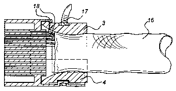
Figure 3 shows a longitudinal section through the assembly of housing and
sleeve.

CA 02360737 2001-07-23
WO 01/39334 PCT/NL00/00857
3
Figure 4 shows a rear view of the housing according to Figure 1.
Figure S shows a front view of a sleeve consisting of two halves.
Figure 6 shows a front view of a sleeve consisting of one piece.
The connector according to the invention comprises the housing 1 shown in
Figure 1
and the sleeve 2 shown in Figure 2, which sleeve 2 comprises two sleeve halves
3, 4. The
housing 1 consists of one piece and comprises an outer shell 5 as well as a
plug 6 provided
with passages 7 in each of which one electrical contact element 8 is located.
The plug is readily accessible so that the electrical conductors 18 can be
fixed to the
contact elements 8 quickly and easily.
The housing comprises an integral ring 9, which has a hooked edge 10. A lip
11, that
has an inward-facing ridge 12, protrudes with respect to the ring 9.
Each of the sleeve halves 3, 4 also has a hooked edge 13 and a recess 14. The
hooked
edge 13 and recess 14 are axially offset with respect to one another,
corresponding to the
axial distance between the hooked edge 10 of the housing 1 and the ridge 12 on
the lip 11
thereof.
As shown in Figure 3, the hooked edge 13 of the one sleeve half 3 is hooked
behind
the hooked edge 10 of the housing 1. The ridge 12 on the lip 11 of the housing
1 is
accommodated in the recess 14 of the other sleeve half 4.
The sleeve halves 3, 4 have a narrowing internal passage, defined by the
curved
internal walls 15. As shown in Figure 3, the cable, indicated in its entirety
by 16, can be
firmly clamped by this means. To this end the sleeve halves 3, 4 are forced
towards one
another by means of the pretensioning element 17.
The sleeve halves 3, 4 thus act as strain relief, by means of which any
tensile forces
in the cable 16 are transmitted directly thereto via the hooked edge 10 and
the ridge 12 of
the housing 1, without any strain being exerted on the electrical conductors
18.
Although the sleeve 2 according to Figure 5, consisting of two separate halves
3, 4,
has been discussed above, the one-piece sleeve according to Figure 6 can also
be used. Said
one-piece sleeve has a longitudinal slit 17 and consequently is able to be
elastically
compressed and then spring back, such that the hooked edge 13 can engage
behind the
hooked edge 10.

Representative Drawing
A single figure which represents the drawing illustrating the invention.
Administrative Status

2024-08-01:As part of the Next Generation Patents (NGP) transition, the Canadian Patents Database (CPD) now contains a more detailed Event History, which replicates the Event Log of our new back-office solution.

Please note that "Inactive:" events refers to events no longer in use in our new back-office solution.

For a clearer understanding of the status of the application/patent presented on this page, the site Disclaimer , as well as the definitions for Patent , Event History , Maintenance Fee  and Payment History  should be consulted.

Event History

Description Date
Time Limit for Reversal Expired 2004-11-23
Application Not Reinstated by Deadline 2004-11-23
Deemed Abandoned - Failure to Respond to Maintenance Fee Notice 2003-11-24
Letter Sent 2002-04-24
Inactive: Single transfer 2002-03-04
Inactive: Courtesy letter - Evidence 2001-12-11
Inactive: Cover page published 2001-12-11
Inactive: Notice - National entry - No RFE 2001-12-10
Inactive: First IPC assigned 2001-12-02
Application Received - PCT 2001-11-15
Application Published (Open to Public Inspection) 2001-05-31

Abandonment History

Abandonment Date Reason Reinstatement Date
2003-11-24

Maintenance Fee

The last payment was received on 2002-10-29

Note : If the full payment has not been received on or before the date indicated, a further fee may be required which may be one of the following

  • the reinstatement fee;
  • the late payment fee; or
  • additional fee to reverse deemed expiry.

Please refer to the CIPO Patent Fees web page to see all current fee amounts.

Fee History

Fee Type Anniversary Year Due Date Paid Date
Basic national fee - standard 2001-07-23
Registration of a document 2002-03-04
MF (application, 2nd anniv.) - standard 02 2002-11-25 2002-10-29
Owners on Record

Note: Records showing the ownership history in alphabetical order.

Current Owners on Record
FOKKER ELMO B.V.
Past Owners on Record
DANIEL DE WAARD
FRANCISCUS, HENDRICUS LEENDERTSE
Past Owners that do not appear in the "Owners on Record" listing will appear in other documentation within the application.
Documents

To view selected files, please enter reCAPTCHA code :


To view images, click a link in the Document Description column. To download the documents, select one or more checkboxes in the first column and then click the "Download Selected in PDF format (Zip Archive)" or the "Download Selected as Single PDF" button.

List of published and non-published patent-specific documents on the CPD .

If you have any difficulty accessing content, you can call the Client Service Centre at 1-866-997-1936 or send them an e-mail at CIPO Client Service Centre.


Document
Description 
Date
(yyyy-mm-dd) 
Number of pages   Size of Image (KB) 
Representative drawing 2001-07-23 1 9
Claims 2001-07-23 2 77
Abstract 2001-07-23 1 61
Drawings 2001-07-23 2 31
Description 2001-07-23 3 159
Cover Page 2001-12-11 1 36
Notice of National Entry 2001-12-10 1 195
Courtesy - Certificate of registration (related document(s)) 2002-04-24 1 114
Reminder of maintenance fee due 2002-07-24 1 114
Courtesy - Abandonment Letter (Maintenance Fee) 2004-01-19 1 176
PCT 2001-07-23 3 82
Correspondence 2001-12-11 1 24
Fees 2002-10-29 1 36